SMA to SMA Cable: Loss, Bend & Ordering Guide
Oct 14,2025
Introduction
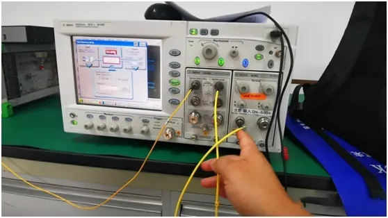
When you’re wiring an RF setup—say a Wi-Fi module, a test bench, or a 5 GHz access point—the short jumper that quietly decides whether your signal stays clean or falls apart is the SMA to SMA cable.
It’s one of those small details that can turn a “good enough” project into a stable, repeatable system.
Every RF engineer learns quickly that the quality of an RF coaxial cable shapes everything downstream.
A small mismatch or bend can cause reflections, interference, or even port damage that software diagnostics can’t fix.
That’s why professionals always look beyond the connector—they care about the cable’s structure, impedance, and flexibility.
At TEJTE, each 50-ohm coax cable—from RG316 and RG58 to LMR-200 and LMR-240—is built with that mindset.
Our assemblies balance attenuation, bend tolerance, and mechanical endurance under real-world stress like heat, vibration, and humidity.
They aren’t just wires; they’re precision-tuned RF transmission lines that protect signal integrity.
This guide walks you through those trade-offs, explains when male-to-male or male-to-female works better, and provides a field-tested cable loss calculator to help you verify your link budget before you ever make a cut.
If you’ve ever wondered “How long can my SMA cable run before the link dies?” — you’ll find both the math and the real-world insight here.
Sometimes the smallest details matter most — a gentle bend instead of a kink, a properly torqued nut, or simply choosing the right RF coaxial cable for your environment.
These decisions don’t take long, but they save countless hours of troubleshooting later.
Which 50-ohm coax should you pick for an SMA to SMA cable — RG316, RG58 or LMR?
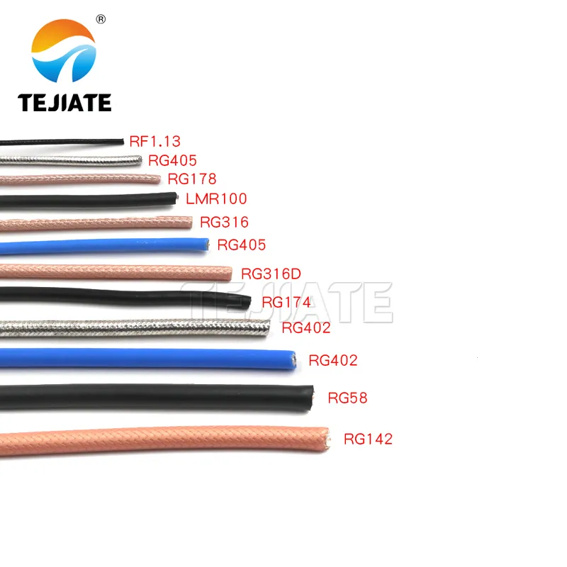
The image displays TEJTE’s full SMA cable lineup, including RG174, RG316, LMR200, and LMR240 assemblies. Each cable maintains 50Ω impedance and high shielding for reliable use in routers, CPEs, and industrial RF setups.
Cable selection is the foundation of a reliable RF chain.
Every engineer starts here, because your coax determines not only how much signal gets through but also how long the connection will last.
Each 50-ohm line has the same nominal impedance, but its dielectric, braid, and jacket control how it behaves under heat, flex, and power.
For example, the RG316 cable and RG58 cable may look similar in diameter, yet they couldn’t be more different in practice—one bends like a wire harness, the other prefers to stay put inside a rack.
Below is a data-driven comparison based on TEJTE-verified specifications, showing how each option performs in real-world conditions:
| Cable Type | Impedance (Ω) | Attenuation @ 2.4 GHz (dB/m) | Min Bend Radius (mm) | Temp Range (°C) | Jacket / Insulation |
|---|---|---|---|---|---|
| RG316 cable | 50 | 1.46 | 15 | -55 ~ 150 | FEP jacket / PTFE insulation |
| RG58 cable | 50 ± 2 | 0.93 | 50 | -20 ~ 70 | PVC jacket / solid PE dielectric |
| LMR-200 | 50 | ~0.39 | 25 (static) / 50 (dynamic) | -20 ~ 80 | Foam PE + PVC jacket |
| LMR-240 cable | 50 | ≥0.32 | 30 (static) / 61 (dynamic) | -20 ~ 80 | Foam PE + PVC jacket |
The RG316 cable is the flexible workhorse—its silver-plated copper conductor and PTFE insulation handle up to 150 °C while maintaining stable impedance.
It’s ideal when space is tight or when the assembly needs to move, such as inside a drone or RF test enclosure.
By contrast, the RG58 cable favors structure over flexibility.
Its solid PE dielectric keeps attenuation low (around 0.93 dB/m @ 2.4 GHz) but resists tight bends, so it’s better suited for fixed indoor links or rack-mounted devices.
Meanwhile, LMR-200 and LMR-240 represent the new generation of low-loss coax.
With foam PE cores and dual shielding (aluminum foil plus tinned copper braid), they reduce attenuation to 0.32–0.39 dB/m at 2.4 GHz—almost half that of RG58.
If you’re running an outdoor antenna line longer than 2 m, one of these is usually worth the extra stiffness.
How long can your SMA to SMA cable be before loss breaks the link?
Signal power shrinks exponentially with length.
Every meter adds attenuation, and every connector adds its tiny penalty.
From TEJTE’s verified connector drawings, an SMA plug shows ≤ 0.15 dB insertion loss @ 6 GHz, so two ends already cost ≈ 0.3 dB.
Let’s model this at 2.4 GHz:
| Cable | Loss (dB/m) | Connector loss (dB/2 ends) | 3 m total loss (dB) |
|---|---|---|---|
| RG316 | 1.46 | 0.3 | ~ 4.7 |
| RG58 | 0.93 | 0.3 | ~ 3.1 |
| LMR-200 | 0.39 | 0.3 | ~ 1.5 |
| LMR-240 | 0.32 | 0.3 | ~ 1.26 |
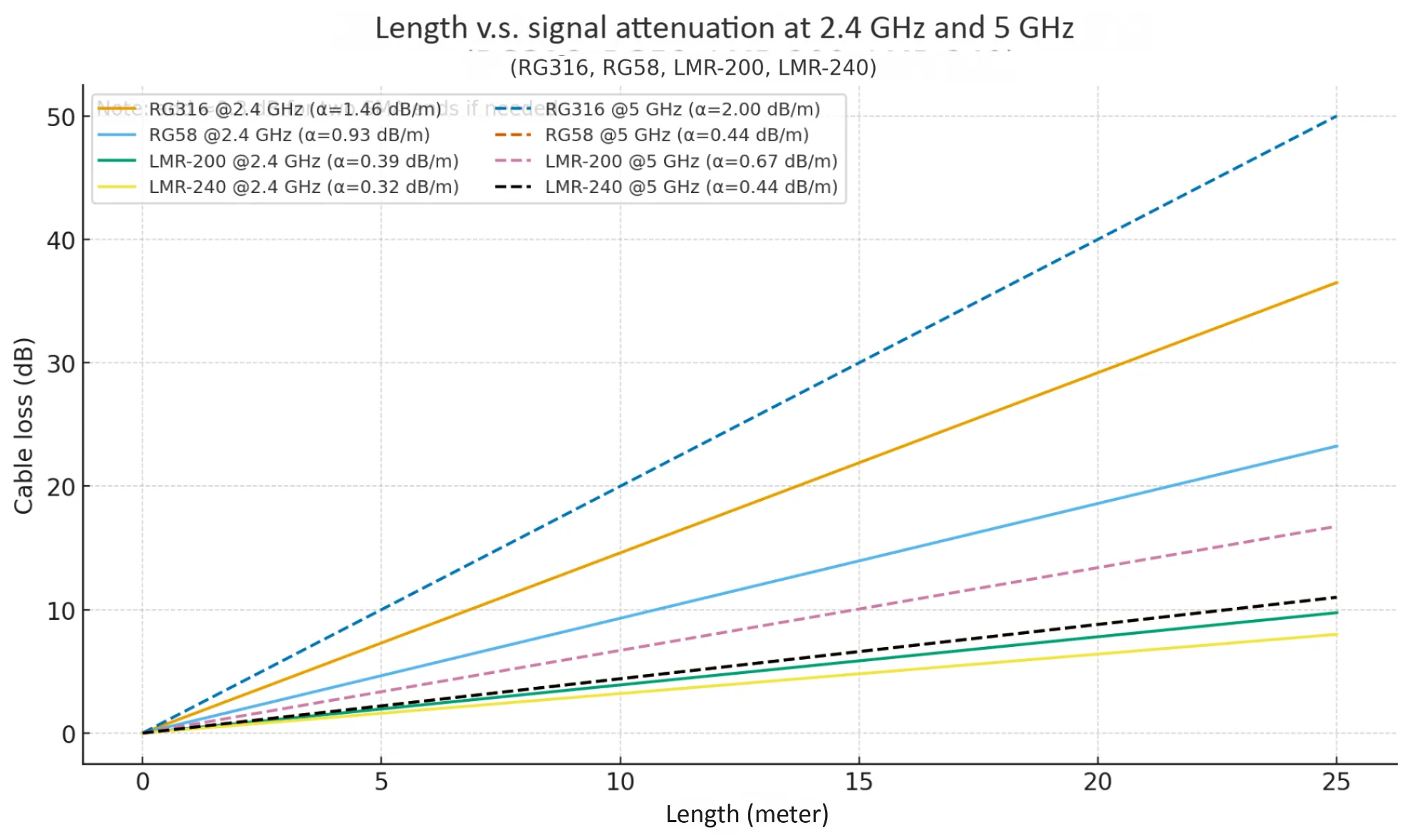
The chart quantifies total signal loss including connector insertion loss. TEJTE’s verified data shows that a 3 m RG316 cable causes ≈4.7 dB total loss, while LMR-240 limits it to ≈1.26 dB at 2.4 GHz.
Now compare that to your system’s RSSI margin.
If a 5 GHz link budget allows only 3 dB loss, RG316 won’t cut it beyond 2 m.
You’d either shorten the run or step up to LMR-200.
Add connector/adapter loss and keep total return loss acceptable
Each SMA connector adds mismatch and resistive loss.
TEJTE’s gold-plated brass housings and beryllium-bronze sockets maintain a VSWR ≤ 1.10 @ 6 GHz, equivalent to about 26 dB return loss.
Stack multiple adapters—say SMA to RP-SMA to N to SMA—and that figure doubles in reflection.
Whenever possible, replace adapter chains with a single SMA jumper cable.
Do you need male-to-male or male-to-female for this chain?
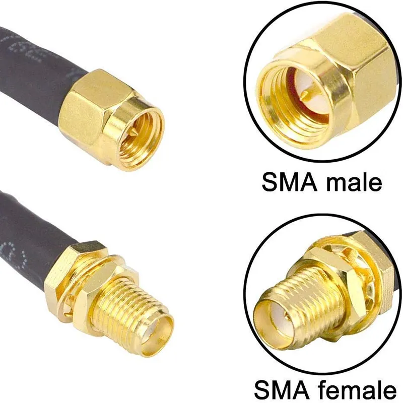
The image shows a TEJTE SMA male-to-female connector assembly, used to link device ports or antennas. Gold-plated brass and beryllium-bronze contacts ensure ≤0.15 dB insertion loss @ 6 GHz and reliable 50Ω impedance matching.
Connector gender may sound trivial until you face an install where nothing mates.
SMA-M to SMA-M jumpers link two female bulkheads (typical in test benches).
SMA-M to SMA-F works between a device port and an antenna pigtail.
Using the wrong pair not only wastes time—it risks damaging threads if you force a reverse-polarity SMA onto a standard one.
Fast gender check to avoid SMA to RP-SMA mix-ups
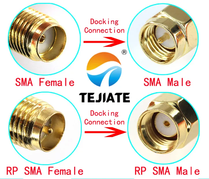
This image clarifies the differences between standard SMA and reverse polarity (RP-SMA) connectors, including gender and pin configuration, to ensure correct mating in RF systems.
Here’s the trick:
- Standard SMA-M: external threads + center pin.
- SMA-F: internal threads + center socket.
- RP-SMA-M: external threads but no center pin.
- RP-SMA-F: internal threads but with pin.
Most Wi-Fi routers use RP-SMA female ports, meaning you need an SMA male to female cable if the antenna has a standard male plug.
TEJTE’s catalog lists both types under one series, preventing mismatched orders.
When a short SMA jumper cable is better than multiple adapters
Every adapter introduces two new interfaces, each with tiny VSWR reflections.
Instead of chaining SMA to BNC to N to SMA, choose a single custom SMA jumper cable cut to the needed length.
TEJTE supplies 0.5 m to 5 m assemblies on RG316, RG58, LMR-200 and LMR-240, all tested for ≤ 0.15 dB/connector and VSWR ≤ 1.10.
That’s cleaner, lighter, and mechanically sturdier—especially when panels vibrate or shift.
How do you connect an SMA RF cable to a wireless access point safely?
A secure SMA connection is more than just twisting threads together. Each mating cycle affects return loss, shielding, and mechanical life. Following proper installation practice ensures that your 50-ohm SMA to SMA cable keeps both ports intact.
Start by confirming connector gender and polarity—many Wi-Fi access points use RP-SMA ports. Attaching a standard SMA male can feel like it fits, but it will never make electrical contact. Cross-threading also deforms the nut, increasing VSWR. Always match the gender and polarity before torqueing.
Torque sequence, ESD precautions, and strain relief
Use a calibrated SMA torque wrench (4–8 in·lbf for brass connectors) instead of pliers or fingers.
Over-tightening can crack the PTFE insulator, while under-tightening causes micro-arcing.
TEJTE’s gold-plated brass and beryllium-bronze SMA interfaces achieve their rated ≤ 0.15 dB insertion loss @ 6 GHz only when tightened to spec.
Before handling open ports, discharge static from your body—especially when connecting to routers or SDR modules with sensitive front-ends. A small wrist strap or conductive mat is enough to prevent ESD spikes that might burn the LNA.
Once connected, anchor the cable so its weight or vibration doesn’t stress the connector.
Use a nylon clamp or velcro tie within 5 cm of the plug.
When a right-angle SMA is used on the board (common in TEJTE’s SMA-KWE 8.5 mm bend-type connectors), route the coax downward with a gentle curve instead of a sharp pull—keeping the strain off the PCB pad.
Quick acceptance: continuity + spot VSWR / return-loss checks
Even a new cable can be bad if crimped wrong or overheated during soldering. A simple ohmmeter check helps:
- Center pin to center pin: near 0 Ω
- Shield to shield: near 0 Ω
- Pin to shield: open circuit
After continuity, a portable VSWR meter (or a network analyzer if available) should read ≤ 1.20 across 2.4–6 GHz.
TEJTE technicians typically test each assembly before packing; the same check can be repeated in the field to ensure connector cleanliness and plating quality.
For users extending factory routers, see the related post SMA Extension Cable Guide: Length, Signal Loss & Outdoor Setup for more safety notes on torque, strain relief, and ingress sealing.
Should you choose straight or right-angle ends for tight spaces?
Choosing between straight and right-angle connectors looks cosmetic until you try to close the housing.
In dense racks, FPV drones, or small enclosures, connector geometry decides whether your SMA jumper cable survives repeated bending.
Straight connectors transmit power most efficiently—the current flow is axial, minimizing field disturbance. They also handle torque better because force distributes along the thread. Use straight-through SMA-KE female bulkheads when the panel is flush and space allows the cable to exit freely.
Right-angle versions such as SMA-KWE 8.5 mm bend are lifesavers where vertical clearance is short.
Their side exit reduces bending moment on the coax.
TEJTE’s right-angle SMA female designs maintain ≤ 0.15 dB insertion loss and VSWR ≤ 1.20 up to 6 GHz—impressive given the 90-degree geometry.
Clearance, side-load risk, and repeated-mating durability
Every time you bend the coax right after the connector, you introduce side-load.
RG316, with its 15 mm minimum bend radius, tolerates moderate flexing.
LMR-200 and LMR-240 are stiffer; bending below 25 mm can cause shield fracture.
If your design demands frequent disconnection—say, lab analyzers or modular antennas—prefer straight ends and leave routing slack.
For fixed installations (rack gear, telemetry boxes), right-angle male-to-female assemblies reduce cable strain and help manage depth behind the panel.
Rack gear vs drone / FPV frames: real-world routing tips
- Rack mounts: keep cables vertical for gravity-neutral routing; torque to 5 in·lbf max.
- FPV drones: use RG316 or RG178 for flexibility; secure with hot glue or zip tie to absorb vibration.
- Outdoor antennas: always loop the cable downward before entry (the “drip loop”) to prevent water travel.
- Portable test kits: select LMR-200 pigtails—they balance strength and modest bendability.
When possible, design your harness layout around connector type rather than forcing a straight cable to do an angle’s job.
Will outdoor routing require UV / ingress protection and drip loops?
Absolutely. Any SMA to SMA RF cable exposed to sun, rain, or vibration needs protection against UV degradation and moisture ingress.
Even a few drops creeping through the threads can oxidize the brass and raise return loss by > 2 dB.
Outdoor reliability is less about the connector spec sheet and more about how you route and seal it.
Weather boots, O-rings around bulkheads, and grommet choices
TEJTE’s IP67 SMA bulkhead connectors use silicone rubber O-rings (6164 / 6126) and brass gold-plated housings to keep out dust and humidity.
For field cables, add a UV-sealed SMA boot that covers the hex nut entirely; it prevents standing water from wicking into the thread.
Use rubber grommets where the cable passes through metal panels—PVC jackets can chafe under vibration.
If you’re routing LMR-240 outdoors, its black PVC sheath already contains UV stabilizer, but periodic inspection is still wise.
After every temperature cycle (summer-to-winter), re-torque the external connectors to their rated 4–8 in·lbf and check for greenish oxidation on the nut—an early sign of moisture.
Service slack and re-torque intervals after temperature cycling
Provide at least 10 cm of service loop behind every bulkhead.
That small extra length absorbs thermal expansion, preventing connector pullout.
Outdoor LMR runs expand about 1 mm per meter per 10 °C change—tiny, but cumulative on long cables.
Technicians often schedule re-torque every 6 months, especially in coastal or industrial sites where salt fog accelerates corrosion.
A light coat of dielectric grease on the threads improves both torque feel and long-term sealing.
Finally, always form a drip loop below the entry point. Water obeys gravity—if the cable drops before rising into the enclosure, moisture drips away rather than flowing inside.
This single loop has saved countless radios from failure.
With careful connector handling, proper routing, and periodic checks, a well-made SMA to SMA cable assembly can deliver stable RF performance for years—even outdoors at 6 GHz.
For real-world examples of sealing and installation, TEJTE’s engineers detail further techniques in related posts under the RF Cables Hub.
Order in one pass: which SMA to SMA cable SKU matches your use case?
Selecting an SMA to SMA cable isn’t only about choosing a length that reaches—it’s about matching loss, flexibility, connector type, and environment.
One size never fits all: a short RG316 jumper might be perfect on your test bench but useless for an outdoor antenna run.
To make decisions faster, TEJTE uses a standardized part numbering system. Each model number encodes everything—from conductor and jacket to gender and waterproof options.
Below is the enhanced SMA–SMA Cable Selection Matrix, now including a “Use Case” column for quick reference.
| Ends | Cable Type | Frequency (GHz) | Length (m) | Est. Total Loss (dB) | Outdoor Rating (UV / Boot) | Use Case | Suggested TEJTE P/N |
|---|---|---|---|---|---|---|---|
| SMA-M to SMA-M | RG316 | 2.4 | 0.5 | ~1.03 | Y (IP67 boot optional) | Lab testing, tight enclosures, FPV builds | SMA-M/M-RG316-0.5M |
| SMA-M to SMA-M | RG316 | 2.4 | 1.0 | ~1.76 | Y | Wi-Fi modules, IoT routers, PCB link testing | SMA-M/M-RG316-1M |
| SMA-M to SMA-M | LMR-200 | 5.0 | 2.0 | ~1.4 | Y | Outdoor access point or small base-station feedline | SMA-M/M-LMR200-2M |
| SMA-M to SMA-M | LMR-240 | 5.0 | 3.0 | ~1.65 | Y | Rooftop or tower link, long antenna run | SMA-M/M-LMR240-3M |
| SMA-M to SMA-F | RG58 | 2.4 | 1.0 | ~1.23 | N (Indoor PVC) | Indoor patch panels, bench gear extension | SMA-M/F-RG58-1M |
| SMA-M to SMA-F | LMR-240 | 5.0 | 5.0 | ~2.6 | Y (UV-rated jacket + IP67-sealed O-ring 6164) | Outdoor router to antenna jumper, IP67-sealed | SMA-M/F-LMR240-5M |
How to read it
- Ends → define your connection chain.
Two female ports? Go SMA male-to-male. Connecting a router to an antenna? You’ll want an SMA male-to-female cable.
- Cable Type → each serves a role: RG316 for compact setups, RG58 for economical short runs, and LMR-240 when you want the lowest possible loss.
- Outdoor Rating → the “Y” mark means UV-stable jacket and optional IP-rated SMA boot sealing, ensuring your feedline survives rain and sunlight.
- Use Case → shows real-world context so you don’t need to guess whether it fits a bench or a rooftop.
Integrating connectors and adapters
Every cable in TEJTE’s lineup follows the same mechanical interface: ¼-36 UNS-2A threads with precision-matched SMA connectors.
That means you can mix straight, right-angle, or bulkhead versions freely without impedance mismatch.
When joining panels or enclosures, pair SMA-KWE female bulkheads with SMA-J male plugs, then seal the interface using silicone O-rings (6164 / 6126)—the same spec used in TEJTE’s IP67 connector assemblies.
This combination keeps moisture out even after hundreds of temperature cycles.
Each finished SMA to SMA cable assembly is torque-tested between 4–8 in·lbf, visually inspected for plating uniformity, and verified for VSWR ≤ 1.10 @ 6 GHz.
That level of detail matters when you expect 500 mating cycles or more.
If your setup mixes connector families—say SMA to N or RP-SMA to SMA—you can consult TEJTE’s SMA Adapter Guide: Selection, Sealing & Ordering for recommended adapter chains and loss considerations.
Estimate loss instantly before you cut the cable?
Every RF engineer has had this moment—you finish crimping the cable ends perfectly, only to realize the signal budget no longer works.
That’s why a quick cable loss calculator is worth keeping close.
It’s a simple tool that can prevent wasted assemblies and late-night troubleshooting sessions.
A fast calculation before you cut the line often saves both time and materials.
You don’t need a full network analyzer—just an attenuation reference and a basic Quick Loss Calculator based on your chosen coax type.
Below is a practical version built from TEJTE’s verified attenuation data across RG316, RG58, LMR-200, and LMR-240.
Formula:
[
Loss_{total} (dB) = α(f, cable) × Length + ΣLoss_{connectors}
]
Where α(f, cable) is the attenuation per meter at a given frequency,
and each SMA connector typically adds ≈ 0.15 dB (up to 6 GHz).
| Cable Type | α @ 2.4 GHz (dB/m) | α @ 5 GHz (dB/m) | Example (3 m) Loss (dB) | Connector Loss (dB) | Total Loss (dB) |
|---|---|---|---|---|---|
| RG316 | 1.46 | 2.15 | 4.38 | 0.30 | 4.68 |
| RG58 | 0.93 | 1.80 | 2.79 | 0.30 | 3.09 |
| LMR-200 | 0.39 | 0.55 | 1.17 | 0.30 | 1.47 |
| LMR-240 | 0.32 | 0.45 | 0.96 | 0.30 | 1.26 |
Why this matters
Every 3 dB of loss cuts your transmitted power in half.
So even if the math looks small, it can define whether your link margin survives at 5 GHz or not.
In one field case, replacing a 3-meter RG316 cable with LMR-200 improved signal strength by over 5 dB—enough to double throughput on a test router.
The cable loss calculator makes this kind of decision data-driven, not guesswork.
Use it as a habit before fabrication, especially for systems running over 4 GHz or where the path loss is already tight.
Many TEJTE technicians keep a laminated version of this calculator in their toolkits.
And if you’re always on the move, you’ll soon find it inside TEJTE’s upcoming online RF cable tools section.
Practical example
Imagine connecting a 5 GHz router to an outdoor antenna 3 meters away with LMR-200.
At 5 GHz, loss ≈ 0.55 dB/m × 3 = 1.65 dB, plus 0.3 dB for connectors → ≈ 1.95 dB total—comfortably below the 3 dB safe limit.
Try the same run with RG316, and the result jumps to about 6.75 dB, wiping out nearly three-quarters of your signal power.
In setups like this, it’s almost always smarter to use the calculator first than to re-crimp later.
Mini Summary — Turning data into real-world reliability
By now, you’ve seen how every 50-ohm coax cable behaves differently once installed—each bend, connector, or mismatch adds up in ways that spreadsheets rarely predict.
That’s exactly why seasoned engineers rely on a cable loss calculator before committing to a layout.
It turns abstract dB figures into something you can feel: stronger RSSI, cleaner modulation, and fewer unexplained disconnects.
Still, good data alone won’t guarantee long-term reliability.
Installation practice, sealing, and torque discipline matter just as much as the coax you pick.
A perfectly chosen SMA to SMA cable can still fail early if it’s bent past its rated radius or left unsealed under UV and moisture.
In our experience at TEJTE, engineers who double-check their cable runs with a cable loss calculator, then torque and seal properly, report years of stable 5 GHz performance—even in coastal weather or vibration-heavy environments.
On the other hand, skipping a single O-ring or overtightening one nut can undo all that precision in days.
So before wrapping up, let’s address the practical questions that RF installers, test engineers, and network integrators ask most often when working with SMA jumper cables and other 50-ohm RF assemblies in the field.
Frequently Asked Questions
1. What is the maximum practical distance for an SMA cable between an antenna and a router at 5 GHz?
With LMR-240, 5 m yields ≈ 2.6 dB loss including connectors—acceptable for most routers.
Beyond 8 m, use N-type or ½-inch low-loss coax instead.
For portable setups, keep SMA runs under 3 m and relocate the radio closer to the antenna.
2. How do I connect an SMA RF cable to a wireless access point without damaging the ports?
Always align threads, hand-tighten, then torque gently using a SMA torque wrench.
Never twist the cable body.
Check polarity—many Wi-Fi APs use RP-SMA female ports requiring SMA-male-to-female jumpers.
3. Which cable group works with SMA connectors—RG316, RG58 or LMR—and when should I pick each?
- RG316: high-flex, short runs ≤ 1 m in tight spaces.
- RG58: affordable, moderate loss for indoor patching.
- LMR-200/240: low-loss options for outdoor or longer runs up to 6 GHz.
Compare full specifications on the RF Cables Guide.
4. Can I use an SMA cable for ham radio on UHF, and what loss should I expect?
Yes—SMA jumpers work well up to 1 GHz UHF.
Expect roughly 0.5–1 dB/m for RG316 and 0.3 dB/m for LMR-200.
For higher-power HF/UHF use, confirm the connector’s 1000 V RMS rating and solid shield termination.
5. How do I attach an SMA plug to coax, and when should I buy a pre-terminated cable instead?
Crimping demands precise strip lengths and hex-die sizes.
A mis-crimp can raise VSWR or damage the PTFE insulator.
Unless you have professional tooling, buy factory-terminated assemblies like the
SMA to SMA Cable RG316 2 m—each tested for ≤ 1.10 VSWR and 0.15 dB connector loss.
6. Should I choose male-to-male or male-to-female for a bench setup vs an outdoor antenna?
Bench gear usually has female ports, so male-to-male works best.
Outdoor antennas often use female bulkheads—select a male-to-female jumper instead.
Always confirm thread direction and pin gender to avoid RP-SMA mix-ups.
7. Why are many SMA cables sold in short lengths, and when should I relocate the radio instead of extending?
Because loss rises linearly with length, most SMA assemblies stop at 3–5 m.
Beyond that, signal degrades faster than it can be amplified.
It’s usually smarter to move the radio closer to the antenna and run Ethernet for data.
For guidance on outdoor placement and sealing, check TEJTE’s
Bonfon Office Building, Longgang District, Shenzhen City, Guangdong Province, China

A China-based OEM/ODM RF communications supplier
Table of Contents
Owning your OEM/ODM/Private Label for Electronic Devices andComponents is now easier than ever.
