SMA Right Angle Connector: Selection, Mounting & PCB Guide
Oct 5,2025
Introduction

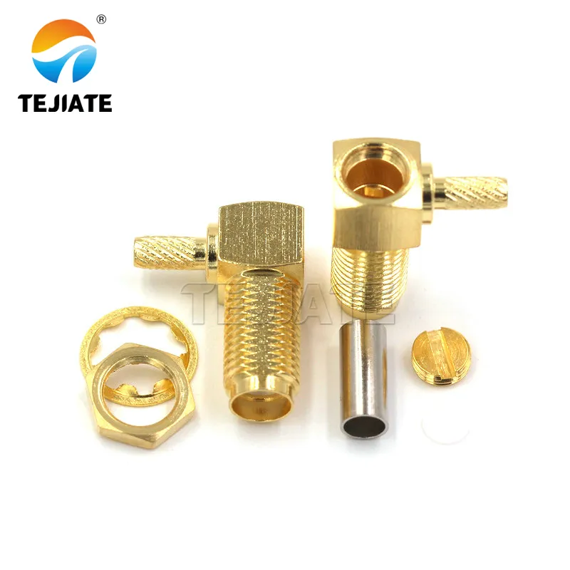
The image introduces SMA right-angle connectors used when space is limited or when coax cables must be redirected without exceeding bend radius. It reflects TEJTE’s standard SMA-JKW model, rated up to 6 GHz.

The image highlights how right-angle SMA connectors help maintain cable integrity within the minimum bend radius, preventing long-term impedance drift and reflection loss at 5.8 GHz.
Choosing the right connector may sound like a small detail, but for RF engineers, it often makes or breaks the system. The sma right angle connector is one of those parts that shows up when space is tight, when cable bends need control, or when serviceability matters. Unlike a straight SMA, the right-angle design changes not only the physical routing but also the way you plan impedance, torque, and reliability.
In this guide, we’ll look at the trade-offs between right-angle and straight connectors, how to confirm PCB form factors, what kind of loss to expect, and how to keep a clean 50 ohm sma cable chain. You’ll also find practical checklists—from ordering specs to a 5-minute IQC inspection—so that engineers and buyers can make confident decisions without guesswork.
When should I choose a right-angle SMA instead of a straight one?
Space constraints and bend-radius limits
Every coax cable comes with a minimum bend radius, and ignoring it is risky. Push the cable too tight and the braid may deform, while the dielectric can develop tiny cracks. At 900 MHz this might look harmless, but by 5.8 GHz the return loss will tell a different story.
- In compact IoT gateways or smart-home hubs with <20 mm depth, a straight SMA simply doesn’t clear the board.
- Choosing a pcb mount sma connector in right-angle form solves the clearance issue and keeps the coax stress-free.
Real-world parts underline this point. TEJTE’s SMA-JKW right-angle model, for instance, operates from –65 °C to +165 °C, shows insertion loss ≤0.15 dB at 6 GHz, and survives 500+ mating cycles. Its contact resistance ≤5 mΩ and insulation resistance ≥5000 MΩ ensure low-loss performance even after repeated use.
Adapter vs short jumper trade-offs

The photo compares a right-angle SMA connector against a straight connector plus 20 mm jumper, showing how extra joints add 0.1–0.2 dB loss, while a right-angle contributes only ~0.08 dB.

The image shows an extended-body SMA right-angle connector, designed to increase mechanical clearance between PCB and housing. It ensures easier torqueing and safer cable bending in dense enclosures while maintaining ≤0.15 dB insertion loss at 6 GHz.
It’s a fair question: why not stick with a straight connector and add an sma adapter or a short jumper cable? Technically it works, but each joint adds loss. A straight plus a 20 mm jumper might introduce 0.15–0.20 dB at 2.4 GHz, while a single right-angle connector typically contributes only ~0.08 dB. That small difference adds up quickly in cascaded systems.
For production equipment, the right-angle SMA keeps designs compact and predictable. On the other hand, test setups often prefer the straight + jumper option since jumpers are cheap to replace and convenient during troubleshooting. TEJTE discusses this trade-off further in its SMA Adapter Selection Guide, a useful reference for labs balancing flexibility with performance.
How do I confirm my PCB form factor (edge-mount, vertical, flange)?
Differences among SMA PCB connectors and panel mounts
1.Edge-mount sma pcb connector

The image depicts a through-hole SMA connector with vertical coax exit, ideal for multi-layer or sensor boards, featuring ≤ 0.15 dB loss @ 6 GHz and 1000 V RMS isolation.
- Mounted flush to the PCB edge.
- Provides the cleanest 50 Ω launch, which is why RF evaluation boards almost always use it.
- TEJTE’s edge-mount series shows contact resistance ≤5 mΩ, insulation resistance ≥5000 MΩ, and VSWR ≤1.20 up to 6 GHz—numbers that hold steady across hundreds of mating cycles.
2.Through-hole or vertical pcb mount sma connector

The image shows a four-hole flange SMA connector fixed with screws, offering solid mechanical stability and secure grounding, widely used in test gear and industrial radios.
- Leads pass through plated holes and solder into the board.
- Excellent when you need the coax to exit vertically, for example in stacked PCB modules or sensor boards.
- These types typically handle 1000 V RMS withstand voltage and have insertion loss ≤0.15 dB @ 6 GHz, which makes them robust for high-isolation designs.
3.Flange / panel mount SMA

The image highlights a right-angle waterproof SMA connector with silicone O-ring, suitable for outdoor antennas and automotive electronics, rated –65 °C to +165 °C with ≤ 0.15 dB loss @ 6 GHz.
- Secured to the enclosure front panel with nuts and washers.
- Rugged and service-friendly, ideal for industrial radios or test gear.
- Many models include O-ring grooves for sealing, extending usability in outdoor or dusty environments.
Tip: if your design uses a front-panel connector, always double-check the panel cutout dimensions against the supplier’s drawing. Even a 0.1 mm error can make the nut misalign.
Grounding for edge-mount parts
With an sma pcb edge mount connector, grounding is not optional. TEJTE’s recommended footprint specifies via fences at 1 mm pitch plus carefully dimensioned anti-pad openings. This preserves the 50 Ω transition from connector pin to microstrip.
Skip these details, and the price shows up in S11 plots. At 5.8 GHz, a poor ground return can raise VSWR enough to break Wi-Fi links. That’s why many engineers rely on TEJTE’s SMA Connector PCB Layout guide, which provides pad dimensions, keep-out rules, and practical layout tricks.
How much loss/VSWR does a right-angle add, and how do I compensate?
Loss/VSWR estimator (n, IL_stage, bands 0.9/2.4/5.8 GHz)
| Frequency | Connection Type | Typical IL per stage (dB) | Cascade Limit |
|---|---|---|---|
| 900 MHz | Right-angle | 0.05 | ≤4 |
| 2.4 GHz | Right-angle | 0.08 | ≤3 |
| 5.8 GHz | Right-angle | 0.12 | ≤2 |
| 2.4 GHz | Straight + jumper | 0.10-0.15 | ≤2 |
Pad/keep-out tuning, via fences, torque
The key to keeping performance under control is disciplined PCB layout and assembly:
- Pads and anti-pads: Oversized pads increase capacitance and disturb the transition. Always match the footprint provided by the supplier.
- Via fences: Adding ground vias close to the signal pad (about 1 mm spacing) helps maintain return paths. TEJTE’s right-angle footprints recommend this spacing for consistent 50 Ω launches.
- Torque: Don’t guess. Apply 8 lb·in for brass-gold SMA connectors and 12 lb·in for stainless steel versions. Under-tightening causes poor mating; over-tightening risks cracking the dielectric.
For engineers who want layout-specific advice, TEJTE’s SMA PCB Connector Selection & Mounting guide covers pad design, solder profiles, and torque ranges in detail.
How do I maintain a clean 50-ohm chain?
Launch optimization and cabling (50-ohm coax)
Your sma connector pcb layout plays a big role here. On a standard 1.6 mm FR-4 board, the controlled trace width for 50 Ω impedance can be as small as 2.8 mm, depending on dielectric constant. A deviation of just 0.2 mm may drop return loss below 20 dB at 2.4 GHz.
Carefully designed pads, anti-pads, and solder masks help maintain the correct transition. TEJTE’s pcb mount sma connectors are built with these tolerances in mind, but designers still need to implement them correctly.
On the cable side, never compromise—use a verified 50 ohm sma cable. TEJTE’s coax assemblies, tested to 0–6 GHz and more than 500 mating cycles, ensure stable impedance. By contrast, using a 75 Ω CCTV cable “because it fits” is a classic mistake. A quick VNA sweep will instantly reveal the mismatch spike. For detailed coax selection tips, TEJTE’s RF Coaxial Cable Guide is worth checking.
Avoid unnecessary SMA To BNC adapters
It’s tempting in labs to grab an sma to bnc adapter for convenience—especially when connecting to scopes or legacy instruments. For short-term testing, that’s fine. But in a production chain, each adapter adds discontinuity. At 5.8 GHz, even one BNC adapter can raise VSWR by 0.1–0.2, which eats into your system margin.
If you absolutely need an adapter, limit its use to test benches and document it. For deployed products, keep the path clean: connector to coax, 50 ohm all the way.
Which materials and platings should I specify?
Brass-gold vs stainless, torque windows
- Brass with gold plating: This is the go-to option in most commercial products. Brass is light and affordable, and a gold finish keeps contact resistance low (≤5 mΩ typical). Torque spec: around 8 lb·in. TEJTE’s SMA-KY series is a good reference, with insertion loss ≤0.15 dB up to 6 GHz and plating designed for ≥500 mating cycles.
- Stainless steel: Heavier but extremely rugged, stainless shells handle repeated torqueing without deformation. Torque spec: about 12 lb·in. TEJTE’s stainless SMA-IPEX assemblies combine PTFE insulation and steel housings for stability in high-cycle test setups.
In practice, stainless feels almost indestructible on the bench, while brass-gold is usually the smarter choice inside routers, IoT hubs, or gear that only gets assembled once.
Sealing and anti-loosening for outdoor/vibration

The image highlights a waterproof SMA connector featuring a silicone O-ring, providing environmental sealing for outdoor radios, CPEs, and antenna feedthroughs. The O-ring maintains stable impedance under vibration and temperature cycles from –65°C to +165°C.
Mechanical durability is only part of the story. For outdoor radios, automotive electronics, or high-vibration equipment, sealing and anti-loosening features are just as important:
- O-rings or silicone gaskets: Keep moisture out, preserve impedance stability, and protect against corrosion.
- Lock nuts or thread-lock coatings: Prevent gradual loosening under vibration.
A good example is TEJTE’s SMA-KY-1.5 with waterproof cap, rated –65 °C to +165 °C. Even under vibration tests (Method 213), it maintains <0.15 dB loss at 6 GHz. For additional practices on sealing and outdoor use, check TEJTE’s SMA Antenna Extension Cable Guide.
How do I solder and inspect a right-angle PCB SMA?
Reflow/hand-solder specs and visual/pull criteria
For reflow soldering, aim for a peak temperature of 240–250 °C (lead-free) and keep the preheat ramp under 3 °C/s. Go too fast, and the PTFE dielectric can blister.
For hand soldering, use a tip around 350 °C with adequate flux. Limit dwell time to about 3 seconds per pin. The goal is to wet the joint fully without overheating the housing.
After soldering, inspection is key:
- Cleaning: Remove flux residues; they can form leakage paths.
- Wetting: Good fillets look smooth and continuous, not grainy.
- Pull test: TEJTE’s SMA-JKW right-angle connector is specified for ≥0.28 N pin retention and ≥50 N leg pull strength. These numbers set a baseline for quality.
Common defects and fixes
Even careful teams see defects. Some of the usual suspects include:
- Eccentric pins: Usually caused by poor jigging. Off-center pins damage mating jacks—reject or rework immediately.
- Poor wetting: Often due to low flux or tip temperature. Reapply flux and reflow to fix.
- Lifted pads: A classic result of overheating. In production, epoxy underfill beneath connector legs helps avoid pad lift during rework.
For more detailed footprint guidelines and soldering advice, TEJTE’s PCB Connector Selection & Mounting guide provides pad dimensions, anti-pad rules, and torque specs.
How do I solder and inspect a right-angle PCB SMA?
Reflow/hand-solder specs and visual/pull criteria
For reflow soldering, aim for a peak temperature of 240–250 °C (lead-free) and keep the preheat ramp under 3 °C/s. Go too fast, and the PTFE dielectric can blister.
For hand soldering, use a tip around 350 °C with adequate flux. Limit dwell time to about 3 seconds per pin. The goal is to wet the joint fully without overheating the housing.
After soldering, inspection is key:
- Cleaning: Remove flux residues; they can form leakage paths.
- Wetting: Good fillets look smooth and continuous, not grainy.
- Pull test: TEJTE’s SMA-JKW right-angle connector is specified for ≥0.28 N pin retention and ≥50 N leg pull strength. These numbers set a baseline for quality.
Tip: even if you don’t own a pull tester, a simple spring gauge works in prototypes. It’s better than assuming the solder joint will hold.
Common defects and fixes
Even careful teams see defects. Some of the usual suspects include:
- Eccentric pins: Usually caused by poor jigging. Off-center pins damage mating jacks—reject or rework immediately.
- Poor wetting: Often due to low flux or tip temperature. Reapply flux and reflow to fix.
- Lifted pads: A classic result of overheating. In production, epoxy underfill beneath connector legs helps avoid pad lift during rework.
For more detailed footprint guidelines and soldering advice, TEJTE’s PCB Connector Selection & Mounting guide provides pad dimensions, anti-pad rules, and torque specs.
What specifications must I submit before ordering to avoid rework?
Specification checklist
When preparing your order, make sure to include:
- Connector type: sma right angle connector
- Gender and polarity: plug/jack, standard or RP-SMA
- Angle: right-angle vs straight
- Board termination: edge-mount or pcb mount sma connector
- Impedance: 50 Ω (don’t assume—it must be stated)
- Frequency range: specify 0–6 GHz or extended up to 18 GHz
- Housing and plating: brass with gold finish, or stainless steel
- Torque spec: 8 lb·in (brass-gold) / 12 lb·in (stainless)
- Packaging: tape-and-reel for SMT, tray for through-hole, or bulk for small runs
For engineers designing the board, attach sma connector pcb drawings and footprint details. TEJTE maintains downloadable footprints and design notes on their RF Connector product page, which reduces the risk of mismatch between board layout and the actual connector.
Documentation and traceability
Specs alone aren’t enough. A solid order package should also include:
- Certificates: RoHS, REACH, or CE as required.
- CoC (Certificate of Conformance): Ensures delivered parts meet your specs.
- Reliability data: Temperature range, insertion loss ratings, and durability cycles.
- Assembly drawings: Pad sizes, anti-pad rules, via fence layout.
Traceability is equally important. Request lot numbers and inspection records with each shipment. TEJTE supports this practice with serialized QC documentation, making it possible to track every connector back to its raw materials.
How do I perform a 5-minute incoming quality check (IQC)?
IQC quick checklist
| Item | Method | Acceptance Criteria |
|---|---|---|
| Visual inspection | Naked eye / 10× loupe | No cracks, plating smooth, no scratches |
| Thread & dielectric | Thread gauge / visual | Threads clean, dielectric centered, no burrs |
| Dimensions | Caliper / go-no-go gauge | ±0.05 mm tolerance |
| Torque test | Torque wrench | 8 lb-in (brass-gold) / 12 lb-in (stainless) |
| Continuity/insulation | Digital multimeter | <1 Ω continuity />100 MΩ insulation |
| Quick S11 sweep | VNA @ 2.4 GHz | Return loss ≥20 dB |
Common defects and actions
Even reputable suppliers can ship occasional outliers. Watch for:
- Eccentric pins: Off-center pins make mating difficult and can damage female connectors. Reject these immediately.
- Lifted pads on sma connector pcb assemblies: Usually caused by overheating during soldering. Flag for rework before they reach final assembly.
- Plating peel-off: A warning sign for corrosion or poor durability. Quarantine and request replacements.
For engineers who want a deeper checklist, TEJTE’s Complete SMA Connector Guide includes torque specs, plating tests, and environmental checks that go beyond a basic IQC.
FAQs
Will a right-angle SMA reduce bandwidth compared with a straight launch at 2.4/5.8 GHz?
Slightly, yes. Expect an additional 0.08–0.12 dB insertion loss depending on frequency. For most Wi-Fi and IoT designs, this is acceptable if you keep cascades minimal.
When should I replace a right-angle with a straight jack plus a short jumper?
If your product will be serviced often—like telecom racks—a jumper is easier to swap. For sealed or compact devices, the right-angle is more reliable.
What torque values are safe for brass-gold vs stainless right-angle SMA?
About 8 lb·in for brass-gold connectors, 12 lb·in for stainless. Using the right torque prevents both loose contacts and cracked dielectrics.
How do I lay out pad/anti-pad and via fences for a right-angle PCB SMA?
Follow the footprint drawings. TEJTE recommends via fences at ~1 mm spacing, with anti-pad openings tuned to maintain 50 Ω. More details are available in the SMA Connector PCB Layout guide.
Can I mix a 50 ohm right-angle SMA with a temporary BNC adapter in the lab?
Yes, for quick tests. But don’t leave adapters in production chains—they add ripple and degrade VSWR, especially above 2.4 GHz.
What quick IQC checks catch mis-soldered right-angle connectors?
Check solder wetting visually, run a pull test (~50 N leg strength), and if possible, do a fast S11 sweep at 2.4 GHz.
Does a right-angle connector help or hurt enclosure strain and reliability?
In most cases it helps by reducing sharp bends in the coax. But if the soldering or torque is poor, that benefit disappears.
Conclusion
The sma right angle connector is more than a mechanical workaround—it’s a design choice that influences impedance, loss, and long-term reliability. By understanding when to use right-angle vs straight, following proper sma connector pcb layout, and verifying parts with a simple IQC checklist, engineers can avoid costly mistakes.
For projects that need consistent RF performance, TEJTE offers a full range of pcb mount sma connectors, 50 ohm sma cables, and adapters. Each model comes with verified specs—like insertion loss ≤0.15 dB @ 6 GHz and 500+ mating cycles—so you can design with confidence.
Bonfon Office Building, Longgang District, Shenzhen City, Guangdong Province, China

A China-based OEM/ODM RF communications supplier
Table of Contents
Owning your OEM/ODM/Private Label for Electronic Devices andComponents is now easier than ever.
