
The sample cable fit perfectly on the open bench. Once the radio was installed inside the enclosure, the SMA coupling nut touched the sidewall, the coax left the connector at the wrong angle, and the installer had to force the cable into place.
Continuity still passed. The RF result did not.
An SMA right angle cable is often ordered as though it were simply a straight cable with a 90-degree connector added to one end. That description leaves out several details that determine whether the finished assembly can actually be installed: which port receives the elbow, where the cable exits after tightening, how much radial space the connector body consumes, and whether the first cable bend applies torque to the termination.
The RF specification also belongs to the complete assembly. Cable family, length, connector workmanship, installed bend condition, and extra interfaces all contribute to the measured result. A connector-family frequency rating alone cannot qualify the cable.
This guide focuses on complete flexible cable assemblies. Individual right-angle connector construction is covered separately in the SMA Right Angle Connector Guide, while rigid elbow configurations belong in the Right-Angle SMA Adapter Guide.
Which Port Should Receive the Right-Angle End?
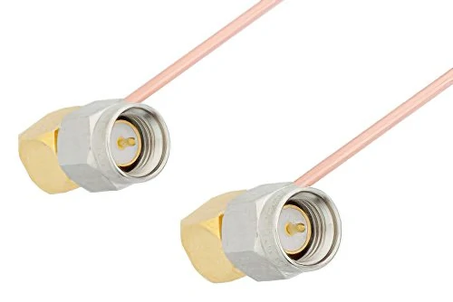
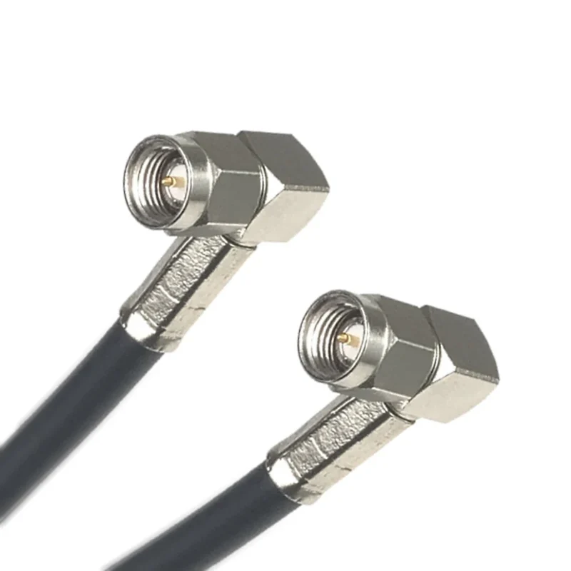
Two right-angle SMA male connectors terminated on small-diameter semi-rigid coaxial cables. The connector orientation highlights the need to specify the viewing reference, clock position, nominal angle, and allowable clocking tolerance.
Putting the elbow on the device side is common, but it is not an automatic rule.
Start by checking the real installation envelope at both ends. One port may sit behind a recessed panel, while the other faces a heat sink, antenna bracket, neighboring connector, or enclosure wall. The right-angle end belongs at the port where an axial cable exit creates the greater problem.
A typical assembly may be arranged as:
Device SMA Port→ Right-Angle SMA End→ Flexible Coax→ Straight SMA End→ Antenna or RF Equipment The opposite arrangement is equally valid:
RF Equipment→ Straight SMA End→ Flexible Coax→ Right-Angle SMA End→ Recessed Antenna Port Keeping one end straight usually simplifies assembly, inspection, and cable routing. It can also reduce ordering errors because only one elbow orientation needs to be controlled.
Decide whether both ports need elbows
A right-angle-to-right-angle cable may be useful when both ports face enclosure walls or when the cable must remain parallel to a panel. It is not automatically the most compact option.
Two elbows introduce relative clocking. The cable exits at both ends must match the installed port positions after the coupling nuts are fully tightened. A drawing that specifies two “90-degree SMA male connectors” but does not define their relative orientation is incomplete.
Use the following matrix during the initial layout review.
| Device-Side Clearance | Far-Side Clearance | Suggested Assembly |
| Limited | Open | Right angle to straight |
| Open | Limited | Straight to right angle |
| Limited | Limited | Right angle to right angle |
| Open | Open | Straight cable usually preferred |
| Unknown | Unknown | Measure both installed envelopes |
The decision should also record connector gender, standard or reverse polarity, adjacent-port interference, tool access, and the required cable exit direction.
A few millimeters of clearance can determine whether the installer can rotate the coupling nut without turning the entire cable.
How Should the Elbow Clocking Direction Be Specified?
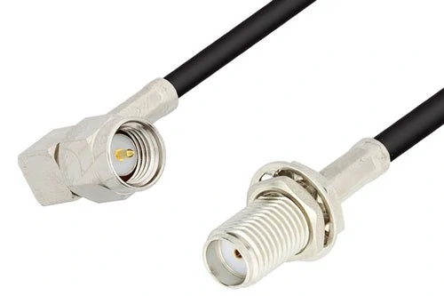
Black coaxial cable assembly with a right-angle SMA male connector on one end and a straight SMA female bulkhead connector on the other. This arrangement is useful for compact enclosures where the external interface must be secured to a panel.
“90-degree SMA cable” describes the elbow shape. I
t does not describe where the cable points.
The exit direction must be tied to a viewing reference. Without one, a supplier may interpret 3 o’clock from the mating face while the enclosure designer intended 3 o’clock when viewed from the cable side. Those two views are mirrored.
The note establishes three things:
- the viewing direction;
- the reference plane;
- the connector’s final mated condition.
Clock positions such as 12, 3, 6, and 9 o’clock are convenient for communication, but a controlled drawing should also show an angular dimension. For custom production, define the datum, nominal angle, and allowed tolerance.
Control relative clocking at both ends
For a dual-elbow assembly, specify whether the exits are:
- in the same plane;
- facing opposite directions;
- offset by 90 degrees;
- offset by 180 degrees;
- set to another project-specific angle.
Do not approve relative clocking from a product photo alone. The connector may be loose, the assembly may have been rotated for photography, or the image may have been mirrored during editing.
A simple clocking card can prevent a surprising number of sample revisions.
| Drawing Field | Required Entry |
| Viewing direction | Mating face or cable side |
| Zero reference | Drawing datum |
| End A cable exit | Angle or clock position |
| End B cable exit | Angle or clock position |
| Relative clocking | 0° / 90° / 180° / 270° |
| Angular tolerance | Project value |
| Fully mated reference | Yes or no |
| Drawing approval | Customer and supplier |
Clocking is especially important on SMA male ends. Tightening position can vary slightly with interface tolerances, so the allowed angular range should reflect the actual installation rather than an unrealistic cosmetic target.
Can the Assembly Clear the Enclosure Without Forcing the Coax?
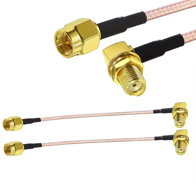
A right-angle connector reduces axial cable height, but it moves part of the assembly into the radial direction. That can solve one interference problem and create another.
Measure more than the distance from the port to the enclosure wall. The installed envelope includes:
- elbow body height;
- elbow body width;
- coupling-nut diameter;
- tool or finger rotation space;
- cable outer diameter;
- strain-relief length;
- first-bend distance;
- nearby connector spacing.
The useful numbers are the remaining margins after the connector is installed.
Axial Margin= Available Axial Height − Right-Angle Assembly Height Radial Margin= Available Radial Width− Elbow Width− Required Cable Clearance A positive calculation does not always mean the layout is safe. Small dimensional variation, connector rotation, panel tolerance, and cable movement can consume the remaining space. A nominal margin of less than a millimeter may disappear during production.
Keep the first cable bend away from the elbow
The coax still needs room after it leaves the right-angle body.
A common installation mistake is to use the elbow to save space and then immediately fold the cable backward against the termination. That reverse bend loads the ferrule, braid connection, dielectric, and center conductor. The assembly may pass its first bench test and become position-sensitive after repeated installation.
Provide a short relief section before the first major direction change. Keep the coax away from sharp enclosure edges and avoid using the closed cover as a cable clamp.
For early layout work, approximately five times the cable outside diameter can be used as a preliminary fixed-bend check. It is not a universal product specification. The selected cable manufacturer’s bend-radius requirement takes priority.
A compact RG316 assembly and a lower-loss cable with a larger jacket may use the same SMA interface while requiring very different routing space.
When Does a Flexible Right-Angle Cable Beat a Rigid Adapter?
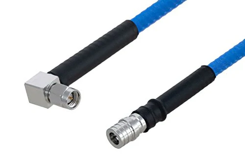
Flexible blue RF coaxial cable assembly featuring a right-angle SMA connector and a straight RF connector. The configuration illustrates how an angled cable end can reduce axial clearance requirements near an enclosure or recessed device port.
A rigid elbow changes direction at the port. A right-angle cable changes direction and bridges distance.
That distinction matters when the two ports are offset, one component moves, or production tolerances prevent perfect alignment. Flexible coax can absorb limited positional variation without transferring the entire load into the SMA interface.
Compare these two RF paths:
SMA Port→ Rigid Right-Angle Adapter→ Straight SMA Cable→ Load SMA Port→ Integrated Right-Angle SMA Cable→ Load The integrated assembly normally removes one detachable interface. That means one fewer mating point to loosen, contaminate, misidentify, or leave partially tightened.
The adapter arrangement still has valid uses. It can provide the shortest physical transition when no cable distance is needed, and the straight cable can be replaced independently. The adapter may also be rotated separately during installation, depending on the port arrangement.
Compare mechanical loading, not only loss
The lowest measured insertion loss is not the only useful criterion.
A rigid elbow connected to a stiff cable can act as a lever on the equipment port. Vibration, cable weight, or accidental pulling then reaches the SMA interface directly. A short flexible jumper can isolate some of that movement, particularly when a nearby clamp supports the cable.
| Requirement | Integrated Right-Angle Cable | Adapter Plus Straight Cable |
| Offset ports | Preferred | Limited |
| Low interface count | Preferred | Adds another interface |
| Minimum physical path | Good | Often shorter |
| Vibration isolation | Better with proper support | Usually lower |
| Independent cable replacement | Entire assembly replaced | Cable can be replaced |
| Clocking control | Must be specified | Adapter may be adjusted separately |
| Part-count control | One assembly | Multiple BOM items |
| Tight RF budget | Test complete path | Test complete path |
Neither option should be approved from geometry alone. Sweep the complete configuration across the required band, using the same adapters and routing condition planned for the final equipment.
How Much RF Margin Does the Angled Assembly Consume?
There is no single insertion-loss value for every right-angle SMA cable.
The coax contributes length-dependent attenuation. Each connector transition adds a smaller, frequency-dependent contribution. Additional adapters and damaged bends add their own penalties.
A useful engineering estimate is:
Estimated Total Insertion Loss= Cable Attenuation at Frequency × Cable Length+ Right-Angle End Allowance+ Other Connector End Allowance+ Extra Interface Loss The estimate is useful for link-budget planning, but the connector allowances should not be invented from a generic catalog statement. Use supplier data or measure a representative finished assembly.
Once the connector and interface allowance is known, a preliminary maximum cable length can be calculated:
Maximum Cable Length= (Permitted Link Loss− Connector-End Allowance− Extra Interface Loss)÷ Cable Attenuation per Unit Length Run the calculation at the highest operating frequency and at any band where the system has a particularly tight margin. A cable that is acceptable at 2.4 GHz may consume too much of the budget at 5 or 6 GHz.
Treat the rating as an assembly specification
A right-angle connector may be sold as an 18 GHz part, but that does not automatically make the terminated cable an 18 GHz assembly.
The upper usable frequency can be limited by:
- cable attenuation;
- connector geometry;
- ferrule and braid contact;
- center-pin alignment;
- soldering or crimp quality;
- cable length;
- bend condition;
- test adapters;
- required VSWR limit.
Commercial assemblies illustrate why the complete part number matters. A manufacturer may specify a particular RG316 assembly as 50 ohms, 152 mm long, fitted with two right-angle SMA plugs, and rated to 12 GHz. Those values belong together. They should not be separated into a claim that every RG316 right-angle cable supports the same frequency.
Which Coax Belongs Behind the Right-Angle Connector?
RG316 is a common starting point for compact right-angle jumpers. Its small diameter supports tight equipment layouts, and its construction is widely used for short RF connections, test fixtures, antenna leads, and internal module wiring.
It is not automatically the lowest-loss option.
A short RG316 cable can be a better mechanical choice than a thicker cable whose bend radius, connector body, and stiffness do not fit the enclosure. As length increases, attenuation may become the deciding factor.
Compare RG174, RG316, and lower-loss alternatives
RG174 may be selected where minimum diameter and easy routing matter more than attenuation or temperature margin. Its exact construction and rating still depend on the supplier.
RG58 and cables in the LMR-100, LMR-195, or LMR-200 size range can reduce attenuation in suitable configurations. The penalty is usually a larger installed envelope and a higher mechanical load on the connector.
| Selection Factor | RG174 | RG316 | Lower-Loss Coax |
| Small outside diameter | Strong option | Strong option | Usually weaker |
| Short high-frequency jumper | Review carefully | Common choice | Good when space allows |
| Longer cable path | Higher-loss risk | Calculate first | Usually preferred |
| Tight enclosure | Easier to route | Compact and practical | May be difficult |
| Temperature capability | Construction-dependent | Often a strong option | Construction-dependent |
| Right-angle termination availability | Verify | Common | Verify exact connector |
| Bend-radius burden | Lower | Moderate | Usually higher |
| Port loading | Low | Low to moderate | Higher without support |
A cable-family substitution changes more than attenuation. Confirm ferrule dimensions, center-pin design, jacket diameter, shield construction, termination tooling, minimum bend radius, and strain-relief geometry.
An SMA connector body intended for RG316 should not be fitted to RG58 simply because the front mating interface is the same.
IEC 61169-15 defines the 50-ohm SMA interface and its dimensional framework. It does not make different cable terminations or finished cable assemblies interchangeable.
How Do You Prevent the Right-Angle End From Rotating Under Load?
The coupling nut should rotate during mating. The cable and elbow body should not be used as the tightening handle.
When an installer turns the coax to tighten the connector, torsion travels into the termination. The braid may move inside the ferrule, the cable may remain pre-twisted, and the elbow may point away from the intended route after the nut reaches torque.
The installation instruction should be direct:
- Align the connector without twisting the cable.
- Support the right-angle body.
- Rotate the coupling nut only.
- Use the connector supplier’s torque requirement.
- Confirm cable-exit direction after mating.
- Install the cable support before closing the enclosure.
A cable tie can create the same problem when it pulls sideways from a distant mounting point. Place a clamp or guide near the connector, but leave enough relief that the clamp does not sharply bend or crush the coax.
Inspect body movement during sample approval
Check for rotation at several locations:
- coupling nut relative to the mating port;
- elbow body relative to the connector interface;
- coax relative to the elbow termination;
- strain-relief boot relative to the cable;
- completed assembly while lightly loaded.
A visible rotation problem is already a mechanical rejection. Smaller movement may require an RF check. Sweep the assembly, apply controlled torsion within the expected installation range, and watch for changes in S11 or S21.
A cable that passes only while held in one position is not production-ready.
Can the Assembly Survive Motion, Vibration, and Repeated Mating?
Connector mating cycles and cable flex cycles are different life tests.
The SMA interface may remain mechanically sound while the elbow termination begins to fatigue. The opposite can also happen: the coax remains undamaged, but repeated mating wears or contaminates the contact interface.
Define the stress that matches the application. A cable installed once inside a stationary laboratory instrument does not need the same flex qualification as a vehicle antenna lead, service cable, hinged enclosure, or frequently reconfigured test fixture.
Test the cable in its installed orientation
A relaxed cable on a bench may hide the load that exists inside the product. Use a fixture that reproduces:
- connector orientation;
- cable exit direction;
- clamp location;
- minimum permitted bend;
- unsupported cable length;
- vibration direction;
- representative mating torque.
Record an initial visual inspection and VNA sweep. Apply the required mating, flex, or vibration sequence, then repeat the same measurements without changing the reference planes.
Useful acceptance fields include:
| Test Item | Initial Result | Post-Stress Result | Acceptance Basis |
| Return loss | Measured dB | Measured dB | Project minimum |
| VSWR | Measured ratio | Measured ratio | Project maximum |
| Insertion loss | Measured dB | Measured dB | Project maximum |
| Continuity | Pass or fail | Pass or fail | No interruption |
| Elbow rotation | Measured angle | Measured angle | Drawing limit |
| Cable jacket | Condition | Condition | No damage |
| Connector retention | Result | Result | Mechanical requirement |
Do not rely only on the final values. Compare the change from the initial result. A cable may technically remain inside a broad limit while showing a large post-stress shift that indicates a developing termination problem.
How Can You Prevent an SMA and RP-SMA Ordering Error?
“SMA male” does not identify an RP-SMA male.
Both may have external threads, but the center contacts are different. Standard SMA male uses a pin. RP-SMA male uses a socket. The female versions reverse the center-contact arrangement while retaining their respective thread positions.
| Interface | Thread Position | Center Contact |
| SMA male | External | Pin |
| SMA female | Internal | Socket |
| RP-SMA male | External | Socket |
| RP-SMA female | Internal | Pin |
Do not assume that every Wi-Fi radio uses RP-SMA or that every test instrument uses standard SMA. Inspect the actual equipment port, drawing, or approved mating part.
Put the polarity into the product description:
Standard SMA Right-Angle Male to Standard SMA Straight Female RG316 Cable Assembly
For a mixed-polarity assembly:
RP-SMA Right-Angle Male to Standard SMA Straight Male 50-Ohm Custom Cable Assembly
Photographs can support the approval process, but a contact diagram or controlled interface drawing is safer. Small center contacts are easy to misread in low-resolution product images.
How Should the Installed Shape Be Verified With a VNA?
Calibrate at the reference planes that represent the cable under test.
Unnecessary test adapters should be removed where possible. When they cannot be removed, document them and use the same setup for initial, production, and post-stress measurements.
The test record should identify:
- calibration kit;
- VNA frequency range;
- port cables and adapters;
- reference planes;
- connector torque;
- sweep points and bandwidth;
- cable routing condition;
- test fixture or clamp position.
Compare the relaxed and installed shapes
Begin with the cable in a relaxed condition to establish a repeatable reference. Then route it into the representative installed shape.
Useful conditions include:
- relaxed cable;
- final enclosure route;
- minimum allowed bend;
- cable clamped;
- cable lightly moved;
- cable disconnected and remated.
Record input return loss and insertion loss across the complete operating band. Output return loss may also be required, especially when the two ends use different connector constructions.
Pay attention to the worst frequency rather than reporting only a single center-frequency value. Band-edge performance and narrow resonances can reveal a geometry or termination problem that a spot test misses.
A large change when the cable is moved may indicate a weak crimp, damaged braid, unstable center contact, over-tight bend, or loose elbow body.
Continuity testing will not find those RF faults.
What Must Be Locked Into the Drawing and RFQ?
A purchase description such as “SMA right angle extension cable, 300 mm” is not enough for controlled production.
A usable description starts with both interfaces, the cable, impedance, length, and elbow direction:
Standard SMA Right-Angle Male to Standard SMA Straight Female Cable Assembly RG316, 50 Ohm 300 mm Overall Length End A Cable Exit at 3 O’Clock Viewed From the Mating Face
The drawing should define where the length is measured. Overall end-to-end length, cable cut length, and distance between connector reference planes are different dimensions.
Mechanical fields
Include:
- Connector A interface, gender, and polarity
- Connector B interface, gender, and polarity
- straight or right-angle construction at each end
- viewing direction and elbow clocking
- relative clocking for dual-elbow cables
- overall length and tolerance
- length reference points
- elbow height and width
- cable outside diameter
- minimum first-bend distance
- minimum bend radius
- strain-relief requirement
- allowable connector-body rotation
Electrical fields
Include:
- nominal impedance;
- operating frequency range;
- maximum VSWR or minimum return loss;
- maximum insertion loss;
- power requirement;
- test reference planes;
- test routing condition;
- inspection frequency or sampling plan.
Do not specify a very low VSWR and then leave the test band undefined. The same assembly can show a different worst-case result depending on sweep range, connector torque, and cable routing.
Reliability and inspection fields
Depending on the application, add:
- mating-cycle requirement;
- flex or vibration condition;
- cable pull requirement;
- post-stress RF limits;
- dimensional inspection;
- individual continuity testing;
- individual or sampled VNA testing;
- first-article inspection report;
- lot and date-code labeling.
A practical RFQ block is shown below.
This block is more useful than a long marketing description. It tells the supplier what to build and gives incoming inspection a basis for acceptance.
When Should Another Interconnect Architecture Be Chosen?
A right-angle cable solves a specific layout problem. It should not replace a straight cable where no direction change is needed.
Use a straight assembly when the port has adequate axial clearance and the cable can leave without contacting the enclosure. Straight connectors are easier to source, inspect, and route because no clocking direction is involved.
Use a rigid elbow when the signal path only needs to turn at the port and no flexible distance is required. Keep the supported mass low and check the additional detachable interface.
A bulkhead pigtail is often safer when users repeatedly connect an external antenna. The panel-mounted interface carries the external mating load, while the internal cable protects the PCB connector from direct handling.
Change the cable family when attenuation, power, or route length becomes the primary constraint. Moving from RG316 to a lower-loss cable may improve the link budget, but only when the larger connector and bend radius still fit the product.
The enclosure and RF budget must be reviewed together. Solving one while ignoring the other usually moves the failure somewhere else.
FAQ
Does the right-angle end have to be on the device side?
No. Put it on the port with the tighter axial clearance or more difficult cable route. In some products, the antenna, fixture, or far-side port is the one that needs the elbow.
Can I rotate the cable after tightening the connector?
Do not twist the coax to correct its direction. Support the elbow body and rotate only the coupling nut during installation. The required exit direction should already be defined in the drawing.
Is a right-angle-to-right-angle cable always more compact?
Not always. It reduces axial cable height at both ports but uses radial space and requires correct relative clocking. A wrong clocking angle can make the assembly impossible to install.
Why do two RG316 right-angle cables test differently?
RG316 identifies the cable family, not the complete assembly quality. Connector geometry, cable length, braid contact, center-pin alignment, crimping, soldering, and bend condition can all change the RF result.
Should the VNA test be performed with the cable straight?
A relaxed test is useful as a reference. Qualification should also include the representative installed route, especially when the cable is bent near its limit, clamped, or exposed to movement.
Can a rigid SMA elbow replace a right-angle cable?
Only when no flexible distance or strain isolation is needed. A rigid elbow adds a detachable interface and transfers cable movement more directly into the equipment port.
Which drawing detail prevents the most ordering errors?
Elbow clocking is frequently omitted. Define the viewing direction, cable-exit angle, SMA or RP-SMA polarity, connector gender, and final fully mated orientation.
Final Buying Guidance
A right-angle cable should be purchased as a controlled RF assembly, not as a connector shape.
Before approving the order, confirm both interfaces, SMA or RP-SMA polarity, coax family, overall length, elbow clocking, enclosure clearance, first-bend distance, operating frequency, and measurable RF limits. For dual-elbow cables, add relative clocking and angular tolerance.
Then test the assembly in the shape in which it will be used.
For a custom SMA right angle cable, TEJTE can review the connector combination, coax type, length, exit direction, installed space, and required inspection method before production. Providing an equipment-port drawing or enclosure section view at the RFQ stage is usually more useful than sending only a product photo.
