
A connector can look correct on the drawing and still create problems after production starts.
A common situation in RF sourcing is this: the prototype cable assembly passes continuity testing, the SMA interface mates normally, and the customer approves the sample. Several weeks later, the same design shows unstable VSWR during final testing. After checking the assembly, the issue is not always the connector itself. The cable type changed, the termination process was different, or the connector was selected without considering the actual RF path.
This is why selecting an SMA connector requires more than checking the thread size and mating interface.
For RF engineers and purchasing teams, the important questions usually appear before the order is placed:
- Is the connector matched to the cable diameter?
- Does the frequency rating leave enough margin?
- Is the mounting method suitable for the equipment structure?
- Will the supplier keep the same termination quality in mass production?
An SMA connector is a small component, but it sits directly in the signal path. A poor match between connector, cable, and application can affect insertion loss, return loss, and production consistency.
This guide focuses on practical SMA selection: connector variants, installation methods, cable matching, frequency considerations, and inspection points that matter during sourcing.
How Does an SMA Connector Support Reliable RF Signal Transmission?
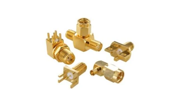
Various SMA connector designs showing different mounting structures and interface configurations. Proper SMA connector selection helps maintain stable RF signal transmission, impedance matching, and reliable cable assembly performance.
Check the RF interface before checking the supplier catalog
Many purchasing requests start with a simple description:
“SMA connector needed.”
From a supplier perspective, this information is incomplete.
An SMA connector used for a test cable, an antenna cable, and an internal RF module connection may have completely different requirements.
The front mating interface may all be SMA, but the rear structure can vary significantly.
The mistake is assuming that the SMA interface defines the entire product.
It does not.
The RF performance depends on the complete connection path:
SMA interface + dielectric structure + cable + termination process + installation condition
A connector that works well at a short laboratory distance may behave differently when the cable is longer, bent repeatedly, or installed inside a crowded enclosure.
Why does SMA remain common in RF and microwave equipment?
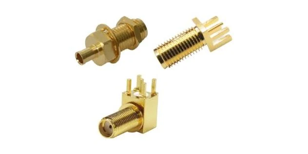
Examples of SMA PCB mount connector structures used in RF modules, wireless devices, evaluation boards, and embedded communication systems. The mounting footprint and grounding design affect overall RF performance.
This is a point that is often missed during purchasing.
A supplier may provide an SMA connector rated for a high frequency range, but the final cable assembly can still fail because:
- The cable attenuation is too high.
- The cable bend radius is exceeded.
- The connector termination is inconsistent.
- Multiple adapters introduce additional mismatch.
For RF assemblies, the connector rating is only one part of the evaluation.
Compare SMA with other RF connector interfaces before selecting
Different RF connectors exist because different applications have different mechanical and electrical requirements.
SMA is often selected when space is limited and a threaded RF connection is required. Other interfaces may be better suited for different environments.
| Connector | Main Characteristic | Common Application |
| SMA | Compact 50Ω threaded interface | RF modules, test cables, antenna connections |
| BNC | Quick locking connection | Laboratory instruments |
| N Type | Larger and more rugged structure | Outdoor antenna systems |
| TNC | Threaded version of BNC | Communication equipment |
| 2.92mm | Higher-frequency precision interface | Microwave measurement |
| Termination | Crimp / solder |
The selection should follow the actual application.
For example, replacing an SMA interface with an N Type connector is not simply an upgrade. The larger body may not fit the equipment structure. Similarly, replacing a precision microwave connector with a general-purpose SMA may affect measurement accuracy.
How Do SMA Male, Female, and Other Variants Differ?
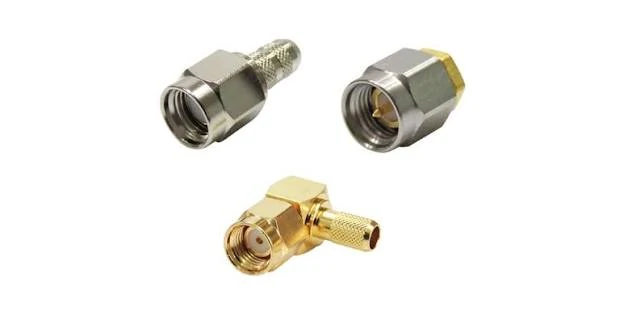
Comparison of SMA connector variants including male, female, and RP-SMA interfaces. Confirming connector polarity and gender before ordering helps prevent incorrect RF assembly selection.
Confirm SMA gender before creating the BOM
One of the simplest mistakes in RF procurement is also one of the most common:
Ordering the correct connector family with the wrong interface.
SMA male and SMA female connectors are mechanically different.
The difference is not only visible from the outside.
The center contact geometry determines how the two sides mate electrically. Incorrect selection may result in:
- Unable to connect
- Damaged contacts
- Loose mechanical engagement
- Unstable RF performance
For a production BOM, “SMA connector” is usually not enough information.
This type of information reduces unnecessary supplier clarification and prevents incorrect substitutions.
Why are RP-SMA connectors common in wireless products?
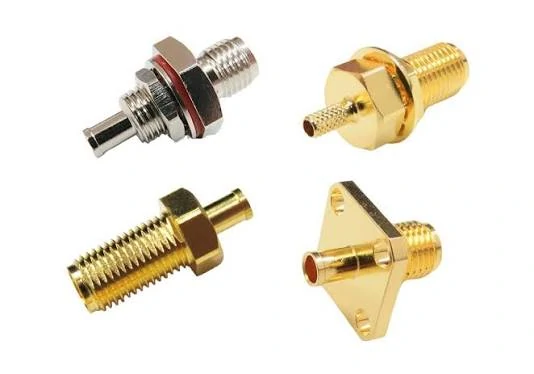
Different SMA mounting configurations designed for various RF installation requirements. Selecting the correct mounting style improves mechanical stability and simplifies integration into RF equipment.
RP-SMA appears frequently in WiFi and wireless networking products.
The external appearance is similar to standard SMA, but the center contact arrangement is reversed.
This creates an important sourcing point:
Standard SMA and RP-SMA should not be treated as interchangeable parts.
Typical applications include:
- WiFi routers
- Wireless access points
- Wireless communication products
A connector that looks similar may not work with the intended antenna or cable assembly.
For wireless products, confirming polarity before ordering avoids unnecessary rework.
How Should You Select the Right SMA Mounting Style?
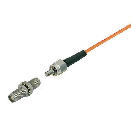
SMA coaxial cable assembly showing connector and cable integration. Matching the SMA connector with the correct coaxial cable type, impedance, and frequency range is important for stable RF performance.
A connector can meet the RF requirement and still fail during installation.
This happens when the mechanical structure is ignored during the early selection stage. For example, a cable-mounted SMA connector may work well in a flexible RF cable assembly, but it is not the right choice for a PCB where the connector needs to maintain a fixed position and controlled grounding.
The mounting method affects more than assembly convenience.
A cable assembly supplier usually needs to confirm:
| Item | Why It Matters |
| Cable type | Determines connector body and pin structure |
| Cable diameter | Affects ferrule and clamping method |
| Shield structure | Influences RF grounding |
| Termination method | Affects consistency and pull strength |
| Operating frequency | Determines usable RF range |
For production orders, the cable model should always be included in the BOM.
Writing only:
“SMA cable”
does not provide enough information.
A more useful specification would be:
“SMA male straight connector, 50Ω, for RG316 cable, crimp termination, DC–6GHz application.”
This reduces incorrect substitutions and improves supplier communication.
Select PCB mount SMA connectors for board integration
PCB mount SMA connectors are used when the RF interface needs to connect directly to a circuit board.
Common applications:
- Wireless modules
- RF evaluation boards
- Test fixtures
- Embedded antenna systems
The selection is usually related to:
- PCB thickness
- Mounting footprint
- Ground pad design
- Connector height
- Direction of cable connection
A PCB-mounted SMA connector creates an electrical transition from the transmission line on the PCB to the external RF cable.
This transition area requires careful layout.
A connector that is mechanically installed correctly may still show poor RF results if:
- The PCB ground connection is insufficient
- The signal trace is not matched
- The footprint differs from the recommended design
- The connector is mechanically stressed after assembly
For high-frequency designs, the PCB layout around the SMA connector is part of the RF structure.
Use bulkhead SMA connectors when external access is required
Bulkhead SMA connectors are selected when the RF connection needs to pass through an enclosure wall.
Typical examples:
- Communication equipment
- Outdoor antenna boxes
- RF measurement fixtures
- Industrial wireless devices
Compared with cable mount versions, bulkhead connectors add a fixed mounting function.
However, buyers should confirm more than the connector interface.
Important details include:
- Panel mounting hole size
- Thread length
- Nut and washer arrangement
- Waterproof requirement
- Cable exit direction
In outdoor applications, the connector mounting area can become part of the environmental protection design.
A mechanically loose bulkhead connector may create both installation problems and long-term reliability issues.
Use right-angle SMA connectors when space is limited
Right-angle SMA connectors are often selected for compact equipment where cable bending space is restricted.
They are useful in:
- Small RF modules
- Compact wireless devices
- Test fixtures with limited clearance
The advantage is simple:
The cable exits sideways instead of extending directly from the connector.
However, right-angle structures introduce another factor: the internal RF transition.
At higher frequencies, connector geometry becomes increasingly sensitive.
For applications near the upper frequency limit, testing the actual assembly is recommended instead of relying only on the connector specification.
How Do SMA Connectors Match RF Cables and Assemblies?
The connector is only one part of the RF path.
A common mistake in sourcing is selecting the cable first and adding a connector afterward. In practice, the connector and cable should be considered as a matched assembly.
An SMA connector must match:
- Cable diameter
- Impedance
- Frequency requirement
- Termination method
- Mechanical environment
The wrong combination may create issues that are difficult to identify during basic inspection.
The selection should consider:
- Operating frequency
- Cable length
- Required signal level
- Installation space
- Flexibility requirement
A shorter cable with a smaller diameter may be acceptable for an internal module connection. A longer cable used for testing may require lower attenuation.
The connector frequency rating cannot compensate for a cable that becomes the limiting factor.
Match SMA connectors with cable assemblies before ordering
A complete SMA cable assembly specification should include:
| Parameter | Example Requirement |
| Connector Type | SMA Male / SMA Female |
| Cable Type | RG316 / RG178 / Low Loss Cable |
| Impedance | 50Ω |
| Length | 300mm / 1m / Custom |
| Frequency Range | DC–6GHz / DC–18GHz |
| Termination | Crimp / Solder |
| Test Requirement | VSWR / Insertion Loss |
This information is especially important for OEM and ODM projects.
A supplier may be able to manufacture the connector, but the final RF result depends on whether the whole assembly is correctly defined.
Use coax antenna cables according to application requirements
SMA antenna cables are common in:
- WiFi equipment
- GPS devices
- IoT products
- Wireless communication systems
For antenna applications, the cable choice directly affects signal efficiency.
The interface alone does not define the correct assembly.
SMA Cable Matching Checklist
Before releasing an SMA cable assembly order, engineers and buyers can use the following checklist.
| Parameter | Check Requirement |
| Connector Interface | SMA male/female confirmed |
| Mounting Style | Cable mount, PCB mount, or bulkhead confirmed |
| Cable Type | RG316, RG178, low-loss cable, etc. |
| Impedance | 50Ω system |
| Frequency | Must match application band |
| Length | Confirm actual installation dimension |
| Termination | Crimp/solder process defined |
| Testing | VSWR or insertion loss requirement confirmed |
This checklist is useful because many RF failures are not caused by a defective connector. They happen because the connector, cable, and application requirements were not specified together
How Does Frequency Range Change SMA Connector Selection?
A 6 GHz SMA connector and an 18 GHz SMA connector may share the same external interface, but they are not always interchangeable in an RF system.
This difference is easy to miss during purchasing.
A drawing may only show “SMA connector” because the mechanical interface is standardized. However, once the frequency increases, the details inside the connector become more sensitive. The contact structure, dielectric support, machining accuracy, and cable transition all begin to influence the measured result.
For a low-frequency connection, a small variation may not be visible.
For a microwave test cable, the same variation can appear as:
- Higher VSWR
- Increased insertion loss
- Poor repeatability between batches
- Different measurement results after replacing the cable
The connector should be selected according to the working frequency of the complete RF path, not only according to the mating interface.
Check the operating band before selecting SMA frequency rating
A common question from buyers is:
“Can this SMA connector work at my frequency?”
The answer depends on the application.
A connector used at 3 GHz in a wireless module has different requirements from a connector used in a VNA test cable at 18 GHz.
Typical considerations:
| Application | Main Concern | SMA Selection Direction |
| Wireless module | Space and stable connection | Standard SMA |
| Antenna cable | Cable loss and installation | Matched SMA assembly |
| RF test cable | Repeatability and VSWR | Precision SMA |
| Microwave equipment | Higher frequency accuracy | High-frequency SMA |
The frequency value printed on a specification sheet should be treated as a reference point, not the only selection factor.
The cable often becomes the limiting part before the connector.
For instance, an SMA connector may support a higher frequency range, but a long cable assembly with unsuitable coaxial cable can still create excessive loss.
Leave frequency margin instead of selecting exactly at the limit
In engineering projects, selecting a connector exactly at the operating frequency can create unnecessary risk.
A simple evaluation method is:
Frequency Margin Ratio = Connector Rated Frequency ÷ System Operating Frequency
Example:
System frequency: 8 GHz
Connector rating: 18 GHz
Frequency Margin Ratio:
18 ÷ 8 = 2.25
A practical reference:
| Ratio | Application Consideration |
| Around 1.2× | Basic RF connection |
| Around 1.5× | General test and communication use |
| Above 2× | Sensitive measurement or demanding RF paths |
The margin does not guarantee better performance.
It provides more tolerance for:
- Production variation
- Cable replacement
- Connector aging
- Assembly differences
Which RF Tests Should Be Included Before SMA Assembly Approval?
A connector can look perfect under visual inspection and still fail during RF measurement.
This is especially common in cable assemblies.
The reason is that RF performance depends on the entire transition.
Inspect mechanical details before electrical testing
Before connecting equipment such as a VNA, basic inspection should confirm:
- Thread condition
- Contact alignment
- Housing condition
- Cable termination appearance
- Strain relief condition
These checks help identify obvious assembly problems.
However, they cannot replace RF testing.
A continuity test only confirms that the electrical path is connected.
It does not show whether the impedance is controlled.
Verify VSWR and insertion loss according to the application
For RF applications, the commonly checked parameters include:
VSWR
VSWR indicates how well the RF signal path is matched.
A higher-than-expected value may come from:
- Incorrect connector installation
- Damaged center contact
- Poor cable termination
- Excessive cable bending
- Connector contamination
The connector is only one possible cause.
Insertion Loss
Insertion loss shows how much signal power is reduced through the assembly.
Factors affecting loss include:
- Cable material
- Cable length
- Connector quantity
- Frequency
- Termination quality
A short SMA cable used inside equipment may tolerate a different loss level compared with a 2-meter test cable.
The acceptance requirement should match the actual application.
Why Should SMA Replacement Parts Be Checked Before Substitution?
Replacement projects often create unexpected problems.
A customer may provide:
“Replace this SMA connector with the same one.”
At first glance, the request looks simple.
But the original part may include hidden details:
- Special cable compatibility
- Different plating
- Different termination method
- Different mounting structure
- Different frequency requirement
Two SMA connectors can mate together and still not be equivalent.
Before approving a replacement, compare:
| Check Item | Confirm |
| Interface | SMA male/female |
| Cable compatibility | Same cable model |
| Impedance | 50Ω |
| Frequency range | Suitable margin |
| Mounting | Same mechanical structure |
| Termination | Same production method |
This is especially important for products already in mass production.
A connector change that works on one sample may create consistency problems later.
What Information Should Be Included in an SMA RF Request?
Many RF inquiries start with limited information:
“Need SMA cable, 100 pcs.”
For standard products, this may be enough for an initial discussion.
For custom assemblies, it is not.
A supplier usually needs:
- Connector interface
- Gender
- Cable type
- Length
- Frequency range
- Application
- Quantity
- Test requirement
A clearer RF request looks like this:
| Item | Example |
| Connector | SMA Male |
| Mounting | Straight Cable Mount |
| Cable | RG316 |
| Impedance | 50Ω |
| Length | 500mm |
| Frequency | DC–6GHz |
| Application | Antenna connection |
| Inspection | VSWR check |
This information helps determine whether a standard SMA assembly is suitable or whether a customized structure is needed.
SMA Connector Acceptance Checklist for Production Use
Before shipment approval, the inspection method should match the application requirement.
A practical checklist:
| Inspection Point | Requirement |
| Interface | Correct SMA standard |
| Gender | Confirm matching |
| Thread | Smooth mating |
| Contact | No deformation |
| Cable | Correct model and length |
| Impedance | 50Ω system |
| Frequency | Suitable for application |
| VSWR | Test when required |
| Appearance | No visible defects |
For general-purpose RF connections, appearance and mechanical checks may be sufficient.
For test equipment, microwave systems, or sensitive RF links, electrical measurement should be included.
FAQ
Can an SMA connector rated at 6 GHz be used in a 5.8 GHz system?
It may work, but the complete assembly should still be reviewed. Cable type, connector tolerance, termination quality, and required VSWR performance all affect the final result.
Can SMA and RP-SMA connectors replace each other?
No. They have different contact arrangements. The external appearance can be misleading, so polarity must be confirmed before replacement.
Does a higher-frequency SMA connector always provide better performance?
No. A higher frequency rating only indicates the connector capability. Cable selection, assembly quality, and installation condition still determine the actual RF result.
Should I select an SMA connector only based on the required frequency?
Frequency is an important factor, but it is not the only one. The cable type, cable length, number of adapters, and expected test condition also affect the final RF performance. For example, an SMA connector used for a short internal connection may have different requirements from one used for a microwave test cable. The complete assembly specification should be reviewed before selection.
Can two SMA connectors with the same thread size be used as replacements?
Not necessarily. The SMA interface may be the same, but the rear structure can be different. The cable diameter, pin size, mounting method, and termination process all need to match the original assembly. A replacement connector may fit mechanically and still create different RF results after assembly. For production use, it is better to confirm the cable model and original specification before changing the connector.
