
A customer once received an SMA cable assembly that looked correct on the drawing.
The connector type matched.
The cable length was within tolerance.
The continuity test passed.
But after the cable was installed into the equipment, the RF test result changed.
The problem was not the SMA interface itself. The cable had been routed differently from the sample condition, and the bending position introduced a mismatch that was not visible during the first inspection.
This situation is common in RF cable sourcing. A cable that works on a workbench does not always behave the same way inside a finished product.
For an sma connector cable, the connector, coaxial cable, termination process, and installation method form one complete RF path. Checking only the connector model is usually not enough.
Engineers and buyers normally need to confirm several details before production:
- SMA interface type and gender
- Cable structure and diameter
- Operating frequency
- Cable length
- Impedance requirement
- Assembly method
- RF test requirements
A small mistake in any one of these items can create problems later during assembly, testing, or mass production.
How Do SMA Connector Cables Fit Into Real RF Systems?
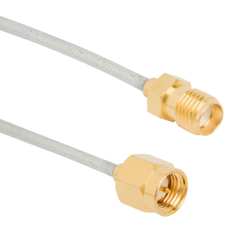
A separately purchased SMA connector may have acceptable specifications, but the final result still depends on:
- How the cable is stripped
- How the center conductor is positioned
- How the shield is connected
- Whether the crimping force is stable
- Whether the finished cable passes RF inspection
This is also why two cables using the same SMA connector may not perform identically.
The front interface only defines the connection method. The actual RF behavior depends on the complete assembly.
Why Do Buyers Often Choose SMA Cable Assemblies Instead of Loose Parts?
A finished sma cable assembly usually provides better production consistency because the cable length, connector termination, and inspection method are controlled before shipment.
A more useful RF purchasing description would include:
| Specification Item | Example Requirement |
| Connector A | SMA Male |
| Connector B | SMA Female |
| Cable Type | RG316 |
| Impedance | 50Ω |
| Length | 300 mm |
| Frequency Range | DC-6 GHz |
| Application | RF module / antenna / test |
The missing details in a simple request are often where problems start.
For example, RG316 and RG58 can both be used with SMA connectors, but they are not interchangeable. Their cable diameter, flexibility, attenuation, and termination structure are different.
A connector supplier who does not check the cable compatibility may provide a mechanically matched product that is unsuitable for the actual application.
Comparing SMA Connector Cable With Other RF Cable Options
Different cable products solve different problems. A flexible internal connection, a laboratory test cable, and an outdoor antenna connection may all use SMA interfaces, but the cable requirements are different.
| Cable Solution | Common Use | Main Consideration |
| SMA Connector Cable | General RF connection | Interface matching |
| SMA Extension Cable | Equipment distance adjustment | Additional cable loss |
| SMA Cable Assembly | OEM production | Manufacturing consistency |
| Custom RF Cable | Special projects | Connector and routing requirements |
In many RF projects, the connector selection is decided first because it is visible on the equipment drawing.
The cable selection deserves the same attention.
At higher frequencies, the cable can become the limiting factor before the connector reaches its rated frequency. A low-cost cable choice may increase attenuation or create unexpected measurement differences.
How Do You Match SMA Cable Ends With Equipment Interfaces?
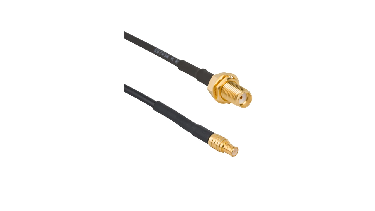
This SMA connector cable features a panel mount SMA female connector and compact coaxial cable structure, providing a reliable RF connection solution for antennas, wireless modules, and electronic equipment.
One of the easiest mistakes to make during purchasing is selecting the correct connector family but the wrong interface combination.
SMA male and SMA female connectors are not interchangeable.
Before ordering an SMA cable, the engineer should check the actual equipment interface, not only the product photo.
Important information includes:
- Connector gender
- Thread interface
- Installation direction
- Space around the port
- Required cable exit angle
A common example is replacing an existing antenna cable.
The replacement cable may have the same SMA name, but if the original assembly used a right-angle connector and the replacement uses a straight connector, the cable may not fit the enclosure.
When Should You Use SMA Male Cable or SMA Female Cable?
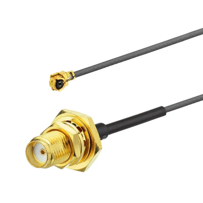
An sma male cable is generally used to connect with equipment ports that provide an SMA female interface.
The center contact is a pin, and the threaded outer connection provides mechanical fixing.
An sma female cable uses a socket contact and connects with an SMA male interface.
The selection itself is simple. The difficulty usually appears when the cable is part of a larger system.
For example:
- Antenna side may require SMA male
- Module side may require SMA female or board connector transition
- Test equipment may require a different adapter combination
A wrong gender selection may stop the mechanical connection completely, while a wrong cable type may only appear after RF testing.
| SMA Configuration | Typical Application |
| SMA Male to SMA Female | Equipment connection extension |
| SMA Male to SMA Male | RF device connection |
| SMA Female to SMA Female | Interface conversion |
| Right-angle SMA | Compact installation space |
| Custom SMA Combination | OEM equipment |
Why Does Connector Angle Matter During Installation?
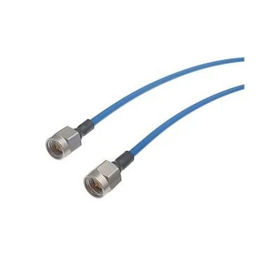
Flexible SMA coaxial cable assembly helps connect RF components in compact systems where cable routing space and installation flexibility are important.
The connector shape affects more than convenience.
A straight SMA connector is suitable when there is enough space behind the equipment port.
A right-angle SMA connector is often selected for compact devices because it reduces the space required behind the interface.
However, the design decision should consider the cable itself.
A tight bend near the connector can create:
- Mechanical stress
- Shield deformation
- Long-term reliability issues
- Possible RF variation
During sample evaluation, the cable is often placed carefully on the test bench. During actual production, workers may route hundreds of cables through limited spaces. That difference is where many assembly issues appear.
How Do Cable Materials Change SMA Connector Cable Performance?
A connector can be correct and the cable can still be the wrong choice.
This is something that appears frequently during RF cable replacement projects.
A customer may send a drawing that only shows:
- SMA connector type
- Cable length
- Quantity
The missing information is usually the cable model.
For low-frequency connections, this may not create an immediate problem. But once the frequency increases or the cable becomes longer, the coaxial cable starts to influence the result.
The cable inside an sma connector cable determines several practical factors:
- Signal attenuation
- Minimum bend radius
- Mechanical strength
- Installation difficulty
- Temperature suitability
- Final assembly size
A supplier selecting the cable only by connector interface may deliver a product that can be installed but does not match the RF requirement.
Why Is RG316 Commonly Used With SMA Connector Cables?
RG316 is widely used in SMA cable assemblies because it fits many general RF connection requirements.
It is often selected for:
- Internal equipment wiring
- RF module connections
- Short antenna connections
- Test fixture wiring
One reason is its flexibility.
Inside compact equipment, the cable often needs to pass around batteries, PCBs, shielding plates, or mechanical supports. A stiff cable can transfer force directly to the SMA connector after installation.
However, RG316 is not suitable for every distance.
A short cable between two nearby RF points may work well. The same cable extended several meters may introduce more loss than expected.
This is why cable length and cable type should always be considered together.
The second description leaves the supplier to decide the most important part of the assembly.
Where Does RG178 Fit Compared With RG316?
RG178 is often selected when equipment size becomes the limiting factor.
Some RF products simply do not have enough space for a standard coaxial cable.
Examples include:
- Small GPS equipment
- Embedded wireless modules
- Compact IoT devices
- Portable RF instruments
The smaller diameter helps routing inside tight structures.
But smaller size also changes the design balance.
A thinner cable may provide easier installation while requiring more attention to:
- Pull force during assembly
- Connector termination method
- Cable bending
- Required RF distance
For production buyers, the question is usually not:
“Which cable is better?”
The more useful question is:
“Which cable creates fewer problems in the final equipment?”
A compact device may benefit from RG178. A test system requiring longer cable distance may need a different coaxial structure.
When Should a Low Loss RF Cable Replace Standard Coaxial Cable?
Longer RF paths create a different problem.
The connector may still be SMA. The impedance may still be 50Ω. But the cable loss gradually reduces the available signal level.
This appears in applications such as:
- Remote antenna systems
- Outdoor wireless equipment
- RF measurement setups
- Communication equipment with separated modules
For these applications, engineers often consider low loss RF cables.
The decision normally depends on:
- Operating frequency
- Cable length
- Allowable insertion loss
- Mechanical installation
A low loss cable can reduce attenuation, but it may also introduce different mechanical characteristics.
Some low loss cables are larger in diameter and less flexible. If the equipment requires repeated movement or tight routing, the cable structure needs additional evaluation.
SMA Cable Material Comparison for RF Design
The following table can be used during early cable selection.
| Cable Type | Usually Selected For | Main Trade-off |
| RG316 | General RF connection, internal wiring | Higher loss on longer runs |
| RG178 | Compact equipment | Smaller size with different mechanical limits |
| Mini Coax | Space-limited modules | Requires careful termination |
| Low Loss Coax | Longer RF paths | Larger size or reduced flexibility |
The cable choice should be recorded in the product specification or BOM.
A common production issue happens when purchasing replaces a cable with a “similar” one because the connector is unchanged.
The replacement may physically fit.
The RF result may not.
How Does Cable Length Affect SMA RF Results?
Cable length is often treated as a simple mechanical dimension.
In RF systems, it is an electrical parameter as well.
A 100 mm cable and a 1 m cable using the same SMA connector are not equivalent.
The longer cable introduces additional attenuation.
This value only represents cable loss.
Why Should Connector Count Be Included in RF Loss Calculation?
During system design, engineers sometimes calculate only the cable.
The actual signal path may contain several connection points.
A typical measurement setup may include:
RF equipment → adapter → SMA cable → adapter → device
Every additional interface can introduce:
- Insertion loss
- Reflection
- Mechanical tolerance variation
This calculation does not replace measurement, but it helps identify possible risk before hardware testing.
SMA Cable Loss Record Example
For engineering communication, a simple record is often enough:
| Item | Example Value |
| Cable Model | RG316 |
| Length | 500 mm |
| Frequency | 6 GHz |
| Attenuation | Confirm from cable datasheet |
| Connector Quantity | 2 |
| Adapter Quantity | 0 |
| Test Requirement | VSWR / Insertion Loss |
This type of information prevents different departments from interpreting “SMA cable” differently.
Engineering may understand it as an RF component.
Purchasing may understand it as a connector with a wire.
Those are not the same specification.
What Should Be Confirmed Before Approving an SMA Cable Assembly?
Before mass production, the supplier and buyer should confirm the same information.
A basic RF cable specification should include:
| Specification | Required Information |
| Connector Interface | SMA male / female |
| Cable Type | RG316 / RG178 / Low Loss |
| Impedance | 50Ω |
| Length | Tolerance included |
| Frequency | Operating range |
| Test Method | VSWR / Insertion Loss |
| Quantity | Sample or production batch |
This information reduces the risk of receiving a cable that matches the drawing but fails in the equipment.
Where SMA Connector Cables Are Used in Real Wireless Designs
A cable drawing usually looks simple.
One connector on each side.
A defined length.
A cable number in the BOM.
The trouble often starts after the prototype moves into a finished product.
The antenna position changes. The enclosure becomes smaller. The RF port needs to move to another location. Suddenly the cable that worked during testing needs to be redesigned.
This is one reason SMA connector cables remain common in wireless equipment.
They provide a practical way to connect RF modules, antennas, and external interfaces without changing the complete mechanical structure.
Typical uses include:
- WiFi equipment
- GPS receivers
- Cellular communication products
- IoT gateways
- RF evaluation boards
- Antenna test systems
The cable is not only carrying the signal. It is also solving a mechanical layout problem.
Cable Routing Can Change the Final RF Result
During early development, engineers usually test the cable in an open environment.
The cable is straight.
The connector is easy to access.
Nothing is pressing against the assembly.
The production unit is different.
The same cable may need to pass around:
- Shielding covers
- Batteries
- PCB edges
- Mechanical brackets
- Other cables
A cable that is forced into a small bending radius may transfer stress to the connector termination area.
This is especially important for small wireless devices where every millimeter of space matters.
When reviewing an SMA antenna cable design, engineers usually check:
- Cable diameter
- Connector orientation
- Minimum bend radius
- Mounting position
- Service access after assembly
The shortest cable is not always the correct cable.
A few extra millimeters may make assembly easier and reduce mechanical stress.
Using U.FL to SMA Cable for Compact RF Modules
Many wireless modules do not provide a panel-mounted RF connector directly.
Instead, the PCB may use a miniature connector.
A common example is a U.FL interface.
A U.FL to SMA cable creates a transition between the small PCB connector and a standard SMA port.
This configuration appears in:
- Development boards
- WiFi modules
- GPS modules
- Cellular communication boards
The selection process requires more attention than simply checking the connector name.
A buyer should confirm:
- The exact miniature connector type
- SMA gender
- Cable diameter
- Cable length
- Frequency requirement
One common mistake is replacing a U.FL cable with a visually similar part.
The connector may look correct in a product photo, but the mating structure may be different.
For prototype testing, this mistake may only waste time.
For production, it can create assembly failures.
SMA Cable Assembly Becomes More Important During Production
A prototype only proves that one design can work.
Mass production introduces another requirement:
Repeatability.
For OEM projects, the question changes from:
“Can this cable work?”
to:
“Can every cable work the same way?”
This is where an SMA cable assembly with defined specifications becomes useful.
A production requirement normally includes more than the connector name.
For example:
| Specification | Example Requirement |
| Connector 1 | SMA Male |
| Connector 2 | SMA Female |
| Cable | RG316 |
| Length | 300 mm |
| Impedance | 50Ω |
| Frequency | DC-6 GHz |
| Inspection | VSWR check |
This information gives the supplier a clear production target.
Without these details, different suppliers may interpret “SMA cable” differently.
One supplier may select RG316.
Another may choose a different coaxial cable.
Both products may look similar from the outside.
The difference appears during installation or RF testing.
What Should Be Checked Before Accepting an SMA Cable Shipment?
A cable passing continuity inspection does not automatically mean the assembly is ready for RF use.
Continuity testing answers one question:
“Is the electrical path connected?”
RF testing answers different questions:
“Does the transmission path behave correctly?”
For SMA cable assemblies, acceptance usually involves both mechanical and electrical inspection.
Mechanical Inspection Before RF Testing
The basic inspection items include:
| Check Item | Reason |
| Connector model | Confirm correct interface |
| Gender | Avoid mating problems |
| Cable length | Match drawing requirement |
| Cable appearance | Check assembly condition |
| Connector position | Confirm installation |
| Label information | Maintain traceability |
These checks appear simple, but they prevent many production issues.
A wrong connector gender can stop assembly immediately.
A wrong cable length may create routing problems inside the equipment.
FAQ
Can I replace an SMA cable with another brand directly?
Only after checking the complete specification. The connector interface may match, but cable structure, length, and termination quality can affect the final result.
What should I tell a supplier before ordering an SMA cable assembly?
The connector type alone is usually not enough.
A supplier will normally need the SMA interface on both ends, cable type, cable length, frequency range, impedance, quantity, and any testing requirements.
Can I replace a U.FL to SMA cable with another similar-looking cable?
It is better to check the exact connector model first.
Small RF connectors can look very similar, but the mating structure may be different. A cable that fits physically may not be the correct replacement.
My SMA cable passes continuity testing. Do I still need RF testing?
For basic connections, continuity testing may be enough.
For RF applications, it does not show the complete cable performance. VSWR and insertion loss testing can help find problems that cannot be seen from a normal electrical check.
