
The antenna worked on the bench. After the radio was installed inside a metal cabinet, the link became unstable.
The first response is often to fit a higher-gain antenna. That may not solve the real problem. If the enclosure, machinery, vehicle body, battery pack, or mounting surface is blocking the RF path, moving the existing antenna can produce a larger improvement than replacing it.
An SMA antenna extension cable makes that relocation possible. The cable does not amplify the signal. It introduces insertion loss and another pair of RF transitions. Its value comes from placing the antenna where it has a clearer path, less shielding, or better sky visibility.
A useful extension therefore cannot be selected by length alone. Buyers must match the device port, antenna connector, cable construction, operating frequency, installation route, environmental exposure, and finished-assembly test limits.
Which Antenna Relocation Problem Is the Cable Solving?
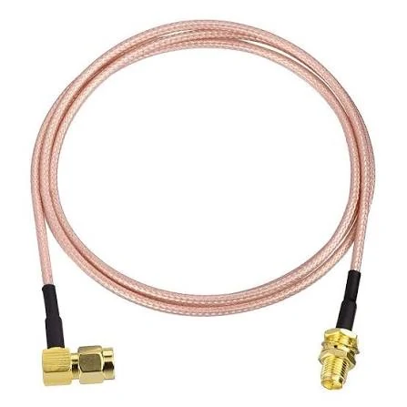
SMA antenna extension cable featuring a right-angle connector and a female bulkhead-style interface. This configuration is useful for compact RF installations where axial clearance is limited or the antenna connection needs to pass through a panel.
Start with the obstruction, not the cable part number.
Common relocation cases include a wireless gateway inside a rack, a cellular modem behind machinery, a GNSS receiver below a metal roof, or a vehicle radio installed under the dashboard. In each case, the radio may be functioning correctly while the antenna sits in a poor RF position.
A standard male-to-female assembly often preserves the existing antenna interface:
Device SMA Female Port→ SMA Male Cable End→ 50 Ω Coax→ SMA Female Cable End→ Existing SMA Male Antenna This arrangement allows the original removable antenna to remain in use. It also avoids changing the device connector or adding multiple rigid adapters.
A cable is justified when the new antenna position delivers more link improvement than the extension removes. Moving an antenna from inside a grounded metal enclosure to an external panel may produce a strong benefit. Moving it 30 cm within the same unobstructed room may only add loss.
| Existing problem | Proposed antenna position | Likely benefit | Main risk | Action |
| Antenna inside metal cabinet | Outside panel | High | Panel and cable loss | Extend |
| GNSS antenna below metal roof | Clear roof position | High | Route and sealing | Extend |
| Antenna already has clear line of sight | Similar nearby position | Low | Added insertion loss | Keep original |
| Cellular antenna beside a noise source | Separated position | Medium | Band-dependent loss | Test |
| Long cable with no location improvement | Same RF environment | Low | Loss dominates | Redesign |
The cable should solve a visible installation problem. It should not be added because a longer cable appears more convenient.
Will the Device Port and Antenna End Mate Correctly?
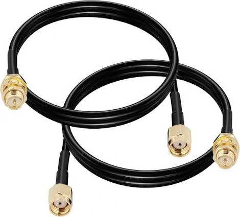
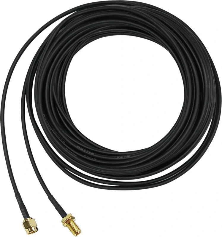
Black SMA male-to-female antenna extension cable assemblies for relocating an RF antenna away from a radio, modem, enclosure, or other obstructed mounting position. Connector polarity, cable length, operating frequency, and insertion loss should be confirmed before installation.
“SMA” is not enough information for an order.
Standard SMA and reverse-polarity SMA use similar threaded bodies, but their center contacts differ. The thread and center contact must both be checked.
| Interface | Thread | Center contact |
| SMA male | External | Pin |
| SMA female | Internal | Socket |
| RP-SMA male | External | Socket |
| RP-SMA female | Internal | Pin |
IEC 61169-15:2021 covers the specification framework for threaded, 50-ohm Type SMA RF coaxial connectors.
A thread-only inspection can therefore approve the wrong part. Certain mismatched connectors may begin to screw together while the center contacts fail to make a proper electrical connection. Another failure mode is contact damage: a pin is pushed against another pin, or an unsupported contact becomes deformed during repeated attempts.
Inspect each end separately:
- Device interface and center contact
- Antenna interface and center contact
- Standard SMA or RP-SMA
- Straight or right-angle body
- Inline or panel-mount construction
- Available mating and wrench clearance
For a device with an SMA female port and an existing SMA male antenna, the usual extension is an SMA male to female extension cable. That arrangement preserves the original connection path without a gender adapter.
Routers require extra care. Many consumer Wi-Fi products use RP-SMA rather than standard SMA. The RP-SMA vs SMA identification guide provides a visual method for checking the thread and center contact before a cable is ordered.
Which Coax Construction Fits the Required Run?
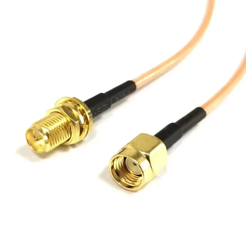
RG316 is a practical option for short antenna extensions because it combines a small diameter, flexible routing, 50-ohm construction, and temperature-resistant dielectric materials. It fits compact gateways, vehicle equipment, embedded radios, and short panel transitions.
That does not make it a universal antenna feeder.
An RG316 antenna cable becomes less attractive as distance and frequency increase. Its miniature construction saves space, but the smaller conductor and cable dimensions produce more attenuation than larger low-loss cable families.
The selection should follow the physical route:
| Requirement | RG174 or RF1.13 | RG316 | RG58 or low-loss coax |
| Very small enclosure | Strong fit | Good fit | Usually difficult |
| Short flexible extension | Suitable | Preferred | Optional |
| Several-meter route | Review carefully | Calculate loss | Usually better |
| Elevated temperature | SKU-dependent | Strong option | Verify construction |
| Minimum attenuation | Weak | Moderate | Stronger |
| Tight routing | Strong | Strong | More space required |
| Outdoor fixed feed | Limited | Review | Better starting point |
RG174 or RF1.13 may be useful for very short internal leads where space is the dominant constraint. However, buyers should not assume they are direct substitutes for RG316. Shielding, jacket material, temperature rating, attenuation, connector termination, and flex life can all change.
RG58 and larger low-loss families deserve consideration when the cable is several meters long, when the system operates near 5 GHz or above, or when receive margin is limited. The enclosure may need a larger bend space and a larger connector rear body, but the electrical improvement can justify that mechanical cost.
The RG316 cable selection guide provides a broader comparison of RG316 routing, attenuation, termination, and sourcing limits.
How Far Can the Antenna Move Before Cable Loss Wins?
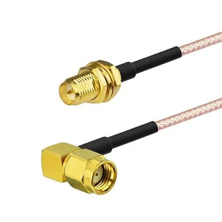
Close-up of an SMA extension cable with a right-angle male connector and female bulkhead connector. This cable geometry is suitable for RF equipment, wireless gateways, antennas, vehicle radios, and other installations with restricted connector clearance.
Cable length must be calculated at the real operating frequency.
Where:
- is cable attenuation at the target frequency in dB per meter.
- is the selected cable length in meters.
A 1 GHz attenuation value should not be used to approve a 5 GHz assembly. Attenuation rises with frequency, and the cable may become the limiting component before the SMA interface reaches its published frequency rating.
The complete RF-path estimate should include every transition:
Additional interfaces may include a bulkhead, right-angle adapter, lightning protector, panel feedthrough, gender adapter, or antenna combiner.
Consider a hypothetical project in which the approved cable data shows 1.1 dB/m at the highest operating frequency. A 3 m run would contribute approximately 3.3 dB before the connector and accessory allowance is added. If the project permits only 3 dB of additional path loss, that build is already unsuitable even though the connectors fit.
Buyers can also calculate the maximum available length:
Use the cable manufacturer’s data or measured assembly data for α(f)\alpha(f)α(f). Do not copy a generic value from another RG316 product without checking conductor construction, shield coverage, and test conditions.
Which Length Fits Wi-Fi, GPS, 4G, or 5G?
Application labels are not electrical specifications.
“Wi-Fi compatible,” “GPS cable,” and “5G antenna extension cable” do not state the highest operating frequency, permitted insertion loss, connector standard, or cable construction.
GPS and GNSS
A GPS or GNSS installation should distinguish between active and passive antennas. An active antenna may carry DC bias through the center conductor, so the cable assembly must support both the RF signal and the required current.
The position improvement can be substantial when an antenna moves from beneath a metal roof to a clear sky-facing location. Still, the receiver noise budget, cable loss, lightning-protector loss, shielding, and bias voltage at the antenna should be reviewed.
2.4 GHz and 5 GHz Wi-Fi
A length accepted for 2.4 GHz should not automatically be approved for 5 GHz. The same cable normally has higher attenuation at the higher band.
For dual-band equipment, calculate loss at the highest required frequency. Also confirm whether the device uses standard SMA or RP-SMA. The Wi-Fi antenna extension cable guide covers the Wi-Fi-specific connector and routing questions in more detail.
4G and 5G cellular systems
A 4G antenna extension cable with SMA connectors must support the exact cellular bands used by the modem, not merely a broad “4G” label. The same applies to 5G equipment.
Record the lowest and highest required bands. For MIMO equipment, specify the number of assemblies and whether equal electrical lengths are required. One branch should not be casually substituted with a different cable type or length.
U.S. 6 GHz equipment
The U.S. 6 GHz unlicensed allocation extends from 5.925 to 7.125 GHz. A finished cable assembly qualified only through 6 GHz should therefore not be marketed as covering the complete U.S. 6 GHz band. The assembly must be evaluated to the equipment’s actual upper frequency.
Does the Route Need Straight, Right-Angle, or Bulkhead Ends?
Connector geometry affects both installation and reliability.
Straight ends are suitable when the device and antenna have sufficient axial clearance. They simplify assembly and usually avoid the orientation questions associated with right-angle connectors.
A right-angle end is useful when the radio sits close to an enclosure wall, under a shelf, or behind a dashboard. The right-angle connector should be placed on the constrained side rather than added later as a separate rigid adapter.
Compare these two paths:
Device→ Right-Angle Adapter→ Straight SMA Extension→ Antenna Device→ Right-Angle SMA Extension→ Antenna The purpose-built cable removes one detachable interface and one possible loosening point.
Right-angle specifications should identify the cable exit direction and, where orientation matters, the connector clocking. “Right angle” alone may still leave the cable pointing toward the wrong side of the enclosure.
A bulkhead end is more suitable when the cable must pass through a panel or when the enclosure should carry the external antenna load. Repeated antenna replacement should load the panel hardware, not a PCB-mounted RF connector inside the device.
Panel designs must state the mounting-hole diameter, panel thickness, available thread length, washer arrangement, grounding requirement, and sealing method.
How Should Indoor, Vehicle, and Outdoor Builds Differ?
An indoor assembly usually prioritizes flexible routing, service access, identification, and avoiding unnecessary cable coils. It still needs strain relief and clearance from hot power components or sharp sheet-metal edges.
Vehicle installations add vibration, temperature cycling, cleaning chemicals, and movement during servicing. A cable hanging freely from the back of a radio can apply repeated leverage to the connector. Support the route and place the bulkhead or clamp where external movement will not reach the device port.
Outdoor requirements go beyond fitting an O-ring to an SMA connector. The finished installation may need:
- UV-resistant cable protection
- Corrosion-resistant panel hardware
- Sealed panel transition
- Weatherproof connector joint
- Drip loop
- Protected cable entry
- Water-blocking cable construction
- Defined replacement procedure
A standard indoor RG316 SMA extension cable should not be described as a permanent outdoor assembly merely because the installer can wrap tape around the connector.
Sealing should be separated into four requirements: electrical mating interface, panel seal, cable-entry seal, and external weatherproofing. Each has a different failure mechanism. Water can bypass a sealed connector face through the panel cutout or travel along the cable entry if only the mating thread is protected.
What Electrical Limits Must the Finished Assembly Meet?
The complete assembly—not only the bulk cable—should maintain a nominal 50-ohm RF path.
That includes:
- Device port
- SMA male connector
- Coaxial cable
- SMA female connector
- Antenna
- Any bulkhead, protector, or adapter
A cable can pass center-conductor continuity and still have poor RF performance. Excess braid disturbance, incorrect strip length, weak shield contact, solder wicking, center-pin displacement, or a loose crimp can create reflections that a multimeter will never detect.
A useful finished specification is measurable:
Avoid a purchasing description such as “SMA cable, 0–6 GHz.” It does not bind the frequency claim to the selected cable, length, connector termination, or test method.
| Parameter | RFQ requirement |
| Connector A | Standard SMA male |
| Connector B | Standard SMA female |
| Cable | RG316 or approved alternative |
| Impedance | 50 Ω |
| Length | Target and tolerance |
| Operating band | Lowest to highest frequency |
| Insertion loss | Maximum at stated frequency |
| VSWR or return loss | Limit across full band |
| RF power | Maximum input |
| DC bias | Voltage and current, if required |
| Inspection | Sample or 100% RF test |
Power and DC-bias requirements should be stated even when the assembly is mainly described as an antenna cable. A receive-only GNSS path, cellular transmit path, and laboratory RF jumper do not impose the same electrical stress.
How Can Length Variants Be Standardized Into Clear SKUs?
The connector identity should appear at the beginning of the product name:
SMA Male to Female RG316 Antenna Extension Cable
Each SKU should then carry the variables that affect fit and performance:
SMA-MF-RG316-ST-ST-0.3M SMA-MF-RG316-ST-ST-1M SMA-MF-RG316-ST-ST-3M SMA-MF-RG316-ST-ST-5M
A right-angle or bulkhead version should use a different code rather than sharing the same base SKU without explanation.
Length measurement also needs one fixed reference. Possible methods include connector reference plane to reference plane, tip to tip, jacket length only, or bulkhead face to the opposite connector plane. Mixing these methods can create a meaningful difference in a compact installation.
A 1 m, 3 m, and 5 m product should not share one unqualified RF claim. Each length variant should have its own expected insertion-loss limit, length tolerance, packaging label, and recommended operating range.
For longer assemblies, review whether an RG316 versus RG58 cable comparison should be completed before the SKU is released.
What Must the RFQ Include Before Production Starts?
A workable RFQ should allow a supplier to build the cable without interpreting product photos or informal connector names.
Use a block such as this:
The application should also be named. “General antenna cable” is not enough. State whether the assembly is for Wi-Fi, GNSS, cellular, an IoT gateway, vehicle radio, laboratory equipment, or another defined RF path.
The general SMA extension cable guide can be used when the project includes non-antenna extension applications as well.
How Can Incoming Inspection Catch the Wrong Assembly?
Inspect connector polarity before distributing the batch to production.
Confirm the thread, pin or socket, connector orientation, cable marking, overall length, and SKU label. A sample bag marked “SMA male to female” can still contain an RP-SMA end or the wrong bulkhead thread length.
Mechanical inspection should cover:
- Ferrule position
- Exposed braid
- Cable-jacket cuts
- Center-contact position
- Rotating connector bodies
- Heat-shrink condition
- Sharp bends at the connector exit
- Right-angle orientation
- Bulkhead dimensions
Electrical inspection should be matched to project risk. Continuity and center-to-shield isolation are reasonable for every assembly, but they do not replace RF testing.
A first-article VNA report is useful when a new cable, connector, length, or termination process is introduced. Batch sampling may be sufficient for stable commercial products. Critical measurement, aerospace, military, or low-margin receive paths may require 100% insertion-loss and return-loss testing.
The acceptance result should be tied to the drawing and RFQ, not to comparison with an unapproved sample.
When Should Another Cable Assembly Replace the SMA Extension?
RG316 is the wrong choice when its calculated loss exceeds the project budget, even if it is mechanically convenient.
Move to a lower-loss cable when:
- The route is several meters long
- The upper operating band dominates performance
- Receiver margin is limited
- Multiple accessories are already in the RF path
- A larger bend radius can be accommodated
- The route is fixed rather than frequently moved
A panel design may also benefit from a two-section architecture:
Internal RF Port→ Short Supported Pigtail→ Panel-Mount SMA Bulkhead→ External Antenna or Low-Loss Feeder This keeps the internal lead short and protects the PCB connector from external pulling or antenna replacement.
Use a right-angle cable when immediate axial bending would otherwise stress the connector. Use a rigid adapter only when no cable distance or mechanical isolation is required.
A practical architecture decision looks like this:
FAQ
Does moving an antenna farther from the radio always improve reception?
No. The extension adds cable and connector loss. Relocation helps only when the new position provides a meaningful RF advantage, such as clearer line of sight, reduced metal shielding, greater separation from interference, or better sky visibility. Compare signal quality before and after relocation whenever practical. A longer route to a nearly identical antenna position usually reduces rather than improves the available link margin.
Can one SMA antenna extension be used for GPS and cellular equipment?
Only when the assembly meets both applications’ requirements. Check impedance, interface polarity, frequency range, insertion loss, RF power, shielding, and environmental limits. An active GPS antenna may also require DC bias through the cable. A cable qualified for a low-power receive path should not automatically be approved for a cellular transmitter without reviewing power and frequency performance.
Why can a 5 m SMA extension fit but still be the wrong product?
Mechanical reach does not account for RF attenuation. At higher frequencies, a 5 m miniature coaxial cable may remove several decibels from the link budget before connector and adapter losses are included. The assembly may connect correctly and pass continuity while still degrading receiver sensitivity, transmit power at the antenna, throughput, or positioning stability.
Can an SMA male-to-female cable connect to an RP-SMA router port?
Not directly. Standard SMA and RP-SMA use similar threads but different center-contact arrangements. Confirm both the external or internal thread and the presence of a pin or socket. Attempting to use the wrong polarity can leave the RF path open or damage a center contact. Order an RP-SMA extension when the device and antenna use RP-SMA interfaces.
Must the cable be changed when moving from 2.4 GHz to 5 GHz?
Not automatically, but the complete assembly must be recalculated or tested at 5 GHz. Cable attenuation normally rises with frequency, so a length that consumes little margin at 2.4 GHz may become unacceptable at 5 GHz. Check the cable data, both connector transitions, any adapters, and the system’s available link margin before approving the existing assembly.
Can excess SMA antenna cable be stored in a tight coil?
It should not be forced into a tight coil. Maintain the cable’s specified minimum bend radius and avoid placing the coil against the antenna element or other conductive structures. Tight bends can deform the coaxial geometry, load the connector, or damage the shield. Specify a more accurate length instead of treating excess cable as a harmless installation detail.
Should the cable be selected before the enclosure design is finalized?
Yes. Connector height, panel thickness, bulkhead position, bend space, wrench access, service procedure, and cable length all influence the enclosure. Selecting the assembly after the mechanical design is frozen often creates immediate bends, unnecessary adapters, unsupported panel loads, or excess cable. A simple connector-and-route drawing can prevent these changes before tooling begins.
Send a Configurable RFQ, Not a Cable Nickname
An SMA antenna extension is a finished RF assembly, not merely a piece of coax with two connectors.
Before ordering, define both interfaces, cable family, length reference, operating band, permitted insertion loss, installation environment, and inspection level. For a standard short build, an SMA male-to-female RG316 assembly may be the correct answer. For a longer or higher-frequency route, a larger low-loss cable may protect more link margin.
TEJTE can review custom SMA antenna cable assemblies from a drawing, sample, BOM description, or completed RFQ block. Include the actual frequency range and selected length so the finished cable can be evaluated as one assembly rather than as separate connector and coax components.
