
A small adapter can become the part that decides whether an RF connection works smoothly or creates unexpected problems.
In many RF projects, the connector interface is fixed early in the design stage. A wireless module may already have an SMA port, a test cable may use another SMA configuration, or a measurement setup may require a temporary connection change. Replacing the whole cable or redesigning the interface is usually unnecessary. An SMA adapter is often the simpler solution.
From the outside, most SMA adapters look similar. A threaded body, a center contact, and two connection ends may not seem complicated. However, RF performance depends on details that are difficult to see, including the accuracy of the internal contact structure, the alignment between conductors, and the control of the 50-ohm transmission path.
For laboratory testing, antenna systems, communication equipment, and RF modules, the adapter becomes part of the signal chain. A good adapter should not only fit mechanically but also maintain stable electrical performance.
How Should You Select an SMA Adapter for an RF System?
Check the Connection Requirement Before Choosing the Adapter
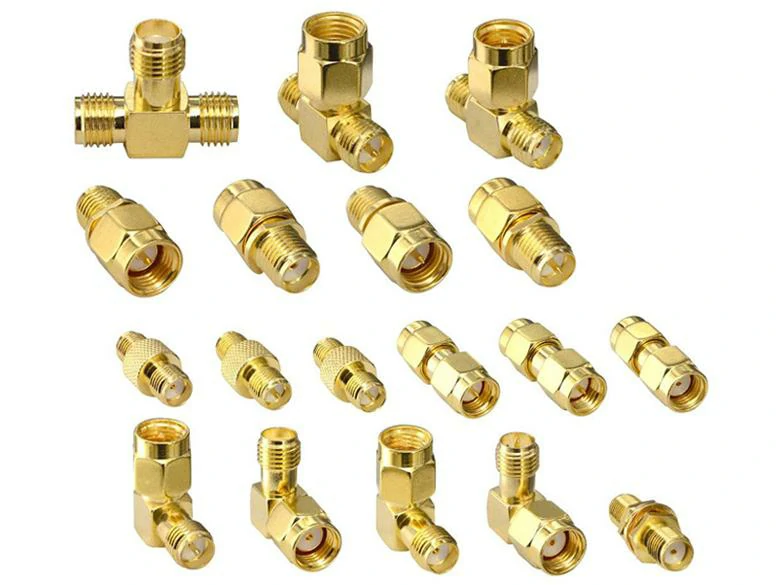
Product assortment showing different SMA adapter configurations, including straight adapters, right-angle adapters, tee adapters, male-to-male, male-to-female, and female-to-female designs for RF testing, antenna systems, and communication equipment.
The first mistake during adapter selection is usually choosing by appearance alone.
Two connectors may look similar but still cannot be connected correctly. SMA systems have different genders, structures, and installation requirements. Before ordering an adapter, the actual connection between two components needs to be confirmed.
Before selecting an SMA adapter, check these points:
| Check Item | Practical Question |
| Connector gender | Are both sides SMA male or SMA female? |
| Installation direction | Is a straight or right-angle structure needed? |
| Frequency range | Can the adapter support the working frequency? |
| Impedance | Is the RF system designed for 50Ω? |
| Usage condition | Testing environment or long-term installation? |
A correct adapter selection starts from the connection requirement, not from the product picture.
Why Can an SMA Adapter Affect RF Signal Performance?
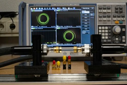
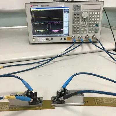
An RF laboratory setup using SMA adapters, coaxial test cables, circuit fixtures, and a vector network analyzer. The complete signal path can be measured to verify return loss, insertion loss, impedance matching, and RF connection stability.
An adapter adds another transition point into the RF path.
Every transition creates a possibility for small impedance changes. In a simple connection, the influence may be negligible. In a precision measurement system, multiple adapters connected together can gradually affect the final result.
Three common parameters are usually considered:
VSWR Changes Caused by Interface Mismatch
VSWR reflects how much RF energy returns toward the source because of impedance mismatch.
A poorly matched adapter may cause:
- Higher reflected power
- Less efficient signal transfer
- Measurement deviation
The problem is not always caused by the adapter itself. Incorrect connector matching, damaged contact surfaces, or combining different impedance systems can also create similar results.
For this reason, RF engineers often test adapters together with cables and instruments rather than evaluating the adapter alone.
Return Loss and Connection Stability
Return loss describes the amount of reflected signal in the RF path.
During product testing, return loss can reveal problems that are difficult to find through visual inspection.
For example:
A connector may appear normal externally, but an inaccurate internal contact position can create a small discontinuity.
In high-frequency applications, small mechanical differences may become electrical performance differences.
How Do SMA Adapter Structures Change the Connection Method?
In an RF project, the connector interface is often decided before the final assembly stage. The cable length, equipment port, and installation position may already be fixed. When two parts cannot be connected directly, changing the entire cable is usually not the first choice.
An SMA adapter provides another option.
For example, a test cable may already be terminated with an SMA male connector, while the device under test also has an SMA male port. The two parts cannot mate directly, even though they belong to the same connector family. A suitable adapter can solve this interface problem without modifying the original components.
The same situation appears frequently in:
- RF laboratory testing
- Antenna development
- Wireless module debugging
- Communication equipment integration
Different SMA adapter structures exist because the connection conditions are different.
A straight adapter, a right-angle adapter, and a tee adapter may all use SMA interfaces, but they solve different installation problems.
Why Are SMA Male and Female Adapter Configurations Different?
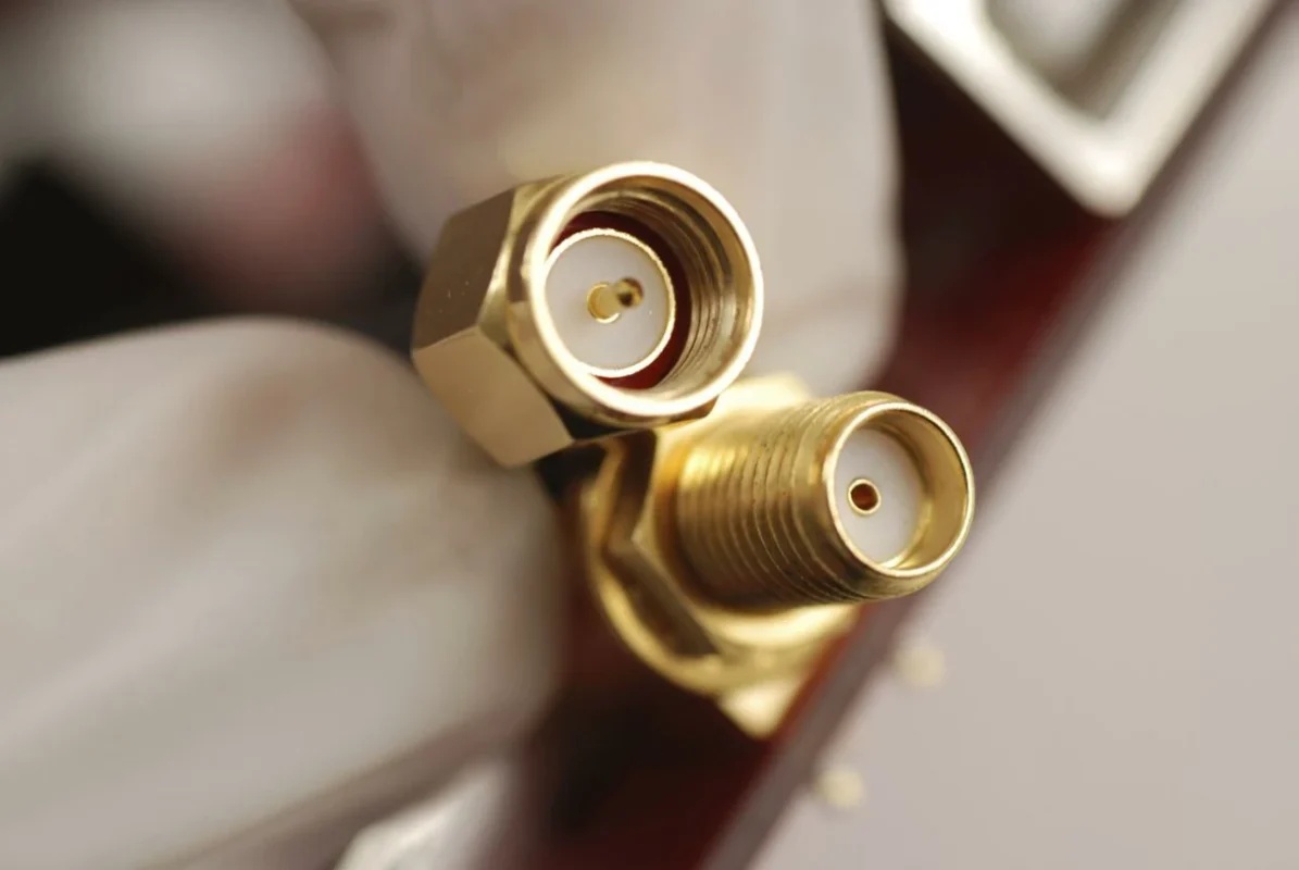
The SMA interface uses a male and female structure to complete the electrical connection. During connection, the two parts must maintain accurate alignment.
This is why choosing an adapter only by the connector name is not enough.
A male-to-female adapter is often used when two devices have opposite interfaces.
A female-to-female adapter is commonly used to join two SMA male cables.
A male-to-male adapter is useful when two equipment ports both use SMA female interfaces.
The correct configuration depends on the existing components in the RF chain.
What Should Be Checked Before Using an SMA Male to Female Adapter?
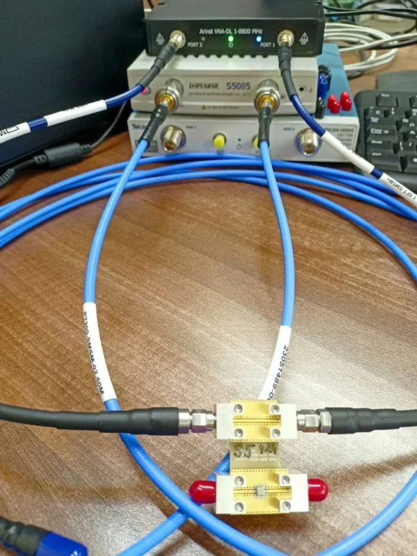
Laboratory test setup showing an SMA adapter connected between RF test cables and a vector network analyzer. This measurement configuration can be used to evaluate VSWR, return loss, insertion loss, and connection repeatability.
The SMA male to female adapter is one of the most frequently used RF adapter types.
It appears simple, but several details need confirmation before use.
The first point is the mechanical connection.
The adapter must match:
- Connector gender
- Thread specification
- Interface size
- Installation direction
A wrong gender selection may prevent connection or create poor contact.
The second point is electrical compatibility.
An SMA adapter used in a 6 GHz system and one used in a higher-frequency measurement setup may not have the same internal design.
For general RF connections, the adapter may only need to provide a stable connection.
For measurement applications, the adapter becomes part of the calibration path, so consistency becomes more important.
How Does SMA Adapter Selection Relate to Other Coaxial Adapters?
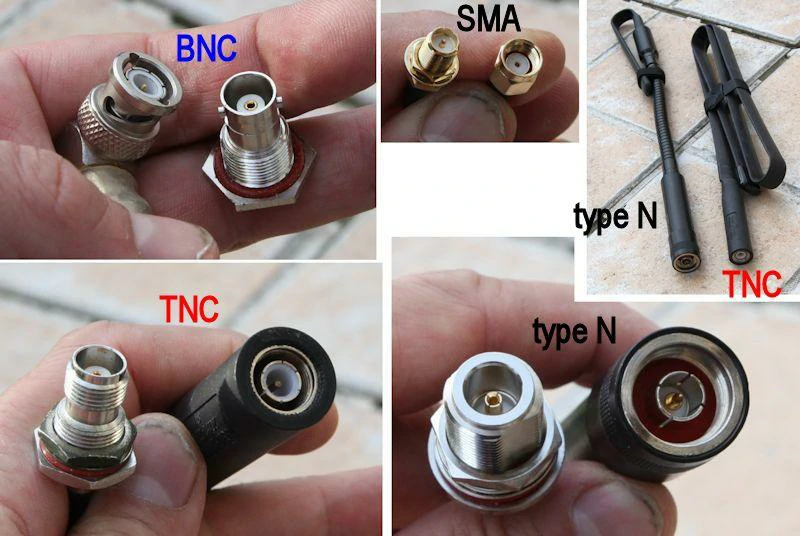
Visual comparison of common RF coaxial connector families, including BNC, SMA, TNC, and Type N connectors. The image helps engineers identify differences in connector size, coupling structure, center contact, and typical RF applications.
SMA is only one member of the coaxial adapter family.
In practical projects, engineers often need to connect different connector standards together.
The adapter should follow the existing RF system rather than forcing the system to match the adapter.
The selection process usually starts from the equipment interface, then moves to:
- Frequency requirement
- Power level
- Installation environment
- Mechanical limitation
Coaxial Adapter Selection Matrix
| Adapter Family | Typical Use | Selection Focus |
| SMA Adapter | RF modules and testing | Compact RF connection |
| N Adapter | Communication equipment | Outdoor and power requirements |
| BNC Adapter | Test equipment | Fast connection |
| TNC Adapter | Industrial RF systems | Threaded stability |
| MMCX Adapter | Small wireless devices | Space limitation |
How Do SMA Adapters Perform in Real RF Testing and Product Development?
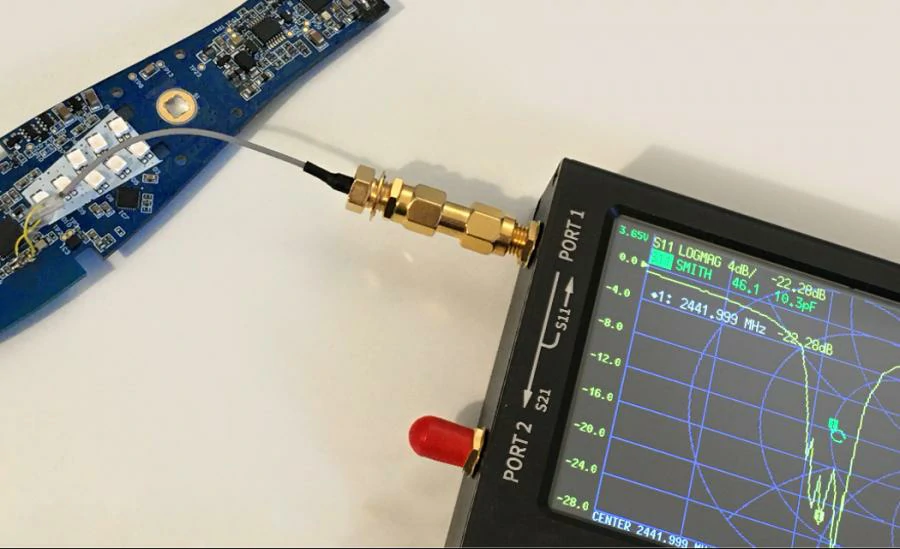
Practical RF development setup showing an SMA adapter and coaxial cable connecting a circuit board to a portable vector network analyzer. This configuration is commonly used for antenna tuning, wireless module debugging, impedance analysis, and return loss measurement.
In a real RF setup, an SMA adapter is rarely used alone.
It normally appears between a cable and a device, between two test instruments, or inside a temporary measurement configuration.
This means the adapter becomes part of the complete RF path.
During early prototype testing, an adapter may only be used to solve a connection problem. But when the project moves into performance verification, engineers start paying more attention to whether the adapter changes the measurement result.
A connection that works mechanically may still need further evaluation electrically.
For example, during VNA testing, replacing one adapter with another model can sometimes create small differences in:
- VSWR curve
- Return loss value
- Insertion loss result
These changes are usually related to the internal structure, contact accuracy, and manufacturing consistency of the adapter.
How Is SMA Adapter Performance Usually Verified?
There is no single test that defines the quality of an SMA adapter.
In many RF projects, evaluation combines electrical testing with physical inspection.
The first step is usually checking the basic specification:
- SMA male or SMA female
- Adapter structure
- Frequency requirement
- 50Ω impedance
- Application environment
After the basic information is confirmed, electrical testing can be performed.
Common measurements include:
VSWR Test
VSWR is often used to check whether the adapter creates an obvious mismatch in the RF path.
A higher VSWR result may indicate problems such as:
- Poor contact alignment
- Incorrect internal dimensions
- Interface damage
- Impedance discontinuity
Return Loss Measurement
Return loss provides another way to evaluate reflected energy.
For high-frequency systems, a small mechanical difference inside the adapter can influence the measurement result.
This is why RF test environments usually use consistent adapter models throughout the setup.
Insertion Loss Evaluation
When an RF path contains several components, every additional connection contributes some loss.
For example:
RF cable → SMA adapter → test cable → instrument
Each connection point becomes part of the total signal path.
For general applications, the effect may be small.
For precision measurement, reducing unnecessary connections helps maintain better repeatability.
What Information Should Be Provided for a Custom SMA Adapter?
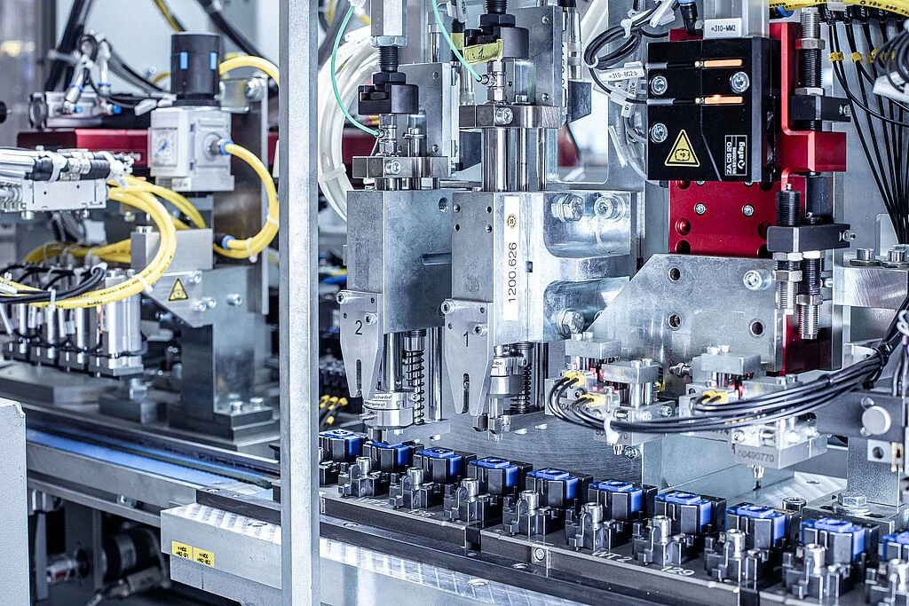
Industrial automation equipment used for precision component processing, assembly, and production inspection. Accurate manufacturing helps control the mechanical dimensions, center-contact alignment, and consistency required for SMA adapters and RF connectors.
Many SMA adapter requirements appear simple at first.
A customer may initially describe the request as:
“I need an SMA adapter.”
However, the actual product cannot be determined from this description alone.
The same SMA adapter name may represent different products:
- Different connector genders
- Different body structures
- Different frequency ranges
- Different installation methods
For a custom project, the more complete the initial information is, the easier it is to confirm the correct solution.
Useful information includes:
- Connection method
- Required SMA interfaces
- Operating frequency
- Installation space
- Expected RF performance
- Application purpose
For example, an adapter used for antenna installation and an adapter used for VNA calibration may have completely different requirements, even though both use SMA interfaces.
Custom SMA Adapter Requirement Table
| Requirement | Example Description |
| Connector type | SMA male / SMA female |
| Structure | Straight / right angle / tee |
| Frequency | Working frequency range |
| Impedance | 50Ω RF system |
| Application | Antenna, testing, communication |
| Mechanical size | Length and installation limitation |
| RF requirement | VSWR, loss requirement |
Where Are SMA Adapters Commonly Used?
The application of SMA adapters is closely related to the way RF systems are developed.
A few typical examples:
RF Laboratory Setup
In laboratories, engineers often change connection methods during testing.
An SMA adapter allows different cables and instruments to work together without producing a new cable assembly every time.
Typical equipment includes:
- Network analyzers
- Signal generators
- Spectrum analyzers
- RF test fixtures
FAQ
1. Why does my SMA cable need an adapter if both connectors are SMA?
Because “SMA” only describes the connector family.
Two SMA connectors may still have the same gender, making direct connection impossible.
For example, two SMA male cables require a suitable female-to-female adapter.
2. Will an SMA adapter reduce RF signal quality?
Any additional RF connection may introduce some influence.
The actual effect depends on:
- Adapter design
- Frequency range
- Manufacturing quality
- System sensitivity
In low-frequency applications, the effect may be minor. In precision RF testing, adapter performance becomes more important.
3.I need an adapter between two SMA ports. How do I know which one to choose?
First check the two connectors you already have.
Many connection problems come from choosing the wrong SMA gender. A quick look at the cable ends usually tells whether you need male-to-female, female-to-female, or another type.
4.Why does my SMA connector not screw together with another SMA connector?
The connector series may be the same, but the interface combination may not match.
For example, two male connectors cannot connect directly. In that case, an adapter is needed between them.
5.Can an SMA adapter be left installed on equipment?
Yes, in many applications it stays installed.
For test setups that are changed frequently, some users prefer removable adapters because cables and instruments need to be swapped often.
6.Does the adapter type matter if the cable already works?
It can matter.
A different adapter changes the connection point in the RF path. For normal connections this may not be noticeable, but measurement systems are more sensitive.
7.What information should I send when asking for an SMA adapter quote?
A product picture or drawing is usually helpful.
It is also better to include the connector type, quantity, working frequency, and where the adapter will be used.
