
The equipment label says 3 kV. The cable end uses a bayonet coupling. Someone in purchasing calls it “high-voltage BNC” and orders the closest-looking replacement.
That is enough to create a serious compatibility problem.
A connector does not become an SHV connector because it carries high voltage or resembles BNC hardware. The interface family, recessed contact geometry, approved mating part, cable insulation system, and working-voltage rating must all agree. A mechanically successful connection is not proof that the interface is safe to energize.
SHV identification should therefore begin with the equipment de-energized and the relevant drawing, datasheet, or part number available. If the connector cannot be positively identified, stop there. Do not use trial mating as the identification method.
How do you prove the connector is SHV before energizing the system?
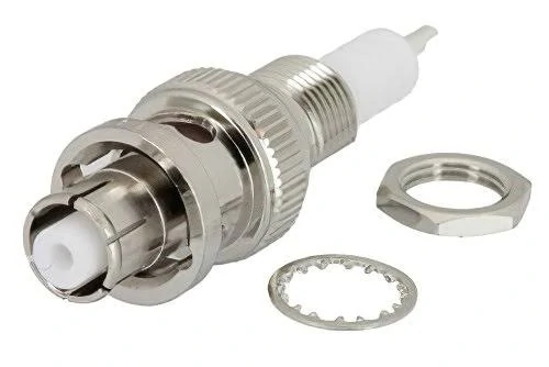
Panel-mount SHV connector shown with its mounting nut and lock washer. When selecting an SHV bulkhead connector, verify the panel cutout, panel thickness, rear clearance, mating interface, and approved mounting arrangement.
Start with the interface, not the voltage printed on the enclosure.
The SHV family uses a bayonet coupling, but the bayonet alone is weak evidence. BNC and MHV hardware can look similar in a small product photo. The more useful clue is the insulation surrounding the center contact. In an SHV mating pair, both pin and socket contacts are recessed within insulating material to reduce the chance of touching an energized conductor when the connectors are unmated.
That construction is part of the safety logic described for current SHV products. It is also why an SHV interface should not be treated as a high-voltage version of an ordinary BNC connector. Radiall’s current SHV documentation states that its SHV series is not intermateable with standard BNC or BNC HT/MHV hardware and uses protected center contacts.
Identify the protruding insulation and bayonet geometry before checking voltage labels
Inspect the cable side and equipment side separately. Record the coupling mechanism, insulation profile, contact position, mounting arrangement, and any visible manufacturer marking. Then compare those details with the equipment drawing or connector datasheet.
A useful identification sequence is:
- Find the equipment model and connector callout.
- Record any manufacturer name or part number.
- Compare the mating face with the approved drawing.
- Confirm both sides belong to the same SHV series.
- Check the specified mating part.
- Review voltage ratings only after the interface is confirmed.
The IEC 60498 high-voltage coaxial connector standard covers mating dimensions, construction, voltage ratings, test voltages, insulation requirements, and operating conditions for connectors used with nuclear instrumentation. The IEC currently lists a stability date of 2029. That makes it a useful interface and test-framework reference, but it does not replace the datasheet for the exact part number.
Separate the connector family from the equipment’s voltage label
A label such as “3 kV output” describes the circuit. It does not identify the connector.
The port might be SHV, MHV, a proprietary high-voltage interface, or another coaxial family selected by the equipment manufacturer. Even within the SHV family, different part numbers can have different working-voltage, test-voltage, frequency, cable, and environmental limits.
Use high voltage connector or high voltage coaxial connector as an application class. Use SHV only after the interface has been confirmed. This distinction should also appear in purchasing records. A vague line such as “high voltage coax connector, 5 kV” leaves too much room for substitution.
The TEJTE MHV and SHV connector category can help identify available configurations, but approval should still be based on the selected connector drawing and its matching part.
Do not release the replacement when the final row remains “No.” A missing connector identity is not a minor documentation gap in a high-voltage chain.
Which side should carry the recessed high-voltage contact?
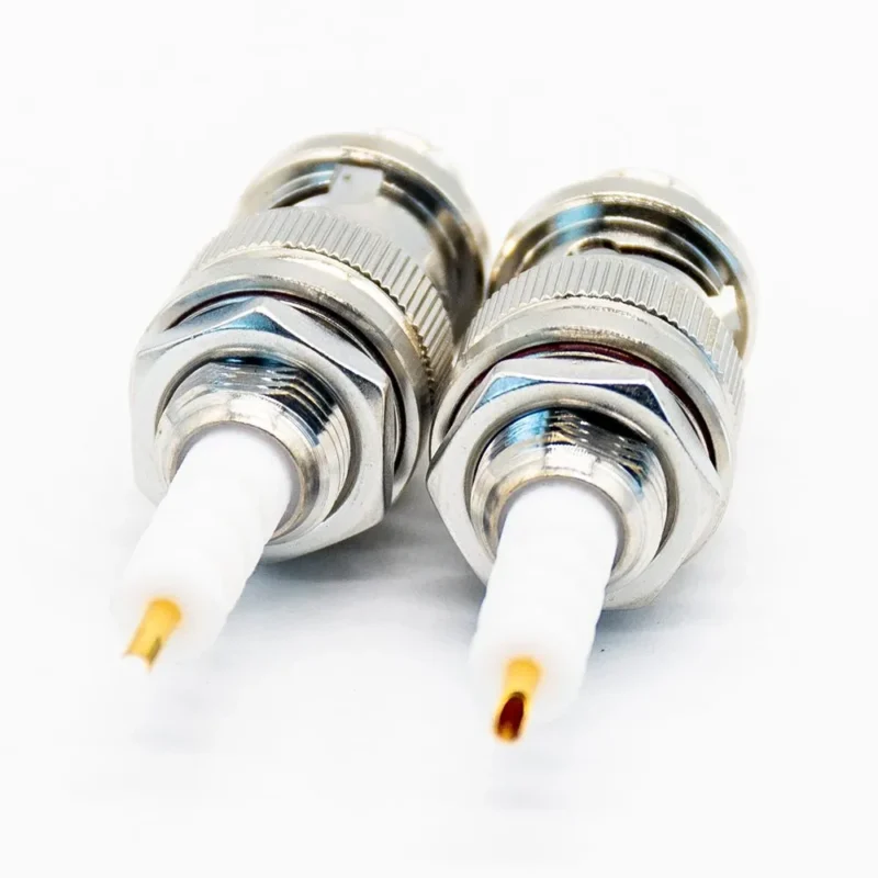
Do not define SHV gender by looking only for an exposed pin. That shortcut works poorly because the center contacts are deliberately protected by insulation.
Confirm the manufacturer’s designation—plug or jack, male or female—against the mating-face drawing. The cable connector may be described as a plug while the panel connector is listed as a jack or receptacle. The center-contact appearance alone can mislead buyers familiar with standard BNC hardware.
Keep the safety mating sequence in the design review
The interface is intended to keep the high-voltage conductor difficult to touch and to control the order in which conductive surfaces engage or separate. That protection depends on using the approved pair. A generic adapter, incorrect gender, damaged insulator, or lookalike connector can defeat the original design intent.
Inspect for cracked insulation, contamination, bent contacts, bayonet damage, and evidence of forced mating. Perform this check with the circuit isolated according to the equipment manufacturer’s safety procedure.
Separate cable-side and panel-side roles
A common system path is:
SHV cable plug → SHV panel receptacle → internal high-voltage circuit
It is common, not universal. Panel mounting, cable mounting, straight bodies, right-angle bodies, solder terminations, and crimp terminations may all exist within a connector family. “SHV” does not specify where the part mounts or which cable it accepts.
Both columns must be complete. If only the cable side has a confirmed part number, the mating pair has not yet been verified.
How do working voltage and withstand voltage change the part choice?
“Rated 5 kV” is not a complete SHV specification.
It may refer to continuous working voltage, a short dielectric-withstand test, an unmated connector, or a fully mated pair. AC and DC values cannot be exchanged casually, and a test voltage applied for a defined duration is not automatically a safe continuous operating voltage.
At minimum, record these conditions separately:
- Continuous working voltage
- AC or DC
- Dielectric-withstand or test voltage
- Test duration
- Mated or unmated condition
- Temperature, humidity, and altitude
- Applicable connector, cable, or complete assembly
The distinction matters. A part can pass a short high-voltage test while still being unsuitable for continuous operation at that same voltage.
Use the exact manufacturer rating rather than a generic SHV number
The letters SHV identify an interface family. They do not create one universal voltage rating.
For example, the current Radiall SHV R317 documentation distinguishes 10 kV DC test voltage for unmated connectors from 12 kV DC for a mated pair. Those are test-voltage conditions, not permission to operate every SHV connector continuously at 12 kV.
A buyer should never copy the highest number from a datasheet into the working-voltage field. Read the parameter name, condition, unit, and footnotes first.
Calculate the system voltage ceiling
Use this rule only when the values describe comparable working conditions. Do not compare an adapter’s short-duration withstand voltage with a cable’s continuous DC rating.
The lowest correctly defined working rating controls the chain. A higher-rated connector cannot compensate for a lower-rated cable or instrument port.
Match the cable dielectric to the connector before approving the assembly
An SHV cable is not ordinary coax fitted with a high-voltage connector.
The cable dielectric, jacket, shield, center conductor, termination geometry, temperature rating, and documented voltage capability all participate in the insulation system. Outside diameter matters for assembly, but physical fit is only one condition.
A cable may enter the rear body and still be wrong because:
- Its dielectric is not rated for the required voltage.
- The prepared insulation length reduces creepage distance.
- The shield or jacket diameter does not match the ferrule.
- The center conductor does not fit the contact termination.
- The cable bends too tightly behind the connector.
- The approved connector drawing lists a different cable group.
The RG cable guide is useful for comparing general coax construction and dimensions. High-voltage approval still requires the exact cable manufacturer, part number, and voltage data.
Do not approve the assembly from a generic entry such as “50-ohm HV cable.” Procurement needs the exact cable part number, especially when a production supplier proposes a substitution.
When should a bulkhead receptacle move the HV interface to the panel?
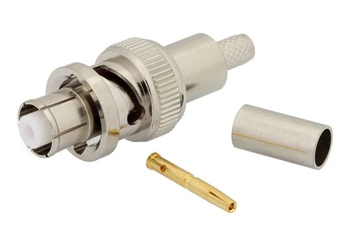
Exploded view of an SHV cable connector including the connector body, gold-plated center contact, and crimp ferrule. Correct contact and ferrule dimensions must match the specified coaxial cable before an SHV cable assembly is approved.
Repeated high-voltage mating should usually occur at a mechanically supported interface rather than directly on an internal circuit.
A typical arrangement is:
Internal HV circuit → panel-mounted SHV receptacle → external SHV cable assembly
The enclosure then carries cable weight, operator handling, and repeated bayonet engagement. Internal wiring remains protected from routine service loads.
Before machining the panel, verify:
- Connector part number and mounting drawing
- Panel cutout and permitted thickness
- Rear insulation clearance
- Shield-to-chassis bonding
- Internal conductor spacing
- Fastener and tool access
- Cable bend clearance
- Access for inspection and replacement
A mechanically strong installation can still be electrically poor if a rear terminal sits too close to grounded metal or the cable is forced into a sharp bend immediately behind the receptacle.
How do you prevent a BNC or MHV lookalike from entering the HV chain?
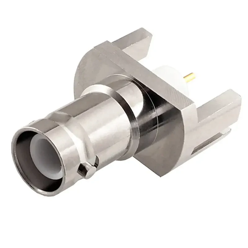
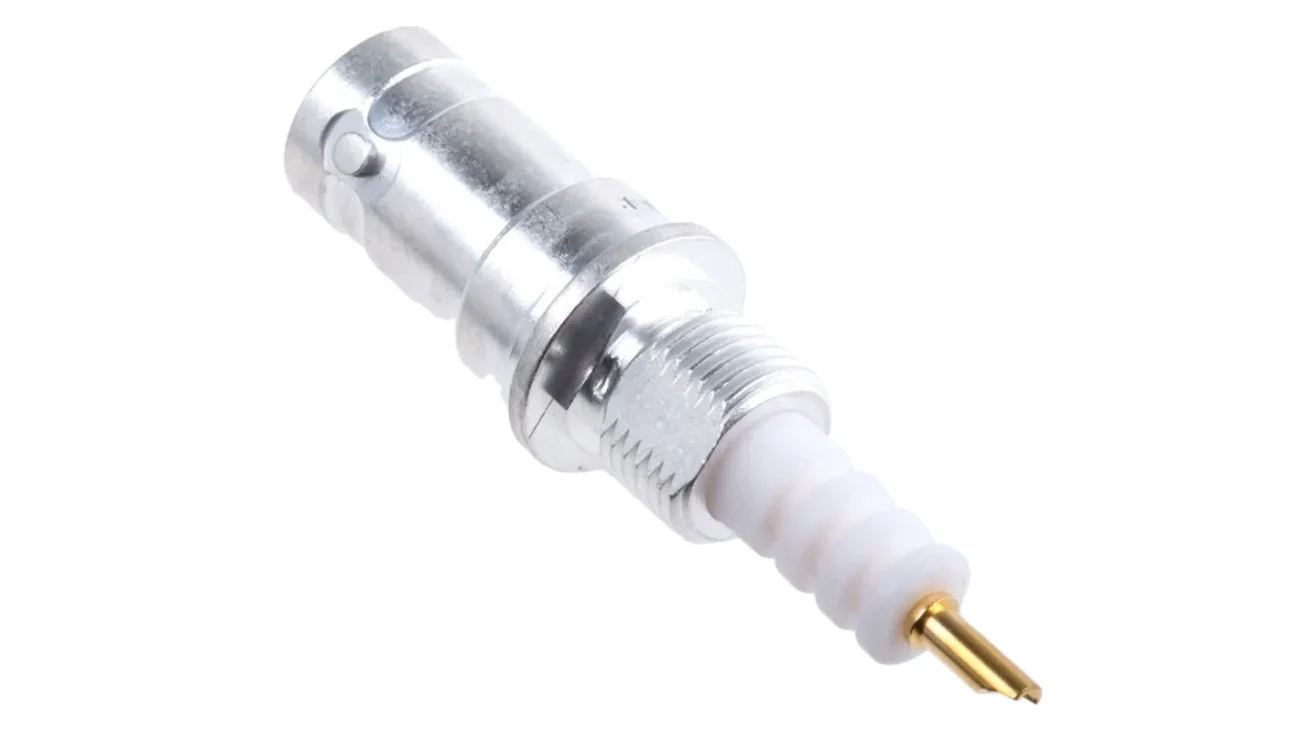
SHV coaxial connector with a board-mount structure and rear electrical terminal. Fixed connector configurations should be checked against the equipment drawing for interface geometry, mounting dimensions, clearance, and voltage requirements.
Physical resemblance should be treated as a hazard, not compatibility evidence.
Do not create purchasing cross-references such as “BNC equivalent to SHV.” They encourage a buyer or warehouse operator to select by coupling style rather than interface geometry and voltage documentation.
Use controls that remain visible after the engineering review:
| Mis-mating risk | Practical control |
| SHV confused with BNC | Family label plus approved reference sample |
| SHV confused with MHV | Approved mating part number |
| Low-voltage cable substituted | Locked cable part number |
| Generic adapter inserted | Engineering approval required |
| Wrong gender ordered | Mating-face drawing attached to PO |
| Wrong voltage value copied | Separate working and test fields |
Dedicated storage also helps. Do not place SHV, BNC, and MHV components in one generic “bayonet connector” bin. Use clear high-voltage labels, controlled part numbers, and protective caps that keep the insulating surfaces clean.
Set the test sequence before the first energized connection
High-voltage testing should not begin with an improvised bench setup.
Start with the system de-energized. Inspect the connector body, insulator, contact, cable strain relief, bayonet features, and mating fit. Cracks, contamination, a loose body, or evidence of forced mating should place the assembly on hold.
Then perform the project-approved low-voltage checks:
- Center-conductor continuity
- Shield continuity
- Center-to-shield isolation
- Mechanical mating verification
- Cable and connector part-number confirmation
Passing continuity proves only that a conductive path exists. It does not prove adequate insulation, correct voltage capability, or acceptable RF behavior.
Any dielectric-withstand, leakage, or energized high-voltage test must follow the equipment manufacturer’s procedure, the applicable laboratory safety rules, and an approved test plan. The article should not be used to select a test voltage or construct a high-voltage test fixture.
A “No” or blank field means the assembly remains de-energized.
How should an SHV adapter be evaluated without bypassing the safety intent?
An adapter changes an interface. It does not upgrade the voltage capability of the components connected after it.
This is particularly important with an SHV-to-BNC adapter. The SHV side may belong to a high-voltage coaxial system, but the BNC connector, cable, and instrument port on the other side retain their own limits. The maximum permitted system voltage remains controlled by the lowest-rated component.
Reject vague descriptions such as “SHV adapter, high voltage.” The BOM should identify both interfaces, gender, impedance where relevant, manufacturer part number, approved mating parts, and the conditions under which the transition may be used.
Which measurements belong in first-article qualification?
A first article should pass more than a continuity test.
Continuity and shield checks confirm that conductors are connected. Center-to-shield isolation checks for an obvious short or insulation failure. Neither result proves that the assembly can safely operate at the requested voltage.
RF testing is necessary only when the circuit carries RF energy or fast pulses. SHV frequency capability is not universal. For example, Radiall’s referenced R317 series is specified as a 50-ohm interface through 2 GHz, but that figure should not be transferred to another SHV part number or an unverified cable assembly.
Record temperature, humidity, connector condition, cable bend state, and whether the part was panel-installed. A result without its test condition is difficult to use during a later supplier or customer dispute.
Build the supplier specification around the lowest-rated component
A purchase request reading “5 kV SHV cable” leaves several decisions to the supplier. That is where substitutions begin.
Write working voltage and test voltage in separate RFQ fields. State AC or DC, test duration, mating condition, cable part number, connector gender, bulkhead part number, approved mate, operating temperature, and frequency only when the circuit carries RF or pulses.
A controlled BOM should connect the complete path:
SHV cable connector P/N → cable P/N and length → panel receptacle P/N → equipment port → approved adapter, if any
Also define handling requirements. Insulator surfaces should be protected from impact and contamination. High-voltage labels must remain visible. Hot mating should not be permitted unless the equipment and connector system were specifically designed and approved for it.
SHV connector RFQ form
This form is more useful than asking a supplier to recommend “something similar.” It makes any proposed substitution visible before samples are assembled.
How should incoming SHV lots be screened before release?
Visible insulation and interface defects deserve 100% inspection. Check for cracks, chips, contamination, bent contacts, damaged bayonet features, loose bodies, wrong labels, and unapproved cable markings.
Critical dimensions and mating fit can be sampled according to product risk, supplier history, lot size, and the customer’s quality plan. Use a controlled reference mate rather than an unidentified connector taken from production.
Complete high-voltage qualification is different from routine visual IQC. It may be performed during supplier approval, after a process or material change, at defined lot intervals, or when required by the customer. It should not become an improvised manual test at the incoming-inspection table.
| Characteristic | Method | Suggested control | Failure action |
| Interface identity | Visual and drawing | 100% | Quarantine lot |
| Insulator condition | Visual | 100% | Reject or sort |
| Cable part number | Marking check | 100% | Hold lot |
| Contact position | Measurement | Risk-based sample | Expand sample |
| Mechanical mating | Approved reference mate | Risk-based sample | Investigate |
| Isolation | Electrical test | Quality plan | Hold lot |
| HV qualification | Approved procedure | Defined by risk | Reject/investigate |
| RF test, if required | VNA or pulse setup | RFQ-defined | Investigate |
FAQ
How can I confirm a connector is really SHV?
Check the interface family, bayonet geometry, recessed insulation, manufacturer part number, equipment drawing, and approved mating part. A high equipment voltage or BNC-like appearance does not prove that the port is SHV.
Is every SHV connector rated for exactly 5 kV?
No. Working voltage, test voltage, AC/DC condition, test duration, and mated or unmated state vary by part number. Use the exact datasheet value under the required operating condition.
Can any coax cable be used if it physically fits?
No. The cable dielectric, voltage rating, jacket and shield dimensions, center conductor, termination geometry, temperature range, and approved cable assignment must also match.
Why should SHV not be treated as a high-voltage BNC or MHV substitute?
SHV uses protected contact and insulation geometry intended to reduce accidental contact and mis-mating risks. Similar bayonet hardware does not make BNC, MHV, and SHV interchangeable.
Does every SHV connector have the same frequency range?
No. Frequency capability depends on the exact connector, cable, termination, and assembly. If RF or fast pulses are involved, specify the operating band and verify the complete path.
Should every incoming lot receive a full HV withstand test?
Not necessarily. Visual inspection, identity checks, and cable verification may be performed on every part, while dimensional, isolation, and high-voltage qualification can follow an approved risk-based quality plan.
An SHV connector should never be approved from its name or appearance alone. Before ordering, send the connector interface, gender, working voltage, test condition, cable part number, mating receptacle, operating environment, and required inspection report. That information allows the supplier to review the complete high-voltage coaxial path instead of quoting one isolated component.
