
A cable assembly may look correct and still fail after it enters production.
This happens with RF systems more often than expected. During sample testing, the cable is usually short, placed on an open bench, and connected under ideal conditions. The signal looks normal, the connector fits, and the test result passes.
The situation changes after installation.
The same cable may be routed beside a power supply, placed near a motor drive, or installed inside a crowded enclosure with several electronic modules operating together. Noise that was invisible during the first test can appear later as unstable readings, communication errors, or inconsistent wireless performance.
Many engineers first check the RF module or antenna when this happens.
The cable is often checked last.
That is a mistake.
The cable is part of the RF transmission path. Its construction determines how the signal is protected from the surrounding environment. A shielded cable is not only used to transfer a signal from point A to point B. It also controls how electromagnetic interference enters or leaves the cable.
For RF applications, cable selection usually involves several factors at the same time:
- Shielding structure
- Impedance
- Frequency range
- Cable loss
- Connector compatibility
- Installation conditions
A cable with strong shielding but unsuitable electrical characteristics can still create problems. The correct choice depends on the complete RF system, not one specification number.
Why Do RF Systems Need Shielded Cables?
This image shows the basic structure of a shielded coaxial cable, including the center conductor, dielectric material, shielding layer, and protective jacket. The shielding structure helps reduce electromagnetic interference in RF communication systems.
RF signals operate at frequencies where unwanted electromagnetic energy can easily become a problem.
A nearby switching circuit, digital processor, wireless transmitter, or industrial controller may generate interference around the cable. If the cable does not provide enough protection, this interference can couple into the signal path.
This is especially important for low-level RF signals.
For example, an antenna cable connected to a receiver is not carrying a large power signal. The received signal may already be weak before reaching the RF module. Additional noise introduced through the cable path reduces the available signal margin.
A shielded coaxial cable uses a conductive layer around the inner conductor to reduce this type of interference.
The basic structure normally includes:
| Cable Part | Practical Function |
| Center conductor | Transfers RF signal |
| Dielectric material | Maintains spacing and impedance |
| Shield layer | Blocks unwanted electromagnetic coupling |
| Outer jacket | Protects against mechanical damage |
The shield layer can be made in different ways. Some cables use foil shielding, some use braided shielding, and some combine multiple layers.
The choice depends on where the cable will be used.
A cable inside a controlled laboratory environment may not need the same construction as a cable installed next to industrial equipment.
How Does Shielding Protect RF Signals in Real Installations?
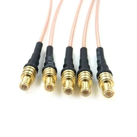
An RF cable assembly consists of a coaxial cable and connector interfaces designed for stable microwave and wireless signal connections. Proper cable selection affects frequency performance and signal quality.
This is why RF cable assembly inspection usually includes more than checking whether the connector is attached.
Depending on the application, suppliers may verify:
- Shield continuity
- VSWR
- Insertion loss
- Return loss
- Cable dimensions
- Connector installation quality
A continuity test can confirm that the circuit is connected. It cannot confirm that the RF path is working correctly.
Where Are Shielded Cables Used?
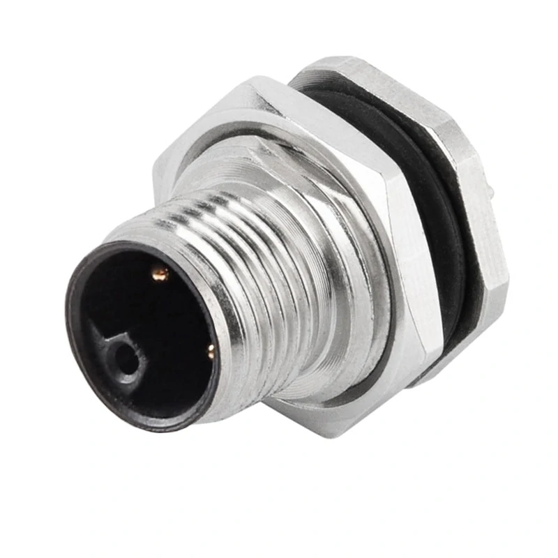
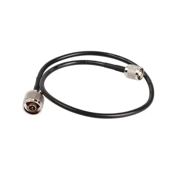
N type RF cable assemblies provide durable connections for outdoor and industrial RF systems. Shielded coaxial construction helps maintain signal integrity in environments with electromagnetic interference.
Typical applications include:
| Application | Cable Type | Main Concern |
| RF test equipment | RF cable assembly | Measurement repeatability |
| Antenna systems | Antenna cable | Signal loss and noise |
| Wireless devices | WiFi antenna cable | Space and interference |
| GPS equipment | GPS antenna cable | Weak signal protection |
| Industrial communication | Shielded communication cable | EMI environment |
In wireless equipment, the cable between the antenna and the main board is often short, but the requirements can still be strict. A small difference in cable loss or connector quality may affect the final system performance.
In industrial environments, the challenge is usually different.
Shielded Cable vs Unshielded Cable: What Should Buyers Consider?
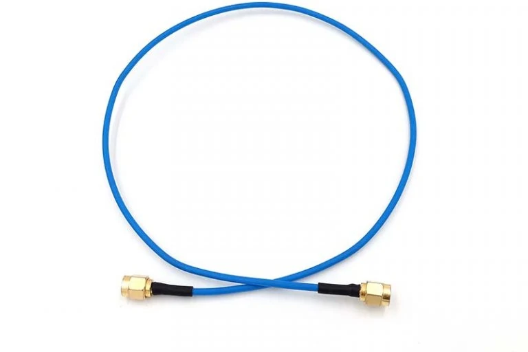
SMA RF cable connectors provide compact and reliable connections for high-frequency applications. Connector selection should match cable impedance, frequency range, and system requirements.
The choice between shielded and unshielded cable depends on the working environment.
An unshielded cable may be acceptable for simple signal transmission where interference sources are limited. It becomes risky when the cable runs through an environment with strong electromagnetic noise.
Shielded vs Unshielded Cable Comparison
| Item | Shielded Cable | Unshielded Cable |
| EMI protection | Better protection against external interference | Limited protection |
| RF applications | Suitable for antenna and communication systems | Used mainly in low-noise environments |
| Cable structure | Includes foil, braid, or multi-layer shield | No dedicated shield layer |
| Flexibility | May decrease with additional shielding | Usually easier to route |
| Cost | Higher manufacturing cost | Lower cost |
The practical question is not whether shielded cable is always better.
The question is whether the cable matches the environment where it will operate.
For RF buyers, a complete specification should include the cable type, impedance, operating frequency, length, connector interface, and installation condition. This information prevents incorrect substitutions and reduces problems after delivery.
How Does Shielding Structure Affect Cable Performance?
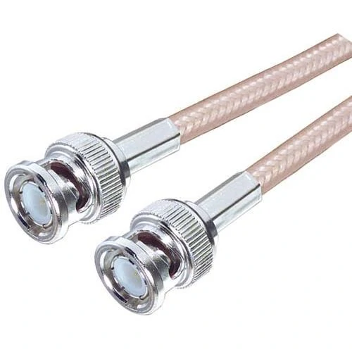
BNC RF cable assemblies provide quick-connect coaxial interfaces for various electronic applications. Shielded cable construction helps reduce unwanted electromagnetic interference during signal transmission.
Two cables can both be called “shielded cable” and still behave differently in an RF system.
The reason is the shield construction.
When engineers discuss cable shielding, the conversation usually goes beyond whether a cable has a shield layer. The actual question is: what type of shield is used, and is that structure suitable for the interference environment?
Different shield designs provide different levels of protection, flexibility, and manufacturing difficulty.
For RF cable assemblies, the shield design also affects the termination process. A supplier needs to consider how the shield connects with the connector body, because a good cable design can still lose performance if the termination is inconsistent.
How Do Foil and Braid Shields Compare in RF Cables?
Foil and braid shields are often used together because they solve different problems.
A simplified comparison:
| Shield Type | Main Advantage | Possible Limitation | Common Use |
| Foil Shield | High coverage, good high-frequency protection | Lower mechanical strength | Compact RF cables |
| Single Braid | Flexible and durable | Lower shielding than multi-layer designs | General RF connections |
| Foil + Braid | Balanced protection and flexibility | Higher cost | Most RF coaxial applications |
| Double Braid / Multi-layer | Strong interference protection | Larger diameter and reduced flexibility | Industrial and precision systems |
In practical RF applications, foil and braid combinations are common because they provide a better balance.
For example, a cable used for laboratory testing may require stable shielding performance because nearby equipment can affect measurement results. A cable installed inside a consumer device may prioritize diameter and flexibility.
The “strongest” shield is not always the correct choice.
How Should Shield Coverage Match the Installation Environment?
The installation environment should determine the shielding requirement.
A common mistake during sourcing is selecting a cable based only on frequency rating. Frequency compatibility matters, but it does not describe the entire operating condition.
A 50Ω cable used in an industrial environment may face different challenges compared with the same cable used inside a communication device.
Before selecting shielding, buyers should consider:
- Distance from noise sources
- Cable routing path
- Equipment enclosure design
- Operating frequency
- Required signal accuracy
- Mechanical movement
For example, a cable routed next to a motor controller may need stronger shielding than a cable installed inside a shielded equipment enclosure.
Another issue appears during production changes.
A prototype may use a short cable placed away from interference sources. During mass production, the cable route may change because of enclosure limitations. The original cable may still fit mechanically, but the RF environment has changed.
This is why cable selection should include installation details, not only product specifications.
Shield Structure Selection Matrix
The following matrix can be used as a practical starting point when selecting shield construction.
| Shield Structure | Protection Level | Flexibility | Typical Application |
| Foil Shield | Medium | High | Compact signal connections |
| Single Braid | Good | Good | General RF cable applications |
| Foil + Braid | High | Medium | Antenna and communication systems |
| Double Shield | Higher | Medium-Low | Industrial RF environments |
| Multi-layer Shield | Very High | Lower | Precision measurement systems |
This matrix is not a replacement for RF testing, but it helps buyers narrow down suitable cable structures before requesting samples.
A supplier recommendation should consider the complete cable assembly, including connector type, cable diameter, frequency range, and expected installation conditions.
How Do You Select Shielded Coaxial Cables for RF Applications?
Selecting a shielded coaxial cable requires more than confirming that the cable has a shield.
The cable must match the RF system.
Many sourcing problems happen because buyers provide only a product name, such as “SMA cable” or “RF cable,” without specifying the electrical requirements.
For RF applications, the cable specification normally needs to include:
- Impedance
- Frequency range
- Cable length
- Attenuation requirement
- Connector interface
- Shield structure
- Installation environment
A cable assembly is a complete RF path. Changing any part may affect the final result.
How Does Impedance Affect Shielded RF Cable Selection?
A cable may physically connect to a connector and still be electrically unsuitable.
This is one reason RF buyers should avoid selecting cables only by connector appearance.
The connector interface, cable impedance, and equipment specification must match together.
How Should Frequency Range Influence Cable Selection?
Frequency rating determines whether the cable can support the intended application.
A cable used near its maximum frequency may experience higher attenuation and less stable performance compared with a cable operating with additional margin.
For example, a low-frequency application and a microwave measurement application may both use coaxial cable, but the cable construction requirements are different.
Higher-frequency systems usually require closer control of:
- Cable geometry
- Dielectric material
- Shield structure
- Connector transition
- Manufacturing consistency
The connector is also part of this limitation.
A high-frequency connector attached to an unsuitable cable does not automatically create a high-frequency assembly.
What Cable Construction Details Should Buyers Confirm?
Before ordering a shielded coaxial cable assembly, the specification should include the details that affect production.
A cable that works for a short prototype connection may not be suitable for thousands of production units. Production consistency depends on controlling the details before manufacturing starts.
Why Does a Shielded Cable Sometimes Fail Even With Good Specifications?
A cable specification sheet may look acceptable, but the installed assembly can still create problems.
This situation appears frequently during project transfer from engineering samples to production units.
The sample cable is tested on a workbench. The distance is short, the cable routing is simple, and there are few nearby interference sources.
The production version is different.
The cable may run through a narrow enclosure, pass beside a power module, or be installed together with other wiring harnesses. The electrical environment changes, even though the cable model remains the same.
This is why RF cable selection cannot rely only on one parameter.
A shielded cable with excellent interference protection may still introduce unnecessary loss in a long transmission path.
A low loss RF cable may reduce attenuation, but it may not solve a problem caused by electromagnetic interference.
The first question during troubleshooting is usually not:
“Which cable has better specifications?”
It is:
“What changed between the test setup and the final installation?”
How Should Engineers Balance Shielding and Cable Loss?
Different applications create different priorities.
A short connection between an RF module and antenna may require flexibility and good shielding because the cable is installed close to digital circuits.
A long antenna feeder cable has another challenge. Even in a clean environment, the signal can gradually decrease as it travels through the cable.
Consider these situations:
| Installation Condition | Possible Issue | Cable Consideration |
| Near switching power supply | Noise enters signal path | Stronger shield construction |
| Long distance transmission | Signal attenuation | Lower loss cable design |
| RF laboratory measurement | Test variation | Stable electrical performance |
| Small equipment enclosure | Limited routing space | Flexible cable structure |
The choice is not always between “shielded” and “low loss.”
Many RF cable assemblies require both.
For example, a test cable used with a VNA needs controlled loss because measurement results depend on repeatability. At the same time, poor shielding can allow surrounding signals to affect the measurement.
What Should Be Checked Before Replacing an RF Cable?
When a cable assembly causes problems, replacing it immediately is not always the best first step.
A small mechanical change can affect RF behavior.
For example, excessive bending may change the internal geometry of the coaxial cable. The cable may still pass continuity testing, but the RF characteristics can change.
The same situation can happen at the connector termination area.
A connector that looks correctly installed may have incomplete shield contact or inconsistent assembly quality.
For this reason, RF troubleshooting usually starts from the complete cable assembly rather than the cable material alone.
This decision path is useful during supplier communication because it helps separate interference problems from transmission loss problems.
How Are Shielded Cables Verified Before Delivery?
A cable can pass basic inspection and still require additional RF testing.
Insertion Loss Test
Used to measure signal loss through the cable assembly.
Return Loss Test
Used to evaluate reflected signal caused by discontinuity in the RF path.
A continuity test only confirms that the conductor is connected.
It does not show whether the cable performs correctly at the operating frequency.
This difference becomes more important as frequency increases.
Shielded Cable Incoming Inspection Checklist
| Inspection Point | Verification Method |
| Cable specification | Match order requirement |
| Impedance | Confirm 50Ω or 75Ω |
| Frequency range | Check application band |
| Shield construction | Confirm foil/braid structure |
| Connector interface | Verify type and gender |
| Cable length | Measure tolerance |
| Shield connection | Check continuity |
| RF performance | VSWR / insertion loss when required |
For repeat production orders, this type of inspection record helps maintain consistency between batches.
A cable that works in the first batch should not rely only on visual similarity for future shipments.
What Information Should Be Included in a Shielded Cable RF Request?
Many sourcing problems start with incomplete descriptions.
A request like:
“Need shielded RF cable with SMA connector.”
does not define the complete assembly.
The supplier still needs to confirm:
- SMA male or female?
- Cable type?
- Operating frequency?
- Length?
- Impedance?
- Required shielding level?
- Application environment?
These details may seem unrelated to RF performance, but they affect production repeatability when order quantities increase.
FAQ
Can a shielded cable solve every interference problem?
No. Cable shielding is only one part of the RF system. Grounding, routing, connector termination, and surrounding equipment can also affect interference.
Why does an RF cable pass continuity but fail testing?
Because continuity checks electrical connection only. RF measurements evaluate signal behavior at the working frequency.
Should buyers always choose the cable with stronger shielding?
Not necessarily. Additional shielding may increase cable diameter and reduce flexibility. The cable should match the installation environment.
Is low loss cable always better for RF systems?
No. Lower attenuation is useful for long transmission paths, but it does not replace proper shielding when interference is the main issue.