RF Cables: The Ultimate Guide
July 19,2025
RF (Radio Frequency) cables are crucial for transmitting high-frequency signals in many systems – from telecommunications and radar to cable TV and broadcast equipment . RF signals occupy roughly the 20 kHz–300 GHz range of the electromagnetic spectrum , and RF cables are specifically designed to carry these signals with minimal loss. Typically these are coaxial cables: a copper center conductor surrounded by dielectric insulation, a braided or foil shield, and an outer jacket. This coaxial structure allows RF cables to carry high-frequency signals with low attenuation . In this guide we’ll cover what RF cables are, how they differ from other cable types, the common variants and connectors, signal loss considerations, and practical applications.
What is RF (in Cable)?
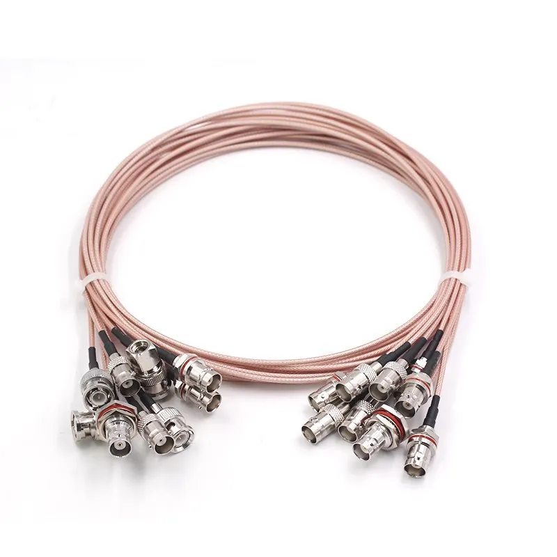
RF coaxial cables are integral to telecom, video broadcasting, and RF communication systems. They enable the efficient transmission of high-frequency signals while minimizing signal loss and protecting from interference.
“RF” stands for Radio Frequency, referring to the portion of the spectrum used in wireless communications – roughly from 20 kHz up to 300 GHz . In a cable context, “RF” simply means the cable is carrying those radio-frequency signals. Practically speaking, an RF cable is usually a coaxial cable optimized for RF use. Coaxial cables are defined as transmission lines that can carry high-frequency electrical signals with low losses . For example, one source notes “RF cable, also called coaxial cable, is a wire and signal transmission line… generally composed of four layers: copper conductor, plastic insulator, mesh conductor (shield), and an outer jacket” . In other words, an RF cable is a coaxial cable with proper shielding and impedance for RF signals. The shielding (copper braid or foil) protects the signal from external noise, which is why “the RF cable is a type of coaxial cable [that] possesses a shield to protect it from external interference” .
RF Cable vs. HDMI
RF (coax) cables and HDMI cables serve very different purposes. RF cables carry analog or digitally modulated RF signals (for TV broadcasts, radio antennas, etc.), whereas HDMI is a purely digital interface for high-definition audio/video. In other words, they are not interchangeable. HDMI cables transmit high-speed digital audio/video bitstreams, while RF coaxial cables transmit broadcast signals over radio frequencies. For example, one guide notes “On the other hand, HDMI cables efficiently transmit digital and audio signals,” whereas RF coaxial cables carry RF signals . In practice, you cannot simply swap an RF cable for an HDMI cable – TV sets use RF inputs (antenna/coax) for broadcast signals, and HDMI ports for HDMI sources. RF cables typically produce lower image quality than HDMI because RF broadcast signals are often analog or compressed, whereas HDMI carries uncompressed digital data.
What is an RF Coaxial Cable?
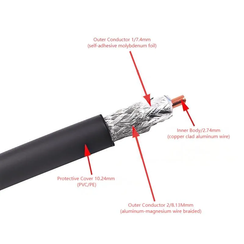
Coaxial cables are widely used in RF applications due to their ability to transmit high-frequency signals with minimal loss. The shielded structure protects the transmitted signals from external interference, ensuring reliable signal integrity in various telecommunications and broadcasting systems.
Coaxial cable is a special type of RF cable. It has a center conductor (solid or stranded copper), surrounded by an insulating dielectric. Around that is a conductive shield (braid or foil), and finally an outer jacket. This concentric arrangement keeps the signal confined (hence “co-axial”) and maintains a constant impedance. As Wikipedia explains, “Coaxial cable is a type of transmission line, used to carry high-frequency signals with low losses” . In RF applications, common impedance values are 50 Ω (for radio transmitters, test equipment) and 75 Ω (for video and TV). For example, one source notes that baseband (radio-frequency) coaxial cables like RG-8 or RG-58 have 50 Ω impedance, while broadband TV cables like RG-59 have 75 Ω . In practical terms, RG-58 and similar 50Ω cables are used in RF communication and data links, whereas RG-59/RG-6 (75Ω) are used for TV/video.
RCA cable connectors (red/green/blue) are examples of common RF coaxial terminations used for analog A/V signals . RF coaxial connectors are designed to maintain the cable’s characteristic impedance across the connection . The innermost conductor of one cable is joined to the innermost conductor of the next, and the shields mate together, ensuring signal continuity. Common termination methods include crimping or soldering with special crimping tools and cable cutters. A proper coax stripper/cutter makes a clean cut on the cable end, and a crimp tool or compression tool secures the connector. For example, terminating a BNC or F-type connector on RG-6 requires a specific crimp die. Many DIY RF cable kits include an RF cable crimping tool and matching connectors.
Common Types of RF Coaxial Cables
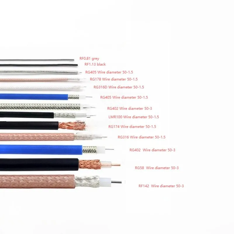
Different RF cables are designed for specific applications. 50Ω cables like RG-58 are typically used for RF communication, while 75Ω cables like RG-59 are often used for video and broadcast applications, each offering tailored impedance for optimal performance in their respective fields.
RF cables come in many types suited to different uses, impedances, and frequencies. Key variants include:
- 50Ω Coaxial Cables (Radio Frequency): Examples are RG-58, RG-213, LMR-240, etc. These are used for RF/microwave links, ham radio, WiFi antennas, and instrumentation. They typically handle up to ~6 GHz (depending on the cable) with moderate loss. These are often called “RF coax” in radio gear contexts .
- 75Ω Coaxial Cables (Video/TV): Examples are RG-59, RG-6, Belden 9913, etc. These have 75 Ω impedance and are standard for cable TV, satellite, CCTV, and antenna feeds. They exhibit lower loss for video frequencies. For instance, RG-59 (75Ω) is common for analog video, and RG-6 (75Ω) for digital cable/satellite.
- Triaxial Cable: Like coax but with a second shield. Used in broadcast/test labs (extra shielding). Not typically called “RF cable” by laymen.
- Twinaxial Cable: Two inner conductors with shield. Used for balanced high-speed digital links (e.g. data centers, some communications) – carries RF signals differentially.
- Flat RF Cable: Some specialty coax cables have a flat, ribbon-like form factor for tight spaces (e.g. between walls or floors).
- Rigid and Semi-Rigid Coax: Solid copper coax (semi-rigid/air-dielectric) used for fixed high-power or microwave interconnects.
- Precision RF Assemblies: Custom low-loss cables with hand-soldered connectors (often sold by precision cable makers).
Each type has different impedance and loss characteristics – not all RF cables are the same. Even cables with the same impedance can differ in attenuation: for example, a 100 MHz signal sees about 4.9 dB loss per 100 ft in RG-58, but only ~2.0 dB/100ft in RG-6 . At 1 GHz the difference is dramatic (RG-58 ~32.0 dB/100ft vs RG-6 ~6.1 dB/100ft ). Thicker coax or better dielectric gives lower loss. Low-loss cables and precision assemblies (sometimes marketed as “RF precision cables” or by brands like Tejte, Belden, etc.) ensure minimal signal attenuation for high-frequency use.
RF Cable Impedance and Specifications
RF cables are specified by their characteristic impedance (commonly 50Ω or 75Ω), frequency range, and attenuation. A 50Ω cable is usually used for RF/microwave transmission, whereas 75Ω is used for video/cable-TV signals. It’s crucial to match impedance at connectors and devices to avoid reflections. Cable specs include insertion loss (dB per 100 ft or per meter) and velocity factor. For planning links, engineers use RF cable loss charts or calculators. For instance, data from a cable attenuation chart shows how loss rises with frequency for different cables . Online calculators (often from manufacturers) allow you to enter cable type, length, and frequency to get the expected loss. Typical values: RG-6 (75Ω) might lose ~0.3 dB/meter at 100 MHz, while RG-58 (50Ω) loses ~0.9 dB/m at 100 MHz.
RF Cable Connectors and Types
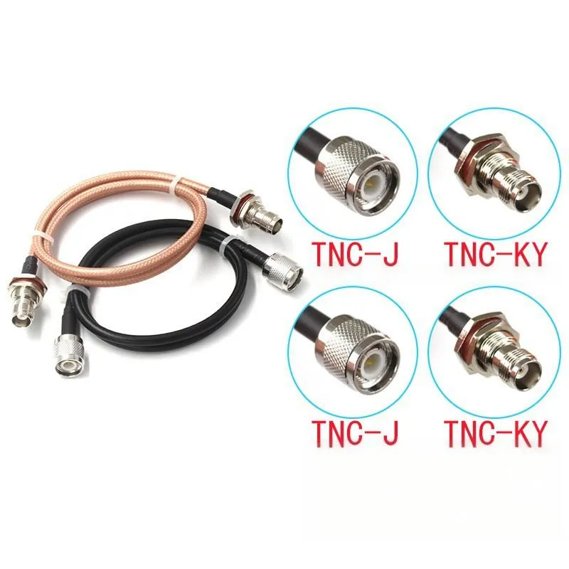
TNC connectors are widely used in microwave and RF systems for applications where secure connections are crucial. Their threaded design ensures a stable connection, minimizing the risk of signal degradation at higher frequencies.
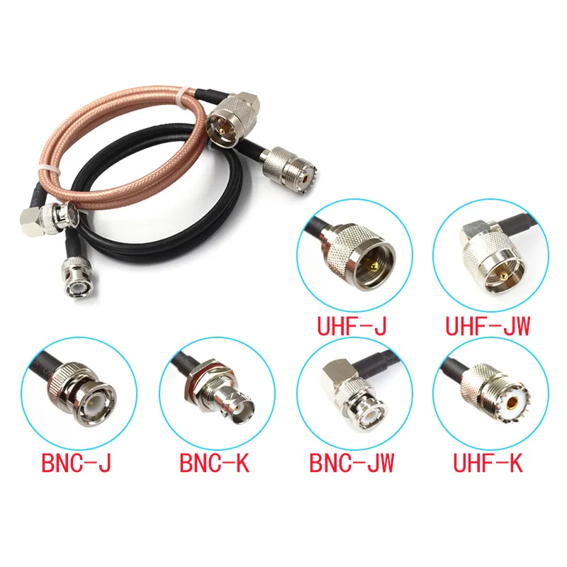
UHF and BNC connectors are commonly used in video, CCTV, and test equipment applications. BNC connectors are particularly popular for low-frequency applications, while UHF connectors are often used in legacy VHF/UHF radio systems.
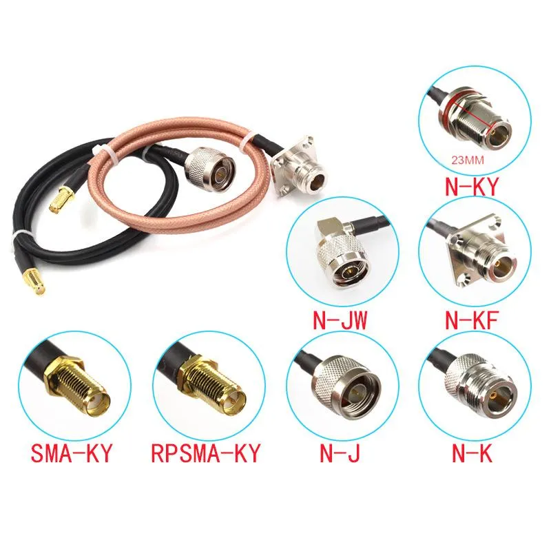
The N and SMA connectors are critical components in high-frequency telecom, WiFi, and network systems. SMA connectors are used for their precision in RF systems, while N connectors are designed to withstand more challenging environments and higher power levels.
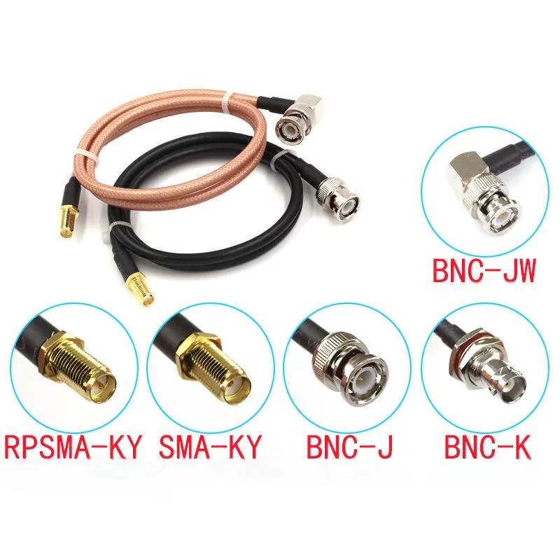
SMA and BNC connectors serve different purposes in wireless communication and testing. SMA connectors are ideal for high-frequency applications like WiFi, while BNC connectors are commonly used in video equipment and lab testing systems.
There are many RF cable connector types for terminating RF coax. The 5 most common types are Type N, UHF (PL-259/SO-239), TNC, BNC, and SMA . Each has its uses:
- Type N: Threaded, weatherproof, medium-size. Handles DC to ~11 GHz , used in telecom and test gear.
- UHF (PL-259/SO-239): Large threaded connector (standard on older VHF/UHF amateur gear), usable up to ~100 MHz.
- TNC: Threaded version of BNC; better VSWR at microwave frequencies.
- BNC: Bayonet locking miniature connector. Common in lab/test gear, CCTV and video up to ~2 GHz .
- SMA: Precision ½‑inch threaded connector, good for DC–18 GHz. Common on WiFi/LTE antennas and RF amplifiers .
Other connectors include F-type (screw-on for TV antenna/cable, used with 75Ω coax), RCA (phono) plugs for analog A/V, MCX/MMCX, 3.5mm, N-male/female, 7/16 DIN, etc. For example, RCA plugs (red/green/blue or red/white/yellow) are RF coax connectors used to carry analog audio/video signals – you can see a close-up of component video RCA connectors in the image above. No matter the type, the connector’s inner pin fits the cable’s center conductor and the outer shell contacts the cable shield, preserving the 50Ω or 75Ω line impedance .
When connecting cables, adapters like BNC-to-F or BNC-to-SMA are often used. Kits often include crimp-on or compression connectors; proper crimping tools and cable cutters/strippers are necessary to terminate cables reliably. For example, a dedicated RF crimping tool for RG-6/RG-59 crimps F-type or BNC connectors, and a coax cutter provides a clean, square cut on the cable end.
RF Cable Accessories and Tools
Working with RF cables often requires special accessories:
- Crimp/Compression Tools: To attach connectors (F-type, BNC, etc.) to coaxial cable. Crimp tools press ferrules tightly onto the cable. Compression tools (and boots) create a weatherproof seal.
- Cable Strippers and Cutters: For preparing cable ends. These tools peel back the jacket and shield without nicking the conductor.
- Extension Cables: Pre-made RF extension cords (often with F-type or BNC connectors) allow easy extension of a cable run. For example, TV antenna or satellite equipment often uses screw-on extension cables.
- RF Switches: Multi-way RF switches let you select between different antenna/cable sources. These are used in test setups or to switch TV antenna sources.
- Attenuators/Terminators: Precision resistive loads (e.g. 50Ω terminators) or pad attenuators can be added at the end of a cable to prevent reflections or reduce signal levels.
- Connectors and Adapters: Such as BNC-to-RCA, N-to-SMA, etc., to interface between different cable systems.
Signal Loss and Calculations
RF cables inevitably attenuate signals: the higher the frequency, the greater the loss per unit length. Detailed loss charts or calculators are used to estimate this. For example, one attenuation table shows that at 100 MHz, RG-58 (50Ω) has about 4.9 dB loss per 100 ft, whereas RG-6 (75Ω) has only 2.0 dB per 100 ft . At 1 GHz, RG-58 loses ~32.0 dB/100ft while RG-6 loses only ~6.1 dB . Thicker center conductors and better dielectrics (as in low-loss cable) dramatically reduce attenuation.
In practice, always account for cable loss in link budgets (antenna gain, cable loss, splitter loss). Online RF cable loss calculators let you input the cable type, length, and frequency to get a precise dB loss. Manufacturers like Belden or Times Microwave provide loss per length specifications for every cable type, and there are also general “RF cable loss charts” available as references.
Common Applications of RF Cables
RF cables are ubiquitous in broadcast and communications:
- Cable TV and Antennas: Homes use 75Ω coax (e.g. RG-6) to connect TVs to cable modems or rooftop antennas. The cable outlet (“RF Out”) on a TV or set-top box uses a threaded F-type connector. The TV coax input is designed to mate with an RF cable’s plug. As noted, “RF cables possess a single-pin connector compatible with the TV set’s RF input… with a threaded connector to secure it” . This is the classic “antenna cable” that delivers over-the-air or CATV signals to your TV.
- Radio Communications: Amateur radio, mobile radios, and base stations use 50Ω coax (with connectors like PL-259, N, SMA, etc.) to link transceivers and antennas. RF cables here handle HF/VHF/UHF signals, and quality cable (low loss) is critical for transmit power.
- Wireless Networking: In some cases, WiFi and cellular antennas use coax pigtails (often RG-316 or LMR-195 with SMA/TS9 connectors) to reach rooftop antennas or signal boosters.
- Test & Measurement: Labs use precision 50Ω coax jumpers (with SMA/BNC connectors) for equipment. The cables are often individually tested and labeled for low VSWR.
- Broadcast Studio: Professional video gear may use 75Ω coax with BNC connectors for SDI video and RF broadcast feeds.
- Satellite TV: Uses RG-6 (75Ω) with dual F-connectors (to feed LNBs).
- Adapters and Networking: Interesting applications like MoCA (Multimedia over Coax Alliance) use existing home coax to carry Ethernet signals; they use adapters to convert the cable into a data network.
Frequently Asked Questions
- (typically 20 kHz–300 GHz) along a shielded conductor .
- How is an RF cable different from a coaxial cable? In practice they’re the same thing. “RF cable” usually just means a coaxial cable used for radio-frequency signals. The cable’s design (shielded coax) is what enables RF transmission .
- Is an RF cable the same as an HDMI cable? No. HDMI is a digital A/V interface. RF coaxial cables carry modulated radio or analog broadcast signals, not raw digital HDMI data. HDMI uses a completely different cable and connector.
- Are all RF cables the same? No. RF cables vary in impedance (50Ω vs 75Ω), construction (solid vs foam dielectric), and shielding quality. Thicker cables and better materials yield lower loss . The connectors and jackets also vary (some are weatherproof for outdoor use). Always choose a cable rated for the frequencies and power levels of your application.
- What is RF cable used for? RF cables are used any time you need to carry radio or TV signals via wire. This includes TV antenna feeds, cable TV, radio transmitters, wireless routers to external antennas, satellite systems, and interconnecting RF test equipment.
Bonfon Office Building, Longgang District, Shenzhen City, Guangdong Province, China

A China-based OEM/ODM RF communications supplier
Table of Contents
Owning your OEM/ODM/Private Label for Electronic Devices andComponents is now easier than ever.
