
A cable can look perfectly normal on the bench and still be wrong for the job.
One common example is a short test jumper that gets copied into production. The sample is 300 mm long, lies straight between two instruments, and passes the first RF check. Production changes it to 2 meters because the equipment cabinet is larger. The connectors stay the same. The cable family stays the same. Yet the loss budget is no longer the same.
Another problem appears after installation. A stiff cable is pulled sideways to reach a panel connector. The connection works at first, but the rear termination now carries mechanical load that was never present during the bench test.
These are not unusual RF failures. They usually start much earlier, when an RF cable is specified as a connector-to-connector item instead of a complete transmission path.
Before selecting SMA, BNC, TNC, N-Type, RG316, RG58, or a lower-loss cable, define what the assembly actually has to do.
Which RF Signal Path Should Define Your Cable Configuration?
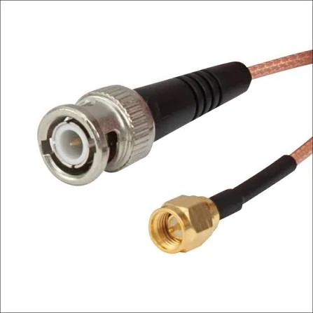
Close-up of a BNC to SMA RF coaxial cable assembly showing the two different connector interfaces and flexible braided coax cable. Suitable for RF equipment connections, test setups, antenna systems, and custom coaxial cable applications.
Start with the equipment. Not the cable catalog.
If the two fixed ports are already known, much of the configuration is decided before a cable model is discussed. A signal generator with an N female output and a fixture with an SMA female input does not simply need “an RF cable.” It needs a cable assembly with the correct mating connectors, impedance, frequency capability, routing length, and enough mechanical freedom to reach both ports without stressing them.
That sounds basic. It is still one of the easiest details to lose in an RFQ.
Identify the Fixed Equipment Ports First
Record both ends independently.
For Equipment A, note the connector family, gender, impedance, and mounting condition. Do the same for Equipment B.
That description leaves several questions open. Is the SMA side male or female? Is the TNC side standard or reverse polarity? Are both ports 50 ohms? Does either side need a right-angle connector because the enclosure is too shallow for a straight cable exit?
Now the supplier can actually check the assembly rather than guess from a product photo.
Polarity deserves the same attention. Standard SMA and RP-SMA parts can look close enough in online listings to create purchasing mistakes, especially when the description focuses on the threaded shell instead of the center contact.
The equipment port should decide the mating interface.
Do Not Treat a Test Jumper and an Antenna Feeder as the Same Product
A short cable between a spectrum analyzer and a test fixture has one set of priorities. A cable running from radio equipment to an outdoor antenna has another.
The test jumper may need frequent handling. Flexibility matters. Connector access matters. Repeatability after repeated mating may matter more than jacket weather resistance.
The antenna feeder may stay in place for years. Its total attenuation, outdoor routing, moisture protection, cable support, and connector sealing become much more important.
This is where buyers sometimes make a poor trade.
A small flexible coax looks convenient in a drawing, so the same cable is extended from 0.5 m to 5 m. Electrically, that change can be significant. At higher frequencies, the cable itself may become the main source of loss long before the connector reaches its rated frequency limit.
A larger low-loss cable solves part of that problem, but it creates another one: size.
Try routing a thick feeder through a compact enclosure and the mechanical issue becomes obvious. The cable may be electrically suitable and physically awkward.
That is why cable selection cannot be separated from installation.
Write Down Frequency, Impedance, and Length Before Choosing the Cable Family
A system operating only around 900 MHz places different demands on the cable than one operating near 5.8 GHz. If the same product covers several bands, use the highest required operating frequency when reviewing attenuation and connector capability.
Impedance also needs to be explicit.
Most RF communication assemblies are 50 ohms, while some video and broadcast systems use 75-ohm hardware. Similar connector names do not automatically mean identical electrical behavior.
Length is easy to underestimate because drawings make every cable look short.
For cable loss, 300 mm and 3 m are not small variations of the same assembly. They are different RF paths.
The actual attenuation should be taken from the cable manufacturer’s data at the required frequency. A single “dB per meter” number should not be reused across the entire operating range.
For readers comparing common coaxial families, the TEJTE RG cable guide covers the broader cable differences. At the assembly stage, the useful question is simpler: does this exact cable still meet the loss target at this exact length?
Map the Whole Path Before Releasing the RFQ
A quick signal-path sketch often prevents more mistakes than a long product description.
Add adapters if they are really part of the installed system.
Do not hide them.
An adapter inserted later in production adds another interface, another possible mismatch, and another mechanical joint. The drawing should reflect the path the customer will actually use, not the cleaner version originally tested on the bench.
How Do You Match SMA, BNC, TNC, and N-Type to the Equipment?
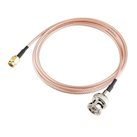
BNC male to SMA male RF cable assembly with flexible coaxial cable, designed for RF signal transmission between test instruments, wireless equipment, antennas, and other coaxial interfaces.
The front interface is usually dictated by the equipment, but the connector family still affects handling, size, retention, and cable choice.
SMA, BNC, TNC, and N-Type are not interchangeable answers to the same problem.
SMA Works Well Where Space Is Limited
SMA is common on compact RF modules, antennas, test fixtures, and microwave equipment.
The threaded coupling is useful where a small connector still needs a positive mechanical connection. For short equipment jumpers, SMA is often a natural fit.
The mistake is assuming that the SMA rating defines the whole assembly.
It does not.
An 18 GHz connector installed on a cable with unsuitable attenuation or poor termination does not create an 18 GHz cable assembly. The completed part has to be considered as one RF structure.
Rear geometry also matters. An SMA plug built for RG316 is not automatically the correct plug for RG58 just because both have an SMA male interface at the front.
The ferrule, cable entry, dielectric support, and center-contact termination are sized around the cable construction.
BNC Is Useful When Cables Are Changed Often
BNC is still common on laboratory instruments and test equipment because the bayonet coupling is quick to connect and remove.
That convenience is valuable on a bench where cables are changed repeatedly during debugging or measurement.
The purchasing trap is treating “BNC” as one universal electrical specification.
It is not.
Impedance version and actual frequency capability need to be checked for the specific connector and application. A familiar interface should not replace a datasheet check.
TNC Adds Threaded Retention
TNC is often selected when a threaded interface is preferred over BNC-style bayonet coupling.
That can be useful in industrial wireless equipment, antenna systems, or installations exposed to movement.
Threading helps keep the mating pair secured, but it does not fix bad cable routing. If a heavy cable hangs from the connector or is forced into a tight bend immediately behind it, the termination still sees stress.
N-Type Makes More Sense With Larger Cables and Field Connections
N-Type connectors are common on antenna equipment, base-station hardware, larger coaxial cables, and field-facing RF connections.
The interface gives more physical space for larger cable constructions and is generally easier to handle when the cable itself is substantial.
Still, an N-Type connector should not be called “outdoor ready” without checking the exact construction.
Sealing, jacket material, boot design, panel interface, and installation method decide whether the finished assembly can tolerate the environment.
One Final Check Before the Cable Goes Into Production
For each end, verify five items separately:
connector family, gender, polarity, impedance, cable termination.
Then check frequency and installed length at the assembly level.
A cable that mates is not automatically a cable that belongs in the system.
That distinction is small on the purchase order. It becomes much larger after 1,000 incorrect assemblies have already been built.
Which Coaxial Cable Construction Fits the Required RF Link?
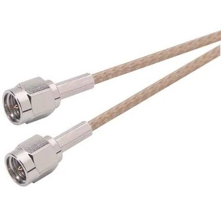
N-Type male to male coaxial cable assembly designed for RF signal transmission in antenna systems, communication equipment, base-station hardware, and other applications requiring a secure threaded RF connection.
Once both connector ends are fixed, cable choice becomes much easier to discuss.
But cable family names can still cause trouble.
A buyer may request RG316 because the previous assembly used RG316. That does not automatically mean every RG316 from every supplier has identical dimensions, shielding construction, attenuation, or jacket behavior. The connector rear body still has to fit the actual cable being used.
The front connector may mate perfectly while the rear termination is wrong.
That is a production problem, not a catalog problem.
Compare the Cable by Use, Not by Name Alone
RG174, RG316, RG58, and RG213 are often considered for very different reasons.
RG174 is small and easy to route where space is tight. RG316 is also relatively compact, but is commonly selected where temperature capability, RF use, and assembly flexibility make it more suitable than a basic miniature cable.
RG58 is physically larger and is widely used for general RF cable assemblies. RG213 moves much further toward the larger-cable side and is more practical where routing space is available and a heavier cable is acceptable.
The point is not to rank one above another.
They solve different mechanical and electrical problems.
| Cable family | Practical reason to consider it | Main point to check |
| RG174 | Tight routing space | Loss at required frequency and length |
| RG316 | Compact RF jumper | Exact connector rear geometry |
| RG58 | General equipment cable | Size, attenuation, termination |
| RG213 | Larger cable run | Bend space and connector support |
| LMR200 / 240 | Lower-loss routing where size still matters | Connector compatibility |
| LMR400 | Longer lower-loss runs | Cable stiffness, bend radius, connector load |
This table is a starting point rather than a substitution chart.
If the system already has a fixed loss limit, work backward from that number. A cable that is mechanically convenient may simply consume too much of the available RF budget.
Lower Loss Usually Costs You Something Mechanically
Longer links often push designers toward LMR-style low-loss cables or other larger coaxial constructions.
That makes sense electrically.
It can become awkward mechanically.
Take a compact enclosure with an SMA bulkhead connector. Replacing a small flexible cable with a much larger low-loss cable may reduce attenuation, but now the cable cannot make the same turn behind the panel. The connector body starts carrying the bending load.
The RF improvement may be real while the installation gets worse.
This is why cable diameter, bend radius, stiffness, and connector support belong in the same review as attenuation.
Do not wait until final assembly to discover that the selected cable only fits when it is forced against the enclosure wall.
Check the Connector Rear End Against the Actual Cable
Connector compatibility is more than a product title saying “for RG316” or “for RG58.”
Look at the dimensions that actually affect termination:
- cable outside diameter
- dielectric diameter
- center conductor
- braid or shield construction
- cable entry diameter
- ferrule size
- center-contact termination method
A ferrule that is too large may not compress the braid correctly. One that is too small can damage the jacket or make assembly inconsistent.
The center conductor matters as well.
Solid and stranded constructions do not always behave the same during soldering or crimping. An assembly process developed around one cable should not be transferred to a replacement cable only because the nominal family name looks similar.
For production orders, it is safer to lock the approved cable manufacturer and part number once the assembly has passed validation.
How Should Cable Length and Frequency Control the Loss Budget?
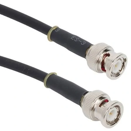
BNC male to male RF coaxial cable assembly featuring bayonet-style connectors and a flexible black coax cable. Commonly used with RF test instruments, measurement equipment, signal generators, and laboratory systems.
Cable loss should be calculated before the assembly is ordered, not after the finished cable fails the VNA test.
The difficult part is using the correct attenuation value.
Cable loss changes with frequency. A number taken from a lower-frequency datasheet point should not be reused blindly at the top of the system band.
Use the Frequency the System Actually Has to Pass
Suppose a cable is used across several wireless bands.
If the assembly works at 900 MHz but fails near the upper band, checking only the low-frequency loss tells you very little.
Use the attenuation value at or near the highest required operating frequency.
Then add the interfaces.
This is still only an estimate.
Connectors and adapters are not independent resistors that always add perfectly. Reflections, mismatch, termination quality, and the measurement reference plane affect the final result.
That is why the finished cable still needs an S21 check when insertion loss matters.
Shorter Is Not Always Better
A buyer may try to recover margin simply by shortening the cable.
Electrically, that often helps.
Mechanically, it can create a worse assembly.
A cable with almost no routing slack may pull on the connector after the enclosure is closed. It may also be bent more sharply because the installer has no room to form a relaxed path.
A few extra centimeters may cost a small amount of RF loss but prevent much larger mechanical problems.
The correct length is therefore not “as short as possible.”
It is the shortest length that still installs without excessive tension, bend, or connector loading.
When Should You Use a Flexible Cable Instead of a Rigid Adapter?
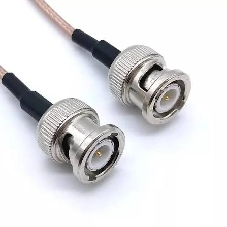
Flexible BNC to BNC coaxial jumper cable designed for RF test setups, laboratory instruments, measurement equipment, and general signal connections where cables may need to be connected and removed frequently.
A rigid adapter looks cleaner on a drawing.
Real equipment is not always that cooperative.
Ports may be offset by a few millimeters. Panel tolerances stack up. Two assemblies that appeared coaxial in CAD are slightly misaligned after production.
A short flexible RF cable can absorb that difference.
Use a Jumper Where Alignment Is Not Guaranteed
Flexible jumpers work well between equipment ports that do not sit on the same axis or where service access requires movement.
The cable acts as mechanical accommodation as well as an RF path.
That can be safer than forcing two rigid interfaces together.
This matters especially around PCB-mounted connectors. A small board connector should not be used as a structural support for a heavy adapter chain.
Semi-Rigid and Semi-Flexible Cable Need a Different Mindset
Semi-rigid cable is useful where the final geometry is controlled and repeatable.
Once formed, it can hold its routing very well.
That same advantage becomes a limitation if production tolerances or maintenance require frequent repositioning.
Semi-flexible constructions provide more routing freedom, but they still should not be treated like ordinary soft jumpers.
The mechanical requirement comes first: does the cable need to move, or does it need to stay exactly where it was formed?
Remove Adapters That Do Not Need to Be There
Adapter stacks often start as a temporary lab fix.
Then they quietly become part of production.
An SMA-to-BNC adapter, followed by another transition and then a cable, may solve a connection problem quickly. It also creates extra interfaces and extra mechanical joints.
If the configuration is stable, replacing unnecessary adapters with a cable assembly terminated directly in the required Connector A and Connector B is usually cleaner from both an RF and mechanical standpoint.
Before doing that, verify the final assembly rather than assuming fewer interfaces automatically means acceptable RF performance.
The finished cable is still the item that has to pass.
How Do Installation Conditions Change RF Cable Selection?
A cable can test well on an open bench and behave differently once it is installed.
The reason is often mechanical rather than mysterious RF behavior.
Inside real equipment, the cable may be tied to a harness, bent around a chassis wall, pulled toward a bulkhead connector, or compressed by a cover. None of those conditions exist when the same assembly lies straight on a test table.
Flexibility Is Not the Same as Flex Life
A soft cable is easy to bend by hand. That does not mean it is intended for continuous movement.
If the application falls into the third category, normal RF jumper construction should not automatically be treated as a flex-rated cable.
The same point applies near the connector.
Repeated bending immediately behind the termination can fatigue the braid, conductor, or strain-relief area long before the rest of the cable shows visible damage.
Outdoor Runs Need More Than an Outdoor-Looking Connector
For antenna installations, moisture is usually the first concern buyers mention.
It should not be the only one.
Check the cable jacket, UV exposure, connector sealing method, routing direction, and where water could collect. A sealed connector mounted correctly can still be part of a poor outdoor installation if water runs along the cable and enters through another weak point.
Cable support matters too.
Do not let a long feeder hang from the RF connector.
Check the Final Bend After Assembly
Minimum bend radius should come from the actual cable specification.
More importantly, inspect the cable after the equipment is fully assembled.
A route that looks comfortable with the enclosure open may become much tighter after a cover, bracket, or nearby PCB is installed.
That final condition is the one that matters.
How Can You Verify the Finished RF Cable Assembly?
Continuity is useful.
It is not an RF acceptance test.
A cable can pass center-conductor continuity and shield continuity while still showing poor return loss or excessive insertion loss at the target frequency.
Inspect the Terminations Before Connecting the VNA
Start with the parts that production can see.
Check the center contact position, dielectric condition, braid capture, ferrule, cable jacket, and strain relief.
A badly positioned center pin may create mating problems. Poor braid contact can affect shielding and impedance. Excessive soldering heat can damage the dielectric even when the cable still passes a basic DC check.
Visual inspection does not prove RF performance, but it can remove obvious failures before test time is wasted.
Use Continuity and Isolation as the First Electrical Gate
The center conductor should connect end to end.
The shield should connect end to end.
Center and shield should remain isolated.
If the assembly fails here, there is no reason to move directly to RF measurement.
If it passes, the RF work has only started.
Sweep the Band That the Assembly Will Actually Use
For assemblies with defined RF requirements, S11 and S21 measurements are more useful than a single spot check.
S11 can reveal mismatch behavior.
S21 shows transmission loss through the complete cable assembly.
The sweep should cover the intended operating band, not just an easier lower-frequency point.
For mechanically sensitive projects, there is another useful test: measure the assembly once on the bench and again after installation.
If the result changes noticeably after routing, the problem may be related to bend, strain, connector loading, or installation geometry.
Do not apply one universal VSWR or insertion-loss limit to every cable.
Acceptance limits should come from the application.
How Can You Build an RF Cable Selection Matrix?
A practical RF cable review works better when electrical and mechanical checks sit in the same place.
The table below can be used as an early design screen.
| Application | Cable concern | Connector options | Main design priority |
| RF test bench | Flexible, repeatable handling | SMA / SMA, SMA / BNC | Measurement consistency |
| Industrial wireless unit | Mechanical retention | TNC / TNC, TNC / SMA | Strain relief |
| Outdoor antenna feeder | Lower loss, weather exposure | N / N, N / SMA | Attenuation and sealing |
| Compact RF module | Small cable diameter | SMA / SMA | Routing space |
| Instrument connection | Frequent access | BNC / BNC, BNC / SMA | Interface fit |
| Custom equipment jumper | Application-specific | Mixed interfaces | Complete assembly validation |
These are candidate combinations, not fixed rules.
The final choice still has to pass frequency, impedance, cable geometry, installation, and RF test requirements.
How Should Buyers Specify a Custom RF Cable Assembly?
A custom RF cable RFQ should remove guesswork.
“50-ohm RF cable, 1 meter” is not enough.
Both ends need to be defined independently.
Length should also be defined clearly.
Does 500 mm mean connector tip to connector tip, cable jacket length, or another reference dimension?
That small detail causes real disputes in custom production.
For new assemblies, first-article approval is usually worth the time. Approve the drawing, dimensions, cable model, connector part numbers, termination process, and RF result before releasing a large order.
Once approved, control substitutions.
A supplier changing the cable, ferrule, center contact, or connector rear body may produce an assembly that looks nearly identical but does not behave the same.
The BOM should lock the version that was actually qualified.
FAQ
Can a cable pass continuity and still fail RF testing?
Yes. Continuity checks for basic electrical connection. It does not confirm impedance control, return loss, VSWR, or insertion loss at RF frequencies.
Does a higher-frequency connector make the whole cable assembly higher frequency?
No. The cable, connector termination, length, adapters, and assembly quality can become the limiting factors before the connector rating is reached.
Should I always use the lowest-loss cable available?
Not necessarily. Lower-loss cables are often larger and stiffer.
Can I replace RG316 with another 50-ohm cable?
Only after checking dimensions, attenuation, shielding, connector compatibility, and the finished assembly result. Matching impedance alone is not enough.
Should custom RF cable assemblies be tested before mass production?
For applications with defined RF limits, first-article testing is a sensible step.