
How Does an RF Adapter Solve Connector Compatibility Problems?
A cable assembly can pass a continuity test and still be the wrong RF connection.
This situation appears often during prototype testing and equipment integration. The connector threads match, the cable can be screwed into place, and the signal seems normal at low frequency. The problem only appears when the system moves closer to its actual operating range.
An RF adapter is usually introduced to solve this type of interface mismatch. It allows engineers to connect two different connector standards without redesigning the entire RF path. A test engineer may need an SMA interface connected to a 2.92mm port. A communication system may require an N Type antenna interface connected to equipment using SMA. A laboratory setup may combine BNC instruments with coaxial components using different interfaces.
The adapter looks simple from the outside, but the internal requirements are not simple. A usable RF adapter must satisfy both mechanical connection and electrical requirements.
Why Do RF Systems Need Interface Conversion?
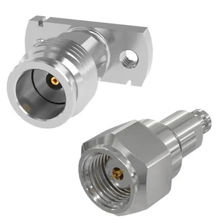
SMA RF adapters are widely used for connecting RF modules, antennas, cables, and test equipment with different connector configurations. They provide flexible interface conversion while maintaining 50 ohm impedance compatibility for many RF applications.
RF equipment rarely uses only one connector family throughout an entire development cycle.
A wireless module may use a compact SMA interface during development. The final antenna system may use an N Type connector for outdoor installation. Laboratory equipment may rely on BNC interfaces because they are convenient for frequent connection and disconnection. Microwave measurement systems may require higher-frequency interfaces such as 2.92mm or 3.5mm connectors.
The adapter becomes the transition point between these different standards.
Typical RF adapter applications include:
| Application Scenario | Common Conversion Requirement | Example Adapter |
| RF module testing | Small connector to test equipment interface | SMA to BNC adapter |
| Antenna installation | Equipment port to outdoor antenna connector | SMA to N Type adapter |
| Prototype development | Temporary interface conversion | SMA female to SMA male adapter |
| Microwave measurement | Precision connector transition | SMA to 2.92mm adapter |
| Legacy equipment connection | Older connector systems integration | UHF adapter |
The purpose is not only to make two connectors physically connect. The RF signal must continue through the transition with acceptable electrical characteristics.
A poorly selected adapter may create a connection that works mechanically but introduces problems into the RF path.
Why Are RF Adapters More Than Mechanical Converters?
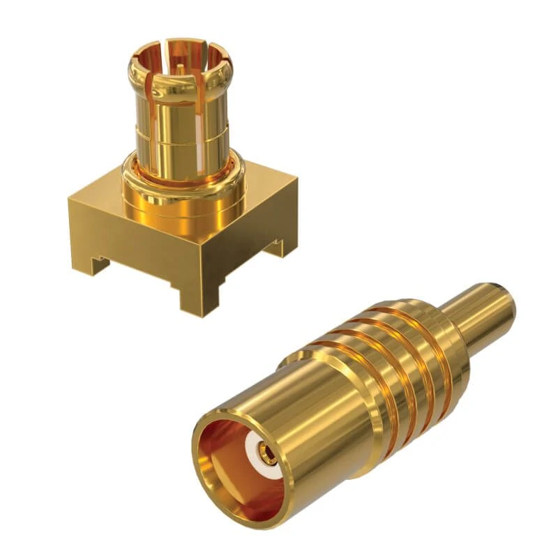
High precision RF adapters are manufactured with accurate mechanical dimensions and optimized internal structures to support high-frequency signal transmission. These microwave adapters are suitable for RF test equipment, measurement systems, communication modules, and applications requiring low signal loss and stable impedance matching.
Many purchasing mistakes happen because buyers select adapters only by connector appearance.
Two adapters may look almost identical in a product image but have completely different electrical specifications. A connector body, thread size, and interface shape do not determine the complete RF performance.
Before selecting an RF adapter, engineers normally need to confirm several factors:
- Connector interface type
- Male or female configuration
- Impedance
- Frequency range
- VSWR requirement
- Insertion loss
- Application environment
For example, an SMA adapter used for a low-frequency control signal and an SMA adapter used in a microwave measurement setup may have completely different requirements.
A general-purpose RF connector adapter may be acceptable for equipment interconnection. A precision microwave adapter requires tighter mechanical tolerances, better interface alignment, and more careful inspection.
Where Do RF Adapters Appear in an RF Signal Chain?
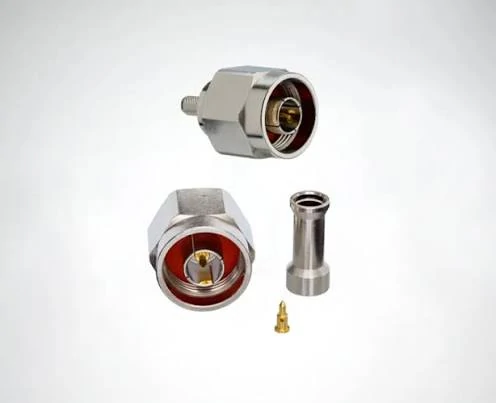
This RF adapter is designed for connector interface conversion in RF systems. It provides a reliable transition between different coaxial connector standards while maintaining proper mechanical connection and signal transmission performance. RF adapters are commonly used in antenna systems, communication equipment, RF testing setups, and microwave applications.
A prototype setup may benefit from adapter flexibility. A permanent installation may be better served by a customized cable assembly with the correct connector combination from the beginning.
How Do You Choose the Correct RF Adapter Interface?
The first step is not selecting a product model. It is identifying the two interfaces that need to be connected.
An RF adapter specification should start with:
Connector A → Connector B
For example:
- SMA male to N female
- BNC male to SMA female
- SMA female to 3.5mm male
- N male to 2.92mm female
This basic information prevents one of the most common purchasing errors: selecting an adapter with the correct connector family but the wrong gender or polarity.
Match the Adapter According to Connector Standards
Different RF connector families were developed for different application requirements.
| Connector Family | Typical Application | Adapter Examples |
| SMA | RF modules, antennas, test equipment | SMA adapter, SMA to N adapter |
| BNC | Laboratory instruments, quick connection systems | BNC adapter |
| N Type | Outdoor antenna and communication systems | N Type adapter |
| TNC | Threaded versions of BNC applications | TNC adapter |
| UHF | Legacy radio equipment | UHF adapter |
| 2.92mm / 3.5mm | Microwave measurement | Microwave adapter |
A common conversion requirement is SMA to N Type.
This is frequently used when a compact RF module needs to connect with a larger coaxial antenna system.
How Does Impedance Affect RF Adapter Selection?
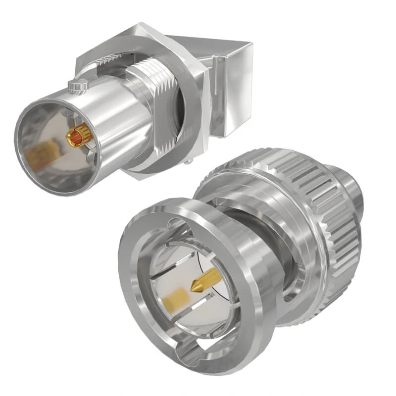
BNC RF adapters are frequently used in laboratory instruments, signal testing equipment, and prototype verification systems. They allow connection between BNC interfaces and other RF connector standards while providing quick installation and reliable signal transmission.
An RF adapter can fit perfectly and still create problems inside the signal path.
One of the first specifications engineers should confirm is impedance. Most RF systems use 50Ω impedance, especially communication equipment, antennas, RF modules, and microwave test systems. The connector, adapter, cable, and equipment port should normally maintain the same impedance throughout the complete RF path.
If one component introduces an impedance mismatch, part of the signal energy can reflect back toward the source. The result may appear as:
- Increased VSWR
- Higher return loss
- Additional insertion loss
- Reduced measurement accuracy
- Unstable system performance
This is why selecting a coax adapter is not only about finding a mechanical conversion.
Keep the Entire RF Path at the Same Impedance
A common mistake in purchasing is checking only the adapter interface while ignoring the rest of the RF chain.
For example, an engineer may select an SMA to BNC adapter because both connectors are available, but the application requires a 50Ω connection. If the BNC side is designed for a 75Ω video system, the connection may physically work but create electrical problems.
Before ordering an RF adapter, confirm:
| Parameter | Check Requirement |
| Connector Type | SMA / BNC / N Type / TNC / Microwave interface |
| Impedance | 50Ω or 75Ω |
| Frequency Range | Must cover operating frequency |
| VSWR | Match system requirement |
| Application | Test, antenna, communication, or module |
A coax adapter should be treated as part of the RF transmission line, not as a simple mechanical accessory.
Why Should You Avoid Mixing 50Ω and 75Ω RF Adapters?
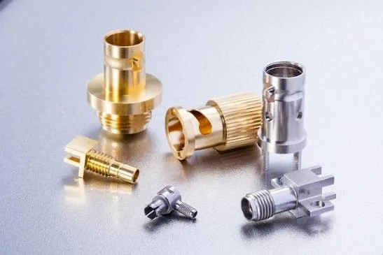
RF coaxial adapter components include different connector interfaces, mounting structures, and mechanical designs for various RF applications. Customized adapter solutions can support different connector combinations, cable assemblies, testing equipment, and communication systems.
Some connector families are available in both 50Ω and 75Ω versions.
The external appearance can sometimes be similar, especially for inexperienced buyers. The difference is usually related to internal geometry, including:
- Center contact dimensions
- Dielectric structure
- Connector interface design
A connection between mismatched impedance systems may still pass a basic continuity test.
This creates a common field issue:
The assembly works during initial installation, but the measured RF performance is worse than expected.
For low-frequency applications, the problem may not be obvious. At higher frequencies, the impact becomes easier to detect because small impedance changes can create larger reflection problems.
Check RF Specifications Instead of Selecting Adapters by Appearance
Product photos are useful for identifying connector shape, but they cannot confirm electrical compatibility.
A complete RF adapter specification should include:
- Connector gender
- Impedance
- Frequency rating
- VSWR specification
- Insertion loss
- Material and plating
- Mounting style
For example, two SMA adapters may both look like standard SMA products, but one may be intended for general RF connections while another is manufactured for microwave testing.
The difference may come from:
- Tighter machining tolerance
- Better center pin alignment
- Improved dielectric control
- Higher-frequency design requirements
For normal equipment connection, a standard adapter may be sufficient. For VNA calibration or microwave measurement, the adapter specification needs much closer attention.
How Should You Select Adapter Gender and Mounting Style?
Connector gender is one of the simplest specifications, but it causes many ordering errors.
Before selecting an RF adapter, confirm:
- Which side is male?
- Which side is female?
- Is the interface standard polarity?
- Does the equipment port match the adapter direction?
A connector that physically threads together does not always mean it is the correct configuration.
Identify Male and Female Interfaces Before Ordering
RF connector gender is determined by the contact structure.
Generally:
- Male connector → center pin
- Female connector → socket/contact receptacle
However, some RF families have reverse polarity versions, especially in wireless networking applications.
A buyer should not rely only on connector appearance. The correct description should specify both sides clearly.
Examples:
- SMA male to N female adapter
- SMA female to BNC male adapter
- N male to SMA female adapter
This prevents receiving an adapter with the correct connector family but the wrong mating direction.
Match Cable-End Adapters With Equipment Ports
Adapter selection becomes more complicated when cables are already installed.
Common mistakes include:
| Problem | Result |
| SMA male connected to SMA male requirement mismatch | Cannot mate correctly |
| Wrong N Type gender selected | Installation failure |
| Incorrect polarity | Signal path mismatch |
| Wrong mounting style | Mechanical interference |
For cable assemblies, the adapter should also consider:
- Cable diameter
- Bend radius
- Mechanical stress
- Installation space
A small adapter attached to a heavy coax cable may experience additional mechanical force during installation.
Consider Bulkhead and Panel Mounting Requirements
Some RF adapters are not designed only for cable-to-cable connection.
Panel mount and bulkhead versions are commonly used in:
- Equipment enclosures
- RF test fixtures
- Communication cabinets
- Antenna panels
These adapters usually include mounting features such as:
- Threaded body
- Mounting nut
- Flange holes
- Sealing structure
When used outdoors or in enclosed equipment, mechanical installation becomes part of RF reliability. A loose mounting interface can create stress on the connector and cable assembly.
RF Adapter Interface Selection Matrix
This table helps match common application requirements with suitable adapter categories.
| Requirement | Recommended Adapter | Main Consideration |
| RF module connection | SMA Adapter | Compact size and board compatibility |
| Outdoor antenna transition | N Type Adapter | Environmental durability |
| Oscilloscope/test equipment | BNC Adapter | Quick connection requirement |
| Microwave measurement | 2.92mm / 3.5mm Adapter | Frequency capability and precision |
| Legacy radio equipment | UHF Adapter | Existing equipment compatibility |
| High-frequency precision test | Microwave Adapter | VSWR and machining tolerance |
The best adapter choice depends on the complete RF system rather than the connector name alone.
A practical specification should always describe the connection requirement, operating frequency, impedance, and installation environment together.
How Do SMA, BNC, N Type, and Microwave Adapters Differ in Real Applications?
A connector conversion that works on a drawing may still fail during actual integration.
This happens because RF adapters are often selected during the early design stage, when engineers only know the interface requirement. Later, the application changes. The cable becomes longer, the operating frequency increases, or the equipment moves from a laboratory environment into field installation.
At that point, the adapter is no longer just a connection accessory. It becomes part of the RF transmission path.
Different adapter families solve different problems. SMA, BNC, N Type, and microwave adapters may all convert interfaces, but they are designed around different mechanical and electrical requirements.
When Does an SMA Adapter Become the Practical Choice?
During sourcing, engineers usually need to confirm:
- Is the adapter 50Ω?
- Does the frequency rating cover the application?
- Is the cable side compatible?
The same adapter type may not be the best option for a precision microwave test cable where repeatability is more important.
The interface is only one part of the RF path.
Why Are BNC Adapters Still Used in RF Test Environments?
BNC connectors are not usually selected because they offer the highest frequency capability.
They remain popular because engineers value speed during repeated testing.
A technician working with oscilloscopes, signal generators, or laboratory instruments may connect and disconnect cables many times during a development cycle. A threaded connector would slow down this process.
BNC adapters are commonly used in:
- Laboratory test benches
- Signal measurement equipment
- Prototype verification
The important point is that BNC convenience does not remove the need for specification checking.
Before using a BNC adapter, confirm:
- 50Ω or 75Ω version
- Required frequency range
- Measurement accuracy requirement
A BNC adapter used for a general signal connection and one used in a calibrated RF measurement environment should not be treated as the same component.
Where Does an N Type Adapter Fit Better Than Smaller RF Interfaces?
N Type adapters are often chosen when mechanical durability matters.If the mounting structure is not considered, the RF interface may become unstable over time.
How Should You Decide Between an RF Adapter and a Custom Cable Assembly?
This decision usually depends on whether the connection is temporary or permanent.
An adapter is useful when the engineer expects the system configuration to change.
A cable assembly is usually better when the final installation has already been defined.
Use RF Adapters During Development and Testing
During prototype stages, requirements often change.
A laboratory may keep several conversion options available:
- SMA to BNC
- SMA to N Type
- SMA to 2.92mm
- N Type to SMA
This reduces the need to rebuild cables every time the equipment changes.
The limitation is that every adapter introduces another interface.
More interfaces mean more points that require attention:
- Additional insertion loss
- Possible impedance discontinuity
- More mechanical connections
- Higher assembly complexity
For short-term testing, this trade-off is acceptable.
Replace Multiple Adapters With a Direct Cable Assembly When the Design Is Fixed
A production system usually benefits from reducing unnecessary transitions.
The second option removes two extra interfaces.
For OEM applications, a supplier should receive complete requirements:
| Requirement | Example |
| Connector A | SMA Female |
| Connector B | N Male |
| Cable Type | RG316 / RG174 / Low Loss Cable |
| Length | 500 mm |
| Impedance | 50Ω |
| Frequency | DC–6 GHz |
| Environment | Indoor / Outdoor |
A complete specification helps avoid replacing parts after production has started.
How Do RF Adapters Influence Measurement Results?
In low-frequency applications, adapter influence may not always be obvious.
In higher-frequency measurement, the effect becomes easier to see.
A VNA measurement can reveal differences caused by:
- Interface mismatch
- Connector wear
- Poor alignment
- Excessive adapter stacking
Important parameters include:
- VSWR
- Return loss
- Insertion loss
- S-parameters
One common misunderstanding is that a continuity test proves the adapter is acceptable.
RF Adapter Validation Record for Engineering Use
| Item | Record |
| Adapter Model | Actual part number |
| Interface Combination | SMA/N/BNC/Microwave |
| Gender | Male/Female |
| Impedance | 50Ω |
| Frequency Range | Operating band |
| VSWR | Test result |
| Insertion Loss | Test result |
| Test Equipment | VNA / Analyzer |
| Inspection Date | Date |
| Status | Approved / Rejected |
This type of record is especially useful when multiple suppliers provide similar-looking adapters.
FAQ
Why does an RF adapter fit the connector but still fail in the actual application?
A mechanical match only confirms that the two connectors can be assembled together. It does not confirm that the RF path is suitable.
This problem is often seen when an adapter is selected from a product photo or connector name only. The interface may be correct, but the impedance, frequency range, or internal structure may not match the system.
For instance, an SMA adapter used in a low-frequency module test may work normally, while the same type of adapter may show unstable results in a higher-frequency measurement setup. The difference is usually related to RF characteristics rather than the external connector shape.
What should be checked before replacing a cable with an RF adapter?
The first thing to check is whether the adapter is solving a temporary connection problem or becoming part of the final RF path.
For laboratory testing, an RF adapter is often a convenient choice because equipment with different connector standards can be connected quickly.
The extra connection point can increase assembly complexity and introduce another variable during production.
A supplier normally needs information such as:
- Connector A and Connector B
- Cable type
- Operating frequency
- Impedance
- Installation environment
Without these details, it is easy to select an adapter that works on the bench but is unsuitable for the final application.
Can an SMA adapter be connected directly to an N Type antenna system?
Yes, this is a common RF conversion requirement, but the adapter selection depends on the complete system.
The adapter only changes the interface. It does not improve the limitation of the cable, antenna, or equipment connected on either side.
Why does VSWR become worse after adding an RF adapter?
When an RF adapter is added, the signal passes through another mechanical transition.
If the adapter is not matched correctly with the cable and equipment, part of the RF energy can be reflected back.
How many RF adapters can be used in one RF connection path?
There is no universal number because the acceptable amount depends on the application.
A development engineer may use several adapters while comparing different instruments or modules. In this situation, flexibility is usually more important than minimizing connection points.
A production assembly has different requirements.In precision RF systems, engineers usually reduce unnecessary adapter combinations and keep the signal path as direct as possible.
