We share everything about Electronic Components OEM, ODM, or private label solutions...

We continuously share and publish original articles about electronic components and OEM/ODM/private label solutions. We hope these articles provide you with valuable insights to support your private label electronic components business.

If you don’t want to miss our article, please subscribe to our newsletter. 

Deployment diagram of an SMA male to N male cable connecting a cellular router indoors to an N-type antenna on a cell tower outdoors.

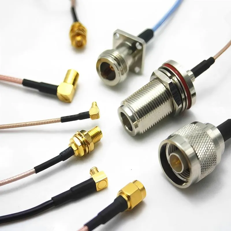
SMA to N Cable Guide for Outdoor Antennas and RF Feedlines

In most RF projects, the SMA to N cable doesn’t show up on the first schematic. Engineers usually start with the radio, the antenna, and the enclosure. Only later—often when the hardware is already built—does the mismatch become obvious: the device speaks SMA, while the rooftop hardware expects N-type.

Photograph showing a problematic chain of multiple adapters connected in series.

SMA to BNC Adapter Selection Guide for RF Labs

In RF labs and radio projects, interface problems almost never announce themselves clearly. Signals still pass. Instruments still lock. Measurements look “reasonable enough” to move forward. Then someone touches the cable, rotates the adapter slightly, or swaps instruments—and the numbers shift.

Close-up photograph of an SMA female to BNC male adapter.

BNC Cable Selection Guide for Video, CCTV, and RF Test

In most systems, the bnc cable is never the first thing specified. Engineers focus on the camera model, the recorder, the test instrument, or the RF module. The cable is added later, often pulled from whatever inventory already exists. On paper, that makes sense. In practice, it’s where margins quietly disappear.

SMA cable connecting a test instrument to an attenuator.

SMA Cable Selection Guide for RF and Antenna Systems

In RF systems, failures rarely announce themselves clearly. The radio powers up. The antenna is connected. The link works—at least at first. Then range feels inconsistent. Higher data rates drop sooner than expected. Small changes in routing suddenly matter.

Comparison chart of RG316 against other RG cable types (RG174, RG58, RG405, etc.)

RG316 Cable Internal Routing & High-Temperature Reliability

In most hardware projects, RG316 cable is not selected because it is optimal. It is selected because it fits. The enclosure is already constrained, the RF path is already defined, and something flexible is needed to connect two fixed points. RG316 is thin enough, heat resistant enough, and familiar enough, so it gets used.

Collection image of RG316 jumpers with various connector types

RG316 Coax Cable Jumpers: Length & Loss

RG316 coax cable jumpers rarely get much attention during early design reviews. They’re small, flexible, inexpensive, and usually added after the radio, antenna, and enclosure already feel “locked in.” That timing is exactly why they cause trouble later.

Illustration of a Wi-Fi Antenna Cable

WiFi Antenna Cable: Extension Length, Loss & End-Type Pairing

A wifi antenna cable rarely feels like a decision that deserves serious discussion. It is passive, inexpensive, and almost always added late in the design cycle—after the radio module is chosen, the enclosure is finalized, and the antenna location already looks “good enough.” That timing is precisely why antenna cable problems tend to surface only after deployment rather than during early testing.

Performance tier chart for antenna extension cables of different lengths at 5/6 GHz bands

SMA Bulkhead Cutout, Thread Length & Sealing Guide

An SMA bulkhead connector almost never looks like a failure point during design review. It’s small, passive, familiar, and usually selected after the enclosure shape and antenna choice already feel “locked.” That’s exactly why it causes trouble later. In real products, bulkhead issues rarely announce themselves with dramatic failures. Instead, they show up as small, expensive annoyances: a connector that slowly loosens, a seal that passes lab testing but leaks after a season outdoors, or a radio link that looks fine on paper yet behaves unpredictably in the field. None of these problems come from advanced RF theory. They come from mechanical assumptions that were never written down.

Illustration of a Logic Level MOSFET

Logic Level MOSFET Design for 3.3V and 5V Loads

A logic level MOSFET almost never feels like a decision worth debating. It’s small, inexpensive, and familiar. In most designs, it gets dropped in late—after the MCU pinout is fixed and the power rails already feel “good enough.”