We share everything about Electronic Components OEM, ODM, or private label solutions...

We continuously share and publish original articles about electronic components and OEM/ODM/private label solutions. We hope these articles provide you with valuable insights to support your private label electronic components business.

If you don’t want to miss our article, please subscribe to our newsletter. 

Schematic summarizing how various decision factors in extension cable selection (connector, length, bulkhead, routing) interact with each other.

WiFi Antenna Extension Cable: Length Loss & Connector Matching

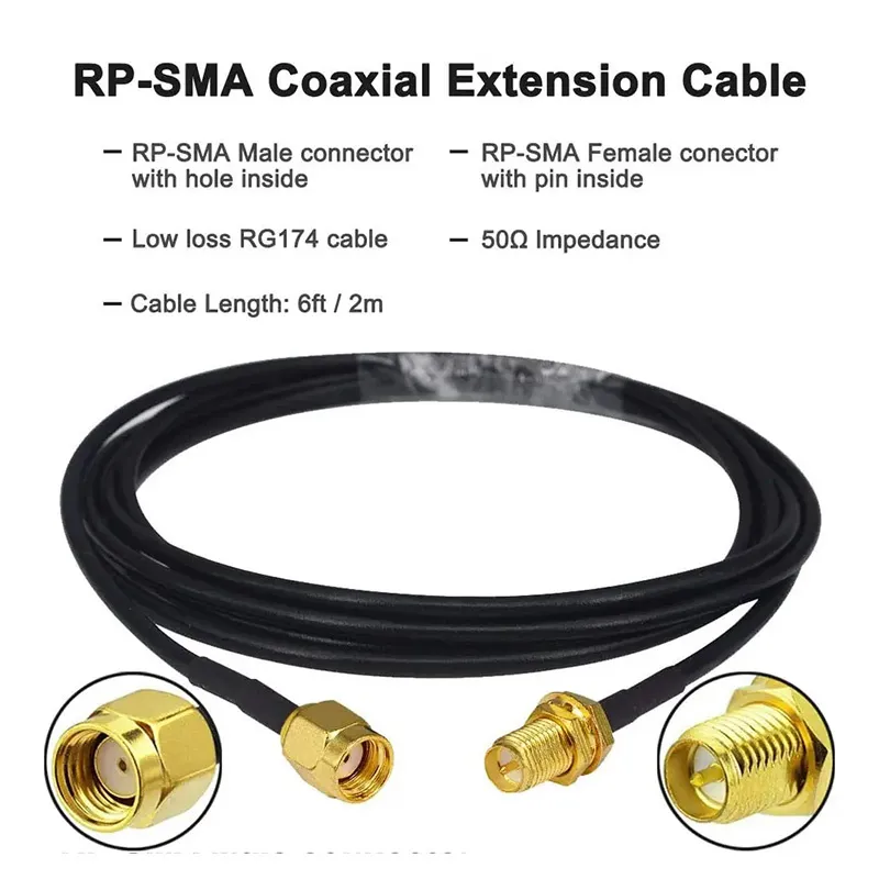
A wifi antenna extension cable almost never looks like the source of a weak wireless link. It’s passive, inexpensive, and usually added late in a project—often after the enclosure, antenna choice, and even regulatory planning already feel “finished.” In real Wi-Fi systems, especially at 5 GHz and 6 GHz, that last-minute extension often decides whether a link feels stable or quietly fragile. Nothing fails outright. Instead, higher MCS rates drop first, roaming becomes inconsistent, and coverage shrinks just enough to frustrate users without pointing clearly to the cause.

Close-up showing the physical characteristics and possible labeling of an antenna port on a Wi-Fi router or access point.

SMA Connector Identification, Bulkhead & Extension Guide

An SMA connector almost never looks like the cause of a weak wireless link. It’s small, passive, inexpensive, and usually added late in the build. Yet in real Wi-Fi and IoT systems, many performance problems trace back to the connector layer—specifically, misidentifying SMA vs RP-SMA, choosing the wrong bulkhead thread length, or extending the antenna path without accounting for loss and reflections.

Detailed structural diagram of a Female SMA Bulkhead Connector, showing threads, insulator, and other components.

RP-SMA Connector: Router ID, Matching & Extension Guide

Wireless systems rarely fail because someone misunderstood RF theory. Much more often, they fail because a small assumption slipped through late in the build. A connector that looked right. A cable that threaded on smoothly. An extension added after the enclosure layout changed.

Diagram illustrating the hidden impact of SMA antenna cable mismatches or arbitrary extensions on the stability of Wi-Fi/IoT systems, especially at 5GHz/6GHz bands.

SMA Antenna Cable Matching, Length & Panel Mounting Guide

A sma antenna cable rarely looks like a design risk. It’s passive, inexpensive, and usually added late in a build—sometimes after the enclosure, the antenna, and even the compliance plan are already “done.” Yet in real Wi-Fi and IoT systems, especially at 5 GHz and 6 GHz, that short coax run often decides whether a device feels stable or annoyingly fragile.

A product illustration of an RP-SMA coaxial extension cable, labeled with connector types (male with inner hole, female with inner pin), cable type (low loss RG174), impedance (50Ω), and length (6ft / 2m).

RP-SMA Antenna Guide: Router Matching, Gain & Extension

Routers and access points rarely fail because RF theory was misunderstood. Much more often, they fail because something small was assumed. A connector that looked right. An antenna that screwed on without resistance. A short extension added at the last minute because the enclosure layout changed.

A physical product photo of a Schottky diode in SOD-323F package (e.g., BAT46WJ), featuring its package size and cathode marking.

Schottky Diode Practical Applications and Design Guide

A schottky diode usually doesn’t get much attention when a circuit is first sketched. It sits quietly near a connector, a regulator, or a signal pin, looking interchangeable with half a dozen other diodes in the parts drawer. Yet in finished hardware, these parts often end up deciding whether a product behaves politely—or spends its life flirting with edge cases.

A diagram about the co-layout of SOD-323F package diodes and QFN package devices on a PCB, emphasizing current return paths and thermal design.

Reverse Polarity Protection Circuit Design Guide

Reverse polarity damage rarely makes a scene. Most of the time, nothing dramatic happens—no sparks, no smoke. A connector gets flipped, power flows the wrong way for a fraction of a second, and a board that looked perfectly healthy moments earlier is suddenly beyond repair.

A product portfolio showcase graphic from TEJIATE, likely featuring various reverse polarity protection solutions such as diodes in different packages, MOSFETs, and evaluation boards.

Reverse Polarity Protection Diode Design Guide

Preface Reverse-polarity damage rarely makes headlines, yet it’s one of the quietest ways to ruin a board. We’ve seen prototype runs fail simply because someone swapped a barrel connector during testing. Once current flows backward, even a small sensor node can destroy its microcontroller in a second.