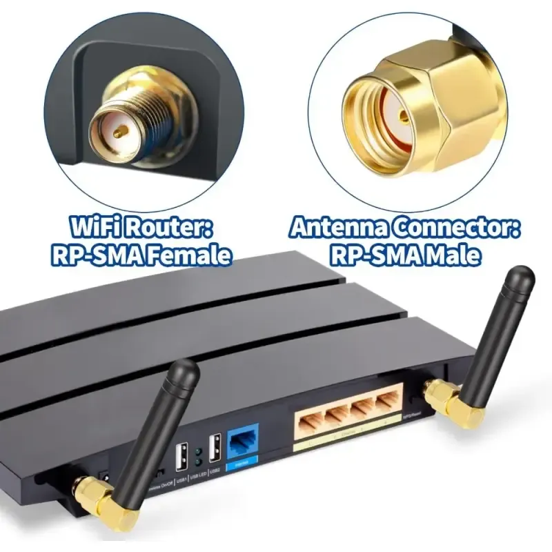
We share everything about Electronic Components OEM, ODM, or private label solutions...

We continuously share and publish original articles about electronic components and OEM/ODM/private label solutions. We hope these articles provide you with valuable insights to support your private label electronic components business.

If you don’t want to miss our article, please subscribe to our newsletter. 

Macro photo of TEJTE SOT-23 and SOD-323 packaged TVS array modules on a PCB.

ESD Protection Diode: High-Speed Interface Practice & Layout

Introduction — Why ESD Design Still Fails at High-Speed Ports Even after decades of ESD design guides and layout notes, it’s still surprisingly easy to damage a high-speed interface with the wrong ESD protection diode.What used to work for slow GPIO lines often collapses when the data rate hits several gigabits per second. A misplaced via or an oversized TVS diode array can distort the signal eye or fail IEC 61000-4-2 testing before you even finish your prototype.In real-world projects, I’ve seen engineers install a unidirectional TVS on an HDMI port simply because “the breakdown voltage looked right.”On paper, it made sense — but on the oscilloscope, half the signal swing disappeared.

Context diagram for feeder cable selection (likely showing application scenarios for long feeders vs. short jumpers).

Outdoor Mast Mount Antenna Guide: Brackets & IP Ratings

In every outdoor deployment, a mast-mount antenna defines whether your network keeps its link stable through wind, rain, and heat. The correct mix of antenna type, bracket design, and mounting hardware determines not just RF reach but mechanical integrity. For context, TEJTE’s Wi-Fi Antenna Guide explains how 2.4 GHz and 5 GHz patterns behave when antenna height and orientation change—an insight that directly applies to mast setups.

Diagram of a wireless 2.4 GHz RF transceiver module with an SMA antenna interface

Ground Clearance Antenna Layout & 2.4 GHz Rules

Introduction — Why Ground Clearance Decides Antenna Success In every compact 2.4 GHz IoT device, the ground clearance beneath the antenna defines whether the signal travels cleanly or fades halfway across the room. As detailed in TEJTE’s Wi-Fi Antenna Guide, return-current paths and dielectric spacing have as much influence as gain numbers.

FPC Antenna Product with Spacing Illustration Photo

FPC Antenna Guide: 2.4 GHz Layout & Tuning for IoT

When you’re designing a compact Wi-Fi or IoT board, the performance of an FPC antenna quietly decides whether your signal remains solid or fades after a few meters. Layout isn’t just about sticking a flexible patch—it’s about geometry, grounding, adhesive strength, and cable routing.

Product photo of a U.FL (IPX) to SMA pigtail cable

Outdoor Omni Antenna Selection & Ordering Guide

Choosing the right outdoor omni antenna defines whether your Wi-Fi or IoT deployment thrives or struggles against wind, rain, and cable loss. This guide walks engineers and buyers through the complete process — from class selection and weatherproof validation to cable management, placement, and final purchase order (PO) requirements.

Product photo of a rubber duck antenna with a foldable or bendable whip section

Rubber Duck Antenna Selection & Ordering Guide

When engineers talk about compact Wi-Fi or IoT builds, the rubber duck antenna is often the first image that comes to mind — that stubby black whip you see on routers, handheld sensors, or gateway nodes. You’ll find it standing on Wi-Fi routers, IoT gateways, handheld scanners, or even custom telemetry boards scattered across any modern lab bench. It’s small, durable, and oddly familiar — the sort of part that just works until you pick the wrong one.

Diagram of a U.FL to SMA pigtail cable

Omnidirectional Antenna Selection & Ordering Guide

In every Wi-Fi or IoT deployment, the humble omnidirectional antenna quietly defines whether your signal holds steady or drops off after a few meters. It’s what allows your 2.4 GHz nodes to talk seamlessly across walls, plastic housings, or rooftops. But selecting one isn’t about choosing “2 dBi or 5 dBi.” It’s a series of small but critical engineering calls — antenna form, connector, gain, cable type, and how all these fit your housing and PCB.

Close-up of a Flexible Printed Circuit antenna, showing its thin sheet-like structure and possibly an adhesive backing.

2.4 GHz Antenna Selection & Ordering Guide for Wi-Fi and IoT Devices

Which 2.4 GHz antenna form factor fits your device? At 2.4 GHz, the antenna isn’t just a piece of metal—it defines how your Wi-Fi or IoT product performs in the real world. The first choice is always form factor: external or internal. That single decision impacts enclosure design, cable routing, and even certification margins.

A practical test scene photo showing the validation of an RC snubber's performance on a lab bench using an oscilloscope (with a ground spring and coaxial probe).

RC Snubber for 12 V: Relay & Motor Damping

Preface In every 12 V control cabinet—whether automotive or industrial—the real enemy of longevity isn’t always heat. It’s that sharp inductive kick that comes the instant a relay or motor winding is switched off.

Comparison schematic: left shows a compact gender-changer adapter, right shows a flexible SMA male-to-female short extension cable (e.g., 0.3-0.6m RG316).

SMA Male to SMA Female: Direction Check & 50-Ω Ordering Guide

Are You Sure You Need SMA Male to SMA Female for This Chain? If you’ve ever mixed SMA connectors on a bench, you know the pain of realizing—too late—that the direction is reversed. SMA male to SMA female may sound obvious, but mis-ordering costs teams hours of rework and shipping delays. The error usually comes down to how we read “male/female” and the confusing mix of “plug/jack” labels in different datasheets. In a rush to prototype or debug, it’s easy to get one end wrong.

Photo of an inline SMA-F to BNC-M adapter.

SMA Female to BNC Male: Direction & 50-Ω Matching

Preface Every RF engineer has faced it — that tiny SMA-female to BNC-male adapter sitting between a module and an oscilloscope. It looks harmless, yet it can make or break the entire 50-ohm chain. At TEJTE’s own RF Connector Lab we’ve seen projects fail verification simply because a connector was flipped, stacked, or mixed with a 75-Ω lead.