We share everything about Electronic Components OEM, ODM, or private label solutions...

We continuously share and publish original articles about electronic components and OEM/ODM/private label solutions. We hope these articles provide you with valuable insights to support your private label electronic components business.

If you don’t want to miss our article, please subscribe to our newsletter. 

A conceptual diagram showing an apparently functional RF device (e.g., an IoT module with an antenna), where hidden performance instability (like SNR drift) begins to manifest after the enclosure is closed, the antenna is mounted, or the cable is touched during testing.

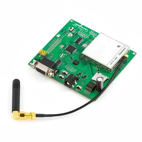
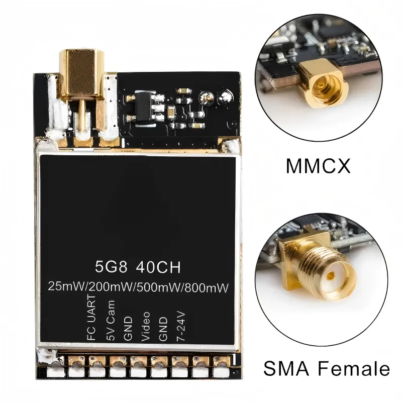
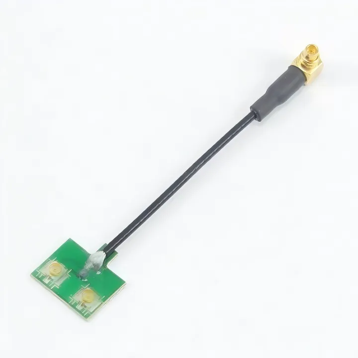
MMCX to SMA Connector Layout & Routing Guide

Most RF designs don’t fail in obvious ways.
They boot. They transmit. Sensitivity looks fine during bring-up. Nothing screams “problem.” The trouble usually starts later—after the enclosure is closed, after the antenna is mounted, or after someone touches the cable during testing. That’s often when the mmcx to sma connector quietly shows its influence.

Schematic of a compact RF module (e.g., GNSS, Cellular IoT) highlighting its onboard MMCX connector, contrasted with peripheral test equipment featuring SMA interfaces.

MMCX to SMA Adapter Choices for RF Modules

In compact RF hardware, connector decisions almost always arrive later than they should. By the time an engineer notices that a radio module exposes an MMCX connector, the antenna has already been selected, the enclosure outline is mostly fixed, and the test setup assumes an SMA interface by default.

A technical schematic showing how each connection interface—through patch panels, multiple BNC jumpers, and inline adapters—cumulatively introduces additional loss and reflection, impacting the total link budget.

75 Ohm BNC Cable Planning for HD Video Systems

Video systems rarely fail in obvious ways. A camera still powers on, a monitor still shows an image, and basic checks pass during installation. Yet weeks or months later, picture quality begins to drift. Edges soften, brief dropouts appear, or sync instability shows up only under motion or load. In many real-world installations, the root cause is not the camera, recorder, or display. It is the 75 ohm BNC cable quietly sitting between them, operating just outside its safe margin.

Illustration of MCX connector applications in compact RF modules (e.g., GPS, cellular modems).

MCX Connector Design Rules for RF Hardware

In compact RF hardware, connector decisions tend to arrive late. Antennas are debated. RFICs are simulated. Enclosures get revised again and again. The connector usually shows up after the system already “works,” quietly dropped into the schematic because the footprint fits.

Illustration of non-obvious signal path failure modes.

BNC Coaxial Cable Structure and Selection

Most signal paths don’t fail in obvious ways. They fade. A CCTV feed that once looked clean starts showing faint noise at night. A scope trace shifts slightly when someone reroutes a cable. A video link passes commissioning tests but becomes unstable after installation. In many cases, engineers first suspect the camera, the recorder, or the instrument itself, while the cable quietly escapes attention. That’s the hidden risk of treating a BNC coaxial cable as generic hardware instead of what it really is: a controlled part of the signal path.

Illustration of BNC-related products (e.g., connectors, cables, adapters) used in high-definition video systems.

BNC Video Cable Routing and Image Quality Control

In professional video systems, cables rarely get discussed during design reviews. Cameras, routers, codecs, and displays get the attention. The bnc video cable usually appears later—often selected from what’s already on the shelf. That sequencing is deceptive.When video issues show up in the field, they rarely look like clean failures. The image appears, but drops frames. A feed works at rehearsal, then glitches during the live show. Someone reseats a connector and the problem disappears—temporarily. In many of those cases, the root cause isn’t the camera or the switcher. It’s the cable in between.

Diagram distinguishing the terminology among BNC cable, BNC video cable, and BNC camera cable.

BNC Camera Cable CCTV Monitoring Selection and Cabling Guide

Why is the bnc camera cable the most overlooked part of a CCTV system?Most CCTV problems don’t fail loudly.The camera powers up. The DVR shows video. During installation, nobody complains. The system passes the “looks fine” test, which is often the only test it gets.Weeks later, the complaints start. Night footage looks rough. One channel has more noise than the others. Someone notices faint interference that wasn’t there before. At that point, attention usually goes to the camera, the DVR, or the power supply.

Illustration of the typical scenario where a 50-ohm BNC cable is often an afterthought in a test setup.

50 ohm BNC Cable Testing & Impedance Matching Guide

A 50 ohm BNC cable usually enters the setup after everything else already works.The instrument powers up.The DUT responds.Someone reaches for a cable because the connector happens to match.That timing is not accidental. It’s also where problems start.

Illustration of SMA connector application in scenarios where both space and frequency matter.

RF Connector Guide for Cables, Antennas and Test Systems

Preface Most RF systems don’t break in obvious ways. They don’t fail during bring-up. They don’t fail during basic testing. In many cases, they don’t even fail during early deployment. What happens instead is slower and harder to pin down: range shrinks, measurements drift, or a link that used to feel “solid” becomes sensitive to handling.

Diagram showing SMA connectors in different mechanical form factors: straight, right-angle, bulkhead, and panel-mount.

SMA Connector Selection for RF Cables and Antennas

Why does the SMA connector matter more than it looks? In most RF designs, the SMA connector is treated as solved hardware. It is familiar, inexpensive, and already sitting on the shelf. Engineers rarely debate it the way they debate antennas, RF chipsets, or matching networks. By the time an SMA interface shows up in the design, the radio already works and the enclosure shape is more or less fixed.

Diagram showing typical RF modules and use cases employing MMCX connectors.

MMCX Connector Guide for RF Modules & SMA Links

When does an MMCX connector become the right choice? In most RF projects, connector decisions arrive late. By the time an engineer starts debating whether to use an SMA, MMCX, or U.FL interface, the RF module is already selected, the enclosure outline is fixed, and the antenna strategy is mostly settled. At that point, the connector is no longer a blank-slate decision—it is a constraint-solving exercise.

Installation diagram of SMA jumpers inside a sealed enclosure.

SMA Male to Male Cable Jumpers Guide

Where does an sma male to male cable help? An sma male to sma male cable almost never shows up on a system diagram. It appears later—after the radio already works, after the enclosure looks “mostly done,” and after someone realizes two SMA female ports need to talk to each other right now.