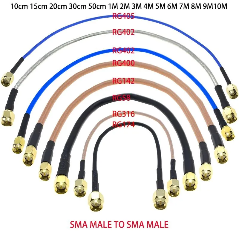
Logic Level Shifter Guide for I2C & MCU IO
A logic level shifter usually doesn’t look dangerous on a schematic. It’s small, cheap, and familiar. Many engineers add it late, once the MCU, sensors, and connectors are already locked in. Nothing about
We continuously share and publish original articles about electronic components and OEM/ODM/private label solutions. We hope these articles provide you with valuable insights to support your private label electronic components business.
If you don’t want to miss our article, please subscribe to our newsletter.
A logic level shifter usually doesn’t look dangerous on a schematic. It’s small, cheap, and familiar. Many engineers add it late, once the MCU, sensors, and connectors are already locked in. Nothing about
Most wireless projects do not fail because RF theory was misunderstood. They fail because a small assumption slipped through late in the build. A connector that looked right, a cable that threaded on smoothly, an extension added after the enclosure layout was already finalized—this is where RP-SMA vs SMA quietly causes trouble. On the surface, the two interfaces appear interchangeable. In practice, they are not. The difference rarely shows up as an obvious fault. Instead, it appears later, when 5 GHz throughput becomes inconsistent, when 6 GHz links lose margin first, or when field returns start coming back with the note “fits but doesn’t work.” This article focuses on practical identification and matching logic rather than formal definitions, with a simple goal: identify the port in seconds, match both ends once, and place orders without rework.
An SMA extension cable rarely gets much attention during early design. It’s passive. It’s inexpensive. And it’s often added late—after the enclosure, the antenna, and even the compliance plan are already “locked.”
A wifi antenna extension cable almost never looks like the source of a weak wireless link. It’s passive, inexpensive, and usually added late in a project—often after the enclosure, antenna choice, and even regulatory planning already feel “finished.” In real Wi-Fi systems, especially at 5 GHz and 6 GHz, that last-minute extension often decides whether a link feels stable or quietly fragile. Nothing fails outright. Instead, higher MCS rates drop first, roaming becomes inconsistent, and coverage shrinks just enough to frustrate users without pointing clearly to the cause.
An SMA connector almost never looks like the cause of a weak wireless link. It’s small, passive, inexpensive, and usually added late in the build. Yet in real Wi-Fi and IoT systems, many performance problems trace back to the connector layer—specifically, misidentifying SMA vs RP-SMA, choosing the wrong bulkhead thread length, or extending the antenna path without accounting for loss and reflections.
Wireless systems rarely fail because someone misunderstood RF theory. Much more often, they fail because a small assumption slipped through late in the build. A connector that looked right. A cable that threaded on smoothly. An extension added after the enclosure layout changed.
A sma antenna cable rarely looks like a design risk. It’s passive, inexpensive, and usually added late in a build—sometimes after the enclosure, the antenna, and even the compliance plan are already “done.” Yet in real Wi-Fi and IoT systems, especially at 5 GHz and 6 GHz, that short coax run often decides whether a device feels stable or annoyingly fragile.
Open almost any modern microcontroller datasheet and you’ll find a familiar reassurance: GPIO and ADC pins include internal ESD or clamp structures tied to the supply rails. On paper, that sounds like sufficient protection. In real hardware, it rarely is.
Most power or control boards don’t fail loudly. They age. A relay that used to release cleanly starts sticking. A MOSFET that passed every bench test begins to run warmer each month. An MCU pin degrades without ever seeing an obvious fault.
A wifi antenna cable rarely looks like a design risk. It’s passive, inexpensive, and usually added late in the build. Yet in Wi-Fi systems, especially at 5 GHz and 6 GHz, that short length of coax often decides whether a product feels solid or frustrating.
Routers and access points rarely fail because RF theory was misunderstood. Much more often, they fail because something small was assumed. A connector that looked right. An antenna that screwed on without resistance. A short extension added at the last minute because the enclosure layout changed.
A schottky diode usually doesn’t get much attention when a circuit is first sketched. It sits quietly near a connector, a regulator, or a signal pin, looking interchangeable with half a dozen other diodes in the parts drawer. Yet in finished hardware, these parts often end up deciding whether a product behaves politely—or spends its life flirting with edge cases.
I'll get back to you very soon.
