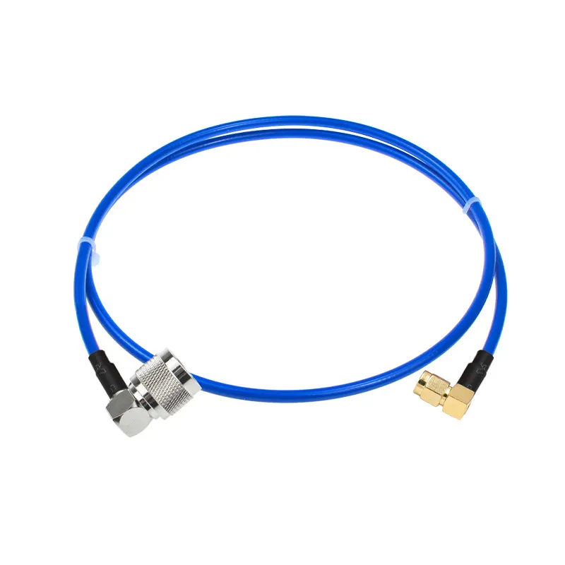
RF Coaxial Cable Selection & Application Guide
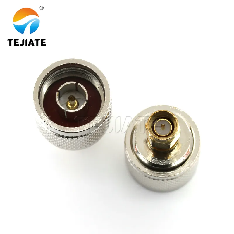
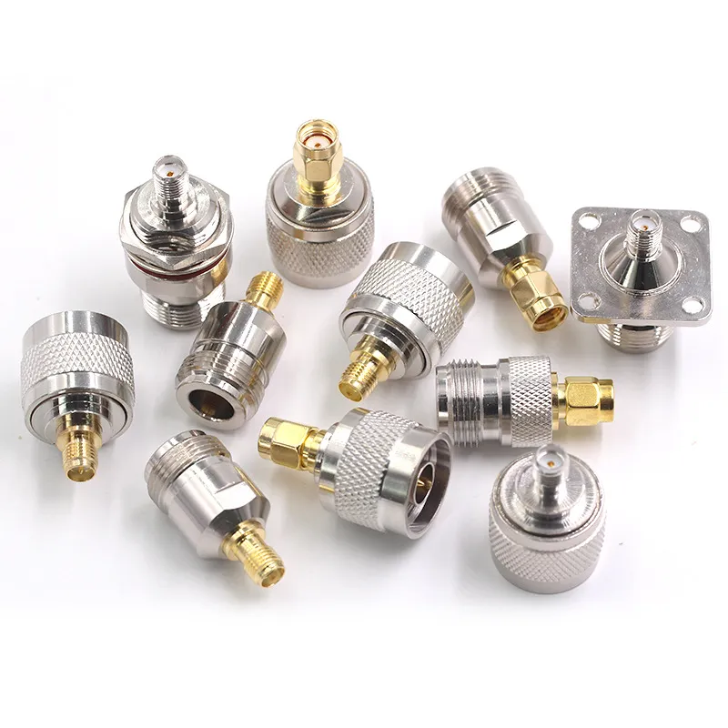
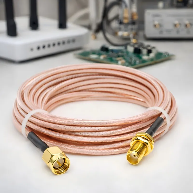
Most RF systems do not fail because of antennas. And surprisingly, they rarely fail because of radios either. More often, the quiet component between them becomes the problem. That component is the RF coaxial cable. At first glance, a coax cable seems simple. It connects two RF ports. If the connectors mate and the signal passes, everything appears fine. Engineers usually move on to more interesting parts of the system.