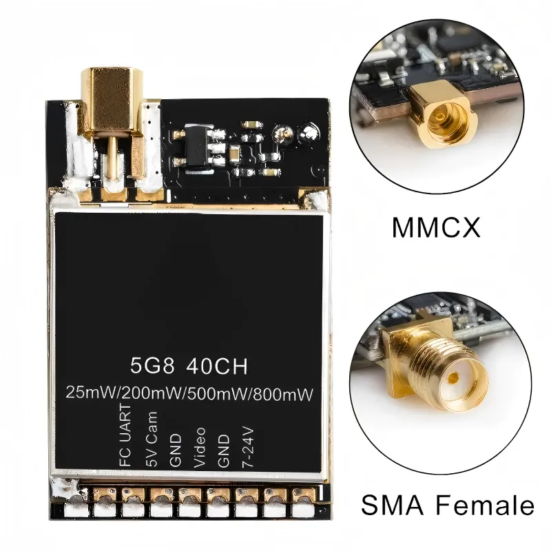
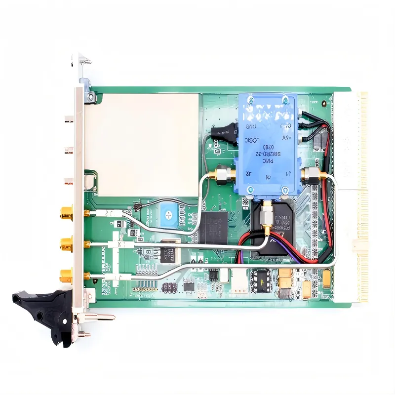
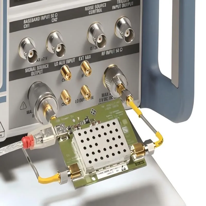
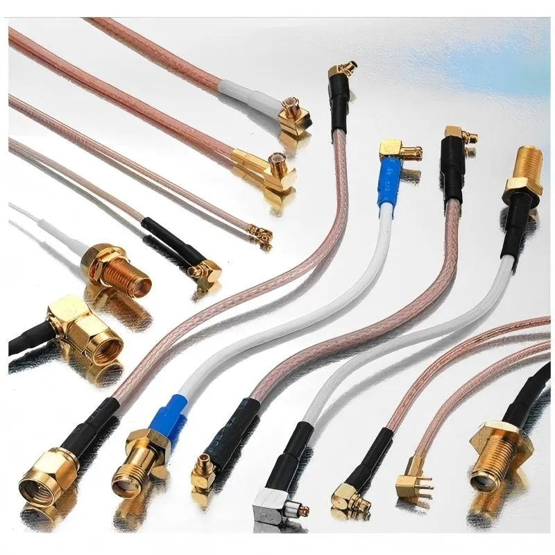
We share everything about Electronic Components OEM, ODM, or private label solutions...

We continuously share and publish original articles about electronic components and OEM/ODM/private label solutions. We hope these articles provide you with valuable insights to support your private label electronic components business.

If you don’t want to miss our article, please subscribe to our newsletter. 

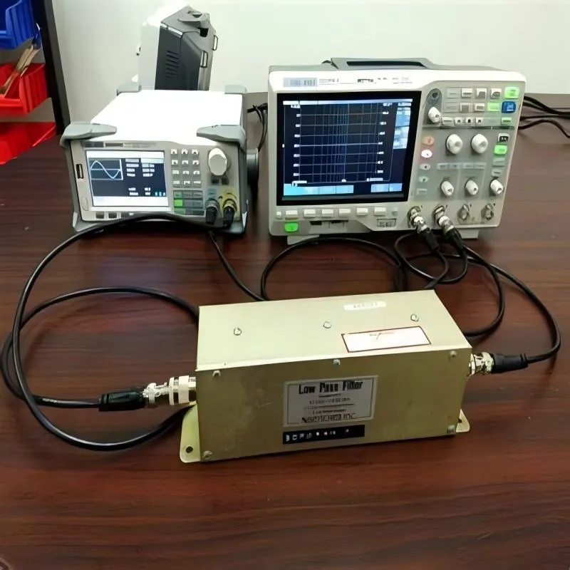
Illustration of the typical scenario where a 50-ohm BNC cable is often an afterthought in a test setup.

50 ohm BNC Cable Testing & Impedance Matching Guide

A 50 ohm BNC cable usually enters the setup after everything else already works.The instrument powers up.The DUT responds.Someone reaches for a cable because the connector happens to match.That timing is not accidental. It’s also where problems start.

Illustration of SMA connector application in scenarios where both space and frequency matter.

RF Connector Guide for Cables, Antennas and Test Systems

Preface Most RF systems don’t break in obvious ways. They don’t fail during bring-up. They don’t fail during basic testing. In many cases, they don’t even fail during early deployment. What happens instead is slower and harder to pin down: range shrinks, measurements drift, or a link that used to feel “solid” becomes sensitive to handling.

Diagram showing SMA connectors in different mechanical form factors: straight, right-angle, bulkhead, and panel-mount.

SMA Connector Selection for RF Cables and Antennas

Why does the SMA connector matter more than it looks? In most RF designs, the SMA connector is treated as solved hardware. It is familiar, inexpensive, and already sitting on the shelf. Engineers rarely debate it the way they debate antennas, RF chipsets, or matching networks. By the time an SMA interface shows up in the design, the radio already works and the enclosure shape is more or less fixed.

Diagram showing typical RF modules and use cases employing MMCX connectors.

MMCX Connector Guide for RF Modules & SMA Links

When does an MMCX connector become the right choice? In most RF projects, connector decisions arrive late. By the time an engineer starts debating whether to use an SMA, MMCX, or U.FL interface, the RF module is already selected, the enclosure outline is fixed, and the antenna strategy is mostly settled. At that point, the connector is no longer a blank-slate decision—it is a constraint-solving exercise.

Installation diagram of SMA jumpers inside a sealed enclosure.

SMA Male to Male Cable Jumpers Guide

Where does an sma male to male cable help? An sma male to sma male cable almost never shows up on a system diagram. It appears later—after the radio already works, after the enclosure looks “mostly done,” and after someone realizes two SMA female ports need to talk to each other right now.

A conceptual image depicting an RF project timeline where major components (radio, antenna, enclosure) are decided early, while the SMA coaxial cable is added later as an afterthought, with a question mark or subtle performance graph drift symbolizing resulting issues.

SMA Coaxial Cable Structure & Selection

In RF hardware, the sma coaxial cable almost never feels like a design driver. It shows up late, often after the radio already works, the antenna has been selected, and the enclosure layout feels “mostly done.” That timing is exactly why it causes problems. On paper, the cable looks passive. In practice, it sits at a mechanical and electrical boundary where small compromises quietly eat into margin. Engineers usually notice only when performance drifts, measurements become sensitive to touch, or a system that passed early validation starts behaving differently in the field. This guide focuses on how sma coaxial cable actually behaves inside real RF links, how to read its structure correctly from datasheets, and how to turn cable selection into a repeatable workflow instead of a last-minute fix.

A conceptual image contrasting the immediate, measurable RF performance (like a clean signal on a scope) with the slow, mechanical degradation of a connector (like a worn or loose SMA jack), highlighting the cable's role in preventing the latter.

SMA Male to Female Cable Extension Guide

Where does an sma male to sma female cable actually help in RF systems? If you look back at most RF projects that aged poorly, the failure usually wasn’t dramatic. The link still worked. The radio still powered up. But performance drifted. Connectors loosened. Touching the cable changed readings just enough to be annoying.

An image showing a modular RF front-end PCB with predefined connector locations, next to a small set of standardized SMA antenna cable SKUs with labeled length and type.

SMA Antenna Cable Length, Loss & Use Cases

In many RF products, the antenna gets most of the attention. Engineers debate gain, radiation pattern, polarization, and placement. The cable that connects that antenna to the radio, however, is often treated as an afterthought. That assumption usually holds—until it doesn’t. In Wi-Fi routers, IoT gateways, and FWA CPEs, the sma antenna cable often becomes the quiet bottleneck in the RF link. It introduces loss, it sees mechanical stress, and it lives closer to the outside world than almost any other RF component. Understanding where this cable sits in the system, how long it can realistically be, and how to match it with the right coax family makes the difference between a link that barely passes and one that works reliably for years.

An annotated diagram or photo of a typical embedded product (e.g., IoT gateway, industrial controller) highlighting touchable ESD entry points: USB/ Ethernet/ RF connectors, buttons, metal housing, exposed screws, and debug headers.

ESD Protection Devices for Embedded Systems

Electrostatic discharge rarely shows up as a clean, dramatic failure. No smoke. No obvious damage. The board powers up, firmware runs, and early validation looks fine. That’s exactly why ESD problems in embedded systems tend to linger longer than they should. Most teams encounter ESD indirectly. A controller resets once every few days. A sensor output jumps under dry conditions. A USB port disconnects only when someone touches the cable shell. Engineers chase firmware timing, buffer overruns, or power sequencing issues—often for weeks—before realizing the root cause was electrical stress, not software logic.

Side-by-side comparison of ESD protection circuits for a low-speed interface (like I2C with simple diode) and a high-speed interface (like USB with a low-capacitance array or specialized protector).

ESD Protection Circuit Design for Mixed PCBs

Electrostatic discharge almost never shows up as a clean, dramatic failure on a mixed-signal PCB. There is usually no burnt component, no obvious short, no instant death. The board powers on. Firmware runs. Interfaces appear functional. That is precisely what makes ESD so dangerous in real products. The damage is often cumulative and indirect. A unit works on the bench, passes production test, and even survives early validation. Weeks later, after installation, handling, or repeated cable insertion, odd behavior begins to surface. A controller resets under seemingly random conditions. A communication link drops once a day. An analog reading spikes for no clear reason. In many mixed-signal designs, these are the first signs that the ESD protection circuit strategy was either incomplete or ineffective.

Photo of an automotive ECU undergoing ESD testing in a lab, showing an ESD gun being applied to a connector while communication is monitored.

ESD Diode Guide for Automotive CAN & LIN

In automotive electronics, the ESD diode is rarely a headline component. It doesn’t define performance, it doesn’t move BOM cost in a visible way, and it usually appears late—often after the CAN or LIN interface already works on the bench. That timing is exactly why ESD problems tend to surface late as well.

Micrograph or illustration showing physical ESD damage on a PCB or semiconductor die, such as melted traces or gate oxide punctures.

ESD Protection for Microcontroller I/O

Electrostatic discharge rarely announces itself with a dramatic failure. Most of the time, it arrives quietly. A prototype boots normally on the bench, firmware runs without complaint, and basic tests pass. Then the board is installed in an enclosure, a cable gets longer, or someone plugs a connector during a dry winter morning. Suddenly, there is a reset. Or a communication error that disappears after a power cycle. That delayed, inconsistent behavior is where ESD protection around microcontroller I/O pins becomes relevant—and where it is most often underestimated.