We share everything about Electronic Components OEM, ODM, or private label solutions...

We continuously share and publish original articles about electronic components and OEM/ODM/private label solutions. We hope these articles provide you with valuable insights to support your private label electronic components business.

If you don’t want to miss our article, please subscribe to our newsletter. 

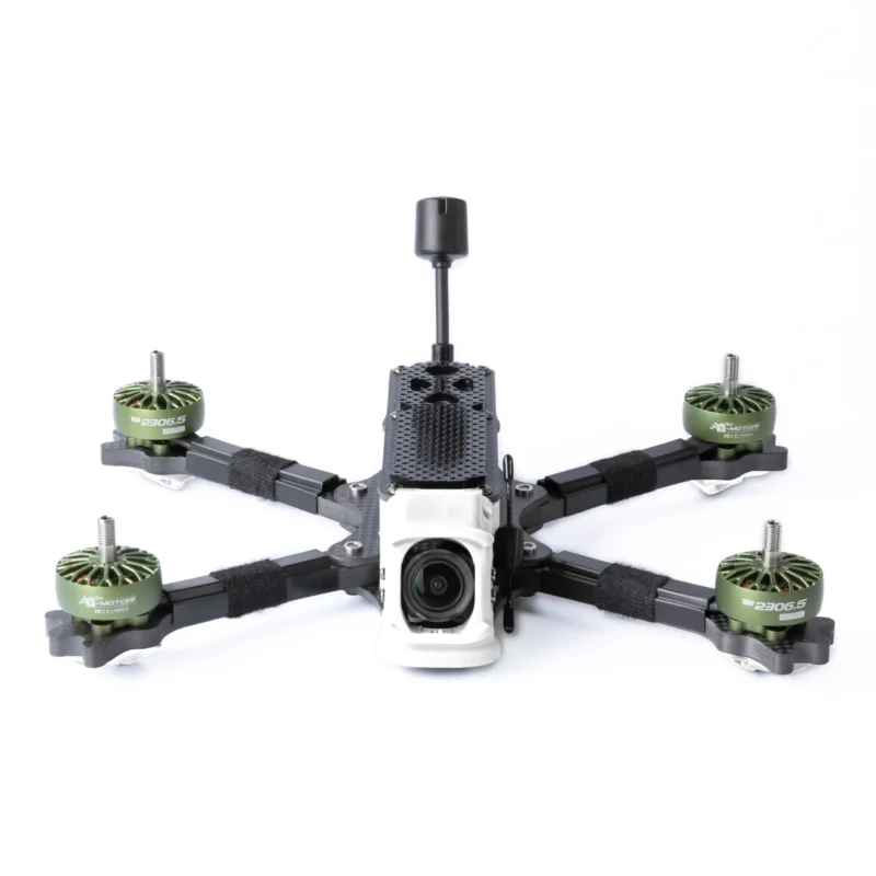
Side view of a drone showing antenna protruding at an angle, with potential interference from frame and props

FPV Antenna Guide for 5.8GHz Drone Setup

A small FPV build lands on the bench. Everything else looks right. VTX is powered. Camera feed is clean. Channels are set correctly. Then the pilot walks ten meters away. The image starts breaking up. Not gone—just unstable. Flicker. Noise. Occasional blackouts. At this point, most people don’t suspect the antenna. They look at power output, firmware, even interference. But in many setups, the weakest link is sitting right on top of the drone—small, overlooked, and chosen last.
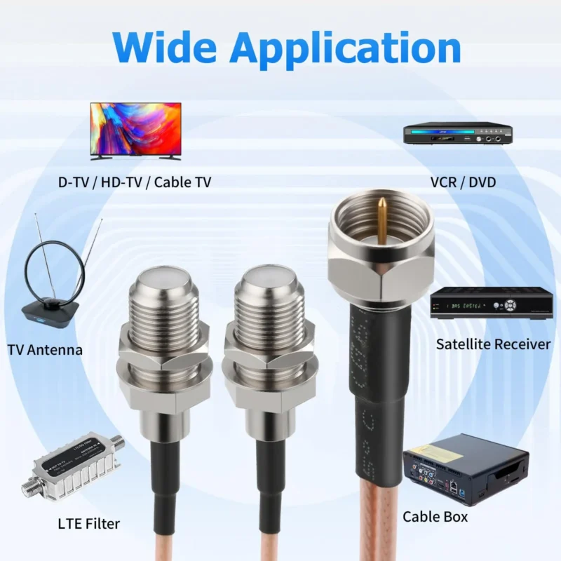
Diagram comparing different coax port types: wall plate (signal entry), TV (endpoint), and antenna (signal source)

Coax Splitter Guide for TV Systems

A wall-mounted TV goes up cleanly. Cable hidden. Plate aligned. Nothing visible. Then a second room gets connected—and the signal starts breaking. The splitter gets blamed first. It usually isn’t the real problem. What changed is not the device. It’s the signal path.

Close-up product photo of TV coax connector parts including F-type male and female fittings, coupler, splitter, and right-angle coax adapter on a neutral surface

Coax Cable Connector Guide for TV Systems

A TV goes on the wall, the bracket sits close to the plaster, and suddenly the coax line that worked fine in open air no longer fits cleanly. The cable sticks out too far. The connector presses against the wall. Someone grabs the first small metal part they can find online — coupler, splitter, adapter, it all looks similar enough in the listing photo — and the install turns messy fast.

Diagram showing SMA connectors on compact radios and BNC connectors on test instruments, with an adapter bridging them

SMA to BNC Adapter for RF Work

Place SMA to BNC adapter inside a real RF workflow A typical lab setup rarely fails because of a missing component. The radio module is already powered. The antenna has been selected. A short piece of coax sits on the bench ready to connect everything.The instrument on the bench — maybe a spectrum analyzer from ten years ago — still uses BNC. At that moment, the quickest fix is usually a sma to bnc adapter pulled from a drawer full of connectors. Tighten it onto the SMA port, snap the BNC cable onto the other side, and the measurement appears on screen.

Photograph of a rigid BNC to SMA adapter, a short metal body with BNC on one end and SMA on the other

BNC to SMA Cable for RF Systems

A spectrum analyzer is already on the bench. The device under test is powered up. Someone reaches for the RF cable. Then the mismatch shows up. The instrument exposes a BNC port. The module on the bench has SMA. At first the fix looks trivial. Grab an adapter, tighten it, move on. In many labs that is exactly what happens. But the moment that connection becomes part of the signal path—especially above a few hundred MHz—the difference between a rigid adapter and a short BNC to SMA cable starts to matter more than expected.

Table or diagram showing common applications of SMA adapter cables: module to panel, radio to analyzer, internal jumper, and DUT to equipment

SMA Adapter Cable for RF Systems

Introduction A small RF board lands on the bench. The module exposes an SMA connector. The spectrum analyzer sitting beside it still uses BNC. Someone reaches for the adapter drawer. A rigid SMA-to-BNC adapter would technically solve the mismatch. The threads mate, the signal passes, and the measurement shows up on the screen.

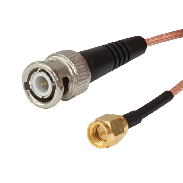
Photograph of a finished SMA to BNC cable assembly, with SMA connector on one end and BNC connector on the other

SMA to BNC Cable for RF Systems

Connect SMA radios to BNC instruments, legacy gear, and bench fixtures The connector mismatch usually appears late. A small RF module is already powered on. Someone routes the antenna cable through the enclosure wall. The test setup is ready—spectrum analyzer on the bench, coax already lying across the table. Then the mismatch shows up.

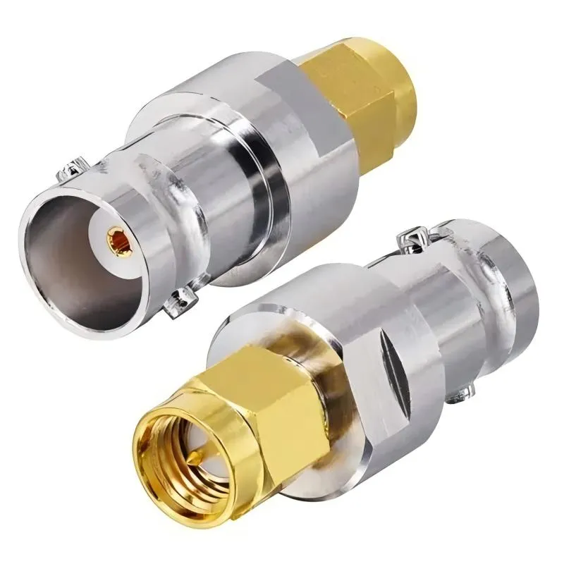
Photograph of a rigid BNC to SMA adapter, with BNC connector on one end and SMA on the other

BNC to SMA Adapter for RF Systems

Place BNC to SMA adapter inside a real RF workflow Connector mismatches rarely appear in schematics. They appear on the bench. A radio module arrives with a small SMA port. The measurement gear next to it—often older lab equipment—still exposes BNC connectors. The test setup already includes cables, attenuators, and an antenna path. Someone reaches for a quick mechanical bridge.

Diagram showing a connector mismatch on a workbench between an SMA device and a BNC instrument

SMA to BNC Adapter for RF Work

Introduction A connector mismatch rarely shows up in the design review slides. It shows up on the workbench. A small RF module arrives with an SMA port. The lab instrument beside it—often an older spectrum analyzer or signal generator—still exposes BNC. Everything else in the setup is ready: firmware loaded, antenna selected, cable already on the bench. Then someone notices the ports don’t match.

Diagram showing an SMA adapter cable as a flexible transition between a module and a panel connector

SMA Adapter Cable for RF Systems

A small connector mismatch usually shows up late. The radio module is already selected. The enclosure drawing is almost finished. Someone on the bench connects the RF output to a test instrument and notices the ports don’t match. SMA on the device. BNC on the instrument. Or sometimes the port sits recessed behind a panel wall and the rigid adapter that “should work” simply doesn’t reach.

Conceptual diagram showing a 50-ohm coaxial cable connecting a radio module to an antenna in an RF system

50 Ohm Coaxial Cable for RF Systems

Map 50 ohm coaxial cable to real RF links A system comes back from field testing with a strange complaint: the link budget looked fine in the lab, but once the unit was mounted on a vehicle, signal stability dropped. The radio module checks out. The antenna gain matches the spec sheet. Firmware hasn’t changed. The quiet piece between them turns out to be the difference.

Close-up of RG316 coaxial cable, showing its small diameter, PTFE dielectric, and braided shield

50 Ohm Coaxial Cable Selection Guide

The problem usually doesn’t appear during the first test. A radio module sits on the bench. Someone connects it to an antenna through a short coax jumper. The signal shows up on the analyzer and the system seems healthy. Nothing looks suspicious. Later, the same setup moves inside a product enclosure. The antenna is mounted on the panel. The cable path becomes longer, the routing tighter, and the RF path now includes connectors, bulkheads, and sometimes adapters.