
A cable can be mechanically connected and still be the wrong RF connection.
This happens frequently when an N Type antenna interface needs to connect with a compact SMA port on an RF module, test fixture, or wireless device. The threads match, the adapter can be tightened, and the system may even pass a basic continuity check. The problem appears later: unexpected VSWR, unstable measurements, or performance loss near the upper operating frequency.
An n type to sma adapter is often treated as a simple mechanical converter, but RF engineers usually need to consider more than the connector shape. The adapter must match the interface direction, impedance, frequency range, cable system, and measurement requirements.
A typical RF path may include an outdoor antenna using an N Type connector, an SMA-equipped radio module, and a coaxial cable assembly between them. Without the correct conversion interface, the entire signal path can become difficult to validate.
How Does an N Type to SMA Adapter Connect Different RF Systems?
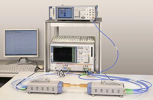
This image shows a professional RF test setup using coaxial connections and measurement equipment. N Type to SMA adapters help engineers connect different RF interfaces during antenna testing, microwave measurements, and signal analysis while maintaining reliable signal transmission.
N Type and SMA connectors were developed for different application environments. N Type connectors are commonly found in antenna systems, outdoor communication equipment, and larger RF assemblies where mechanical strength and environmental durability are important. SMA connectors are widely used on compact RF modules, microwave components, development equipment, and laboratory test systems where smaller size is valuable.
An n type to smaadapter provides the interface transition between these two connector families without requiring a complete cable replacement.
The practical value is not only the physical conversion. A correctly selected adapter allows engineers to integrate different RF components while keeping the original equipment configuration.
| Interface | Common Application | Typical Design Consideration |
| N Type | Antennas, base stations, outdoor RF equipment | Mechanical strength, cable routing, environmental exposure |
| SMA | RF modules, PCB assemblies, test equipment | Compact size, precision connection, high-frequency testing |
| N to SMA Adapter | Interface conversion between systems | Gender, impedance, frequency compatibility |
For example, an antenna installation may already use an N Type coaxial cable because the cable route is outdoors. The connected communication module may only provide an SMA port due to PCB space limitations. In this situation, replacing the entire cable assembly may increase cost and introduce unnecessary installation changes. An adapter provides a simpler transition point.
However, the adapter should not be selected only by looking at connector names. “N to SMA” describes an interface family, but the actual product specification depends on the two sides of the adapter.
Before ordering, engineers normally need to confirm:
- N Type side gender
- SMA side gender
- 50Ω or 75Ω system requirement
- operating frequency
- installation environment
- required RF performance
A common sourcing mistake is selecting an adapter based on a product image. Two adapters may look almost identical but have opposite gender combinations or different internal structures.
Why Does Electrical Compatibility Matter Beyond Mechanical Connection?
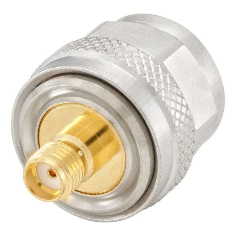
An RF adapter is part of the transmission path. Every additional interface introduces another point where impedance discontinuity, insertion loss, or mechanical tolerance can affect the signal. Connector alignment, dielectric structure, center contact positioning, and machining accuracy all influence RF behavior.
This is why a part that works well in a basic wireless application may not be suitable for precision microwave measurement.
For RF test engineers, the adapter itself becomes part of the measurement chain. A poor-quality or incorrectly specified adapter can affect calibration results and create confusion when troubleshooting a system.
Where Are N Type to SMA Adapters Commonly Used?
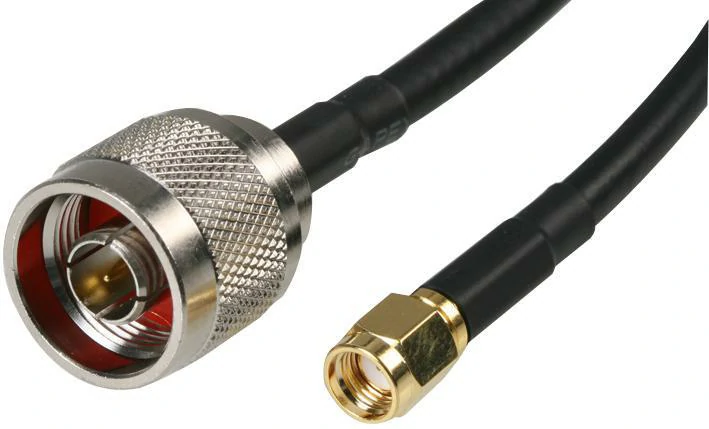
This image shows an N Type to SMA coaxial cable assembly used for RF signal transmission between different connector interfaces. Compared with separate adapters, cable assemblies reduce additional connection points and are commonly used in permanent RF installations.
However, adapter usage should also be controlled. Excessive adapter stacking increases the number of RF interfaces in the signal path. Each connection adds potential insertion loss and reflection points. For permanent installations, a correctly specified cable assembly may provide better repeatability.
How Do You Choose Between N Male to SMA Female and SMA Male to N Female?
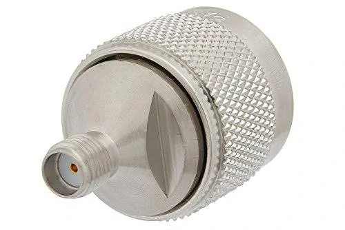
This image shows an N male to SMA female adapter designed for 50Ω RF systems. It is commonly used for connecting antenna cables, communication equipment, RF modules, and test instruments that use different coaxial connector interfaces.
Choosing the wrong direction is one of the most common purchasing errors.
Typical combinations include:
| Adapter Type | Connection Example | Common Use |
| N Male to SMA Female | N cable/equipment → SMA device | Connecting N Type cable to SMA module |
| SMA Male to N Female | SMA equipment → N cable/system | Connecting SMA cable to N Type interface |
A buyer should check the actual mating ports rather than relying on the application description.
For example:
- “N antenna to SMA module” does not define the adapter completely.
- The antenna connector may be N Female or N Male.
- The module connector may be SMA Female or SMA Male.
The correct specification should describe both sides clearly:
N Male to SMA Female Adapter, 50Ω, operating frequency range required for the RF system
This type of description gives suppliers enough information to confirm the correct structure.
A useful rule during procurement is to identify the fixed equipment ports first, then select the adapter gender. Do not start from the adapter name alone.
The connector may physically fit but still prevent proper mating if the center contact, socket, or thread configuration does not match.
N Type to SMAAdapter Direction Selection Table
| System Requirement | Recommended Adapter Direction | Check Before Ordering |
| N Type cable connects to SMA device | N Male to SMA Female | Confirm SMA equipment port |
| SMA cable connects to N equipment | SMA Male to N Female | Confirm N equipment interface |
| Antenna installation | Check N side first | Verify antenna connector gender |
| RF module connection | Check SMA side first | Confirm module connector type |
| Test equipment setup | Confirm instrument port | Match calibration configuration |
Selecting the adapter direction correctly prevents one of the simplest but most expensive RF sourcing mistakes: receiving a connector that fits the description but cannot connect to the actual system.
How Does 50 Ohm Matching Affect N Type to SMA Adapter Selection?
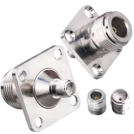
This image shows bulkhead-style N Type to SMA adapters with flange mounting structures. These adapters are designed for fixed installation in RF equipment panels, test fixtures, communication systems, and microwave devices requiring stable mechanical support.
A connector can be the correct size, have the correct thread, and still create an RF problem.
This is usually caused by ignoring impedance.
In an RF system, the adapter is not an isolated mechanical part. It sits between the cable, antenna, and equipment port. If one part of the signal path does not follow the same impedance standard, the reflected signal can increase and the measurement result may change.
Most N Type to SMA adapters used for wireless communication, antenna systems, and RF testing are based on a 50Ω system. This matches the majority of RF cables, SMA interfaces, and N Type components used in these applications.
Before selecting an adapter, engineers normally confirm the complete connection:
- Antenna impedance
- Cable impedance
- Adapter impedance
- Equipment port impedance
A common purchasing mistake is checking only the connector family. The description “N to SMA adapter” confirms the interface conversion, but it does not confirm whether the part belongs to the correct RF system.
For example, N Type connectors can appear in both 50Ω and 75Ω applications. The external appearance may be similar, but the internal dimensions are different. Using the wrong version in a 50Ω RF path can affect VSWR and return loss.
| Parameter | Why Engineers Check It |
| Impedance | Confirms the adapter matches the RF system |
| VSWR | Shows signal reflection caused by discontinuity |
| Return Loss | Indicates reflected RF energy |
| Insertion Loss | Shows signal loss through the adapter |
In a simple antenna connection, a small amount of mismatch may not immediately cause a visible problem. In a test environment, the same mismatch can appear as unstable measurements or inconsistent calibration results.
This is why RF engineers usually evaluate the adapter together with the complete signal chain instead of treating it as a simple connector accessory.
How Should You Match N Type to SMA Adapters With Coaxial Cables?
The adapter choice is closely related to the cable behind the connector.
An N Type interface is often used with larger coaxial cables because the connector structure provides good mechanical support. SMA is frequently selected for smaller RF modules where installation space is limited.
The adapter creates the transition between these two environments, but the cable remains a major factor.
When selecting an n coax adapter or n coaxial adapter, check:
- Cable diameter
- Cable construction
- Operating frequency
- Installation space
- Bend requirement
- Termination method
A connector designed for RG58 or RG142 cable should not automatically be substituted with a connector designed for RG316. Even if the front SMA or N interface is identical, the rear cable attachment area may be completely different.
This is a common issue during procurement. The buyer confirms the front interface but forgets that the connector body must match the cable.
A complete RF requirement should normally include:
| Specification Item | Example Requirement |
| Interface A | N Male |
| Interface B | SMA Female |
| Cable Type | RG316 / RG142 / LMR series |
| Impedance | 50Ω |
| Frequency | DC–6 GHz / DC–18 GHz |
| Assembly Length | Required cable length |
| Application | Antenna, test, module connection |
For prototype testing, an adapter may be the fastest way to connect existing hardware. Engineers can change modules, antennas, or instruments without rebuilding the complete cable.
For production equipment, the situation is different.
A permanent RF installation usually benefits from reducing unnecessary connection points. Every additional interface adds another mechanical joint. In high-frequency systems, repeated assembly, vibration, and handling can also influence long-term consistency.
Should You Use an Adapter or a Complete N Type to SMA Cable Assembly?
Both options solve different connection problems.
An adapter is mainly used when flexibility matters.
Typical situations:
- Production equipment
- Fixed antenna installation
- Repeated manufacturing
- Systems requiring controlled routing
| Connection Method | Suitable Situation | Engineering Consideration |
| Separate N Type to SMA Adapter | Flexible setup changes | More connection points |
| N to SMA Cable Assembly | Fixed system connection | Need correct cable selection |
| Adapter plus Extension Cable | Prototype or temporary setup | Verify added loss |
A frequent misunderstanding is assuming an adapter is always the better solution because it is easier to install.
For a quick laboratory connection, that is often true.
For a production cable harness, fewer interfaces usually make inspection and assembly control easier.
The decision depends on whether the system needs flexibility or repeatability.
How Does Frequency Range Affect N Type to SMA Adapter Selection?
The connector name alone does not determine whether an adapter is suitable for a certain frequency.
A standard N Type to SMA adapter may work well at several GHz, but the same adapter may not be appropriate for a microwave measurement system operating near the upper limit.
Before ordering, check:
- Maximum operating frequency
- VSWR specification
- Insertion loss
- Application environment
For example, an adapter used between an antenna and wireless module may have different requirements from one used with a vector network analyzer.
At higher frequencies, mechanical details become more sensitive.
The following factors can influence RF behavior:
- Center contact alignment
- Contact machining accuracy
- Dielectric material
- Connector interface condition
A small dimensional difference that has little effect at lower frequencies can become visible when the wavelength becomes shorter.
This is why precision microwave adapters usually require tighter manufacturing control and more detailed inspection.
How Much Frequency Margin Should You Keep When Selecting an Adapter?
Selecting an adapter exactly at the operating frequency leaves little room for system variation.
A practical way to evaluate the choice is:
Frequency Margin Ratio = Adapter Rated Frequency ÷ Maximum Operating Frequency
Example:
A system operates at 6 GHz.
| Adapter Rating | Margin Ratio | Evaluation |
| 6 GHz | 1.0× | Limited margin |
| 12 GHz | 2.0× | More suitable |
| 18 GHz | 3.0× | Better for sensitive testing |
The higher rating does not automatically mean lower insertion loss in every application. Cable type, connector design, and assembly quality still affect the final result.
The purpose of frequency margin is to avoid selecting a component that operates too close to its limit.
How Can RF Engineers Verify an N Type to SMA Adapter Before Installation?
A new adapter should be checked before being installed into a valuable RF system.
The first step is mechanical inspection:
- Thread condition
- Connector face cleanliness
- Center contact position
- Plating condition
- Physical damage
A continuity test can confirm the electrical path exists, but it cannot confirm RF behavior.When a system shows abnormal VSWR or unstable measurements, engineers can quickly determine whether the adapter, cable, or connected equipment should be investigated first.
How Do You Compare N Type to SMA Adapters With Other RF Conversion Options?
An RF system rarely keeps the same connector standard from beginning to end.
A typical project may start with an antenna using an N Type interface, connect through a coaxial cable, enter a compact RF module through SMA, and later connect to test equipment with another interface. During development and maintenance, engineers often need to convert between connector families without redesigning the whole RF path.
This is where RF adapters become practical.
However, the wrong conversion can create unnecessary problems. A connector may physically mate, but the application requirement may still be wrong.
Before comparing different adapter combinations, engineers usually look at three questions:
- Where is the signal coming from?
- Where does the signal need to go?
- What operating conditions must the connection handle?
An n type to smaadapter is commonly selected when a stronger outdoor RF interface needs to connect with a compact internal RF port.
For other situations, different conversions may be more suitable.
When Is N Type to SMA a Better Choice Than Other RF Adapters?
The difference between connector families is not only the outer shape.
Each connector type has developed around certain application environments.
| Connector Combination | Typical System Position | Common Reason for Selection |
| N Type to SMA | Antenna side to RF module side | Connect larger coax systems with compact RF devices |
| SMA to BNC | Test equipment connection | Quick connection between different instruments |
| N Type to BNC | Communication and measurement systems | Connect existing N cables with BNC equipment |
| N Type to TNC | Mobile and communication systems | Threaded connection with different equipment requirements |
For example, an antenna installation may already have an N Type cable routed through an enclosure. Replacing the cable because the internal module uses SMA may increase assembly time and require mechanical changes.
In this case, an N Type to SMA adapter may be the simpler solution.
On the other hand, if the equipment is a laboratory instrument with a BNC port, converting N Type to SMA first and then SMA to BNC creates an unnecessary connection chain.
More adapters do not always mean more flexibility.
How Do SMA to BNC and N Type to SMA Adapters Differ in RF Applications?
BNC is often selected where fast connection and frequent equipment changes are more important.
A technician working with test equipment may connect and disconnect BNC interfaces many times during daily measurements. An RF module designer may prefer SMA because the smaller threaded interface fits better into compact hardware.
The choice depends on the equipment environment.
A simple comparison:
| Item | SMA | BNC |
| Connection Method | Threaded | Bayonet locking |
| Typical Usage | RF modules, microwave parts, test fixtures | Instruments, monitoring equipment |
| Mechanical Style | More secure after tightening | Faster connection/disconnection |
| Common Adapter Need | Module interface conversion | Laboratory equipment compatibility |
When selecting between an N Type to SMA adapter and another conversion option, the final equipment port should decide the direction.
A supplier receiving only “need SMA adapter” cannot know whether the customer needs:
- SMA male to N female
- SMA female to N male
- SMA to BNC
- SMA cable assembly
The connector name alone is not enough for RF sourcing.
How Can Engineers Avoid Wrong Adapter Selection During Procurement?
Many adapter problems are not caused by manufacturing defects. They start earlier, during the specification stage.
A purchase request such as:
“Need N to SMA converter”
leaves several unanswered questions.
For a correct quotation, the supplier normally needs:
- N Type gender
- SMA gender
- Impedance
- Frequency range
- Mounting style
- Application
- Quantity
A better specification would look like:
N male to SMA female adapter, 50Ω, DC–6 GHz, used for antenna cable to RF module connection.
This information immediately reduces misunderstanding.
For production orders, additional details may be required.
| Specification | Example |
| Interface Side A | N Male |
| Interface Side B | SMA Female |
| Impedance | 50Ω |
| Frequency Requirement | DC–6 GHz |
| Mounting | Cable mount |
| Application | Wireless communication |
| Inspection | VSWR check if required |
This is especially important for OEM projects.
A prototype engineer may accept a general adapter for testing. A production engineer needs repeatable specifications because hundreds or thousands of assemblies may use the same component.
What Installation Details Affect N Type to SMA Adapter Reliability?
The adapter itself is only one part of the connection.
Mechanical installation can influence long-term use.
Several practical issues should be checked:
Connector tightening
Over-tightening may damage threads or deform mating surfaces.
Under-tightening may create unstable contact.
Cable stress
A heavy coaxial cable connected directly to a small SMA interface can create mechanical pressure on the connector.
The cable should be supported when necessary.
Environmental conditions
Outdoor applications may require attention to:
- Moisture protection
- Sealing structure
- Temperature variation
- Vibration
A standard laboratory adapter may not be suitable for an outdoor antenna installation.
Why Do RF Engineers Still Use N Type to SMA Adapters in New Designs?
A designer may test:
- Different antennas
- Different RF modules
- Different cable lengths
- Different measurement setups
Replacing every cable assembly during each design change is inefficient.
An adapter provides flexibility during this stage.
The decision depends on:
- Production quantity
- Installation space
- RF requirement
- Maintenance method
- Cost target
There is no universal answer.
A small adapter used in the correct location can simplify a system. The same adapter used without considering frequency, impedance, or mechanical stress can create problems.
FAQ
Can an N Type antenna connect directly to an SMA connector?
No. The two connectors use different mechanical interfaces. An N Type to SMA adapter or an N to SMA cable assembly is required.
Are all N Type to SMA adapters 50Ω?
Most RF versions are designed for 50Ω systems, but the specification should be confirmed before installation, especially when connecting with antennas or test equipment.
Can an adapter affect VSWR measurement?
Yes. The adapter becomes part of the RF path.
Is a cable assembly better than an adapter?
It depends on the application. Cable assemblies are often preferred for fixed production systems.
How should an N Type to SMA adapter be tested?
Mechanical inspection can check connector condition.
