
An RF port can mate correctly and still be wrong for the equipment.
This happens more often than it should. A purchasing drawing calls for an N type female connector, the sample screws onto the customer’s N male cable, continuity passes, and the front panel looks fine. Later, the mechanical team finds that the coupling nut cannot be turned comfortably. Or the internal cable pulls sideways on the receptacle. In another case, the connector body is mounted to a painted enclosure and the expected chassis bond is no longer present.
None of these problems comes from the basic N interface itself. They come from treating the female connector as an isolated component instead of part of the equipment architecture.
For a fixed RF port, the real definition includes the front interface, mounting structure, rear connection, grounding path, service access, cable loading, and RF acceptance criteria. If one of those items is still unclear, the connector selection is not finished.
What Role Does the N Female Port Play in the Equipment Architecture?
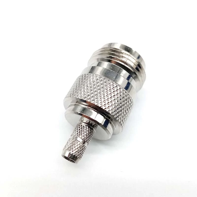
N type female coaxial connector with cable termination structure, suitable for RF equipment, antenna systems, test setups, and internal coaxial connections.
Before selecting a flange, jam nut, PCB pin, or rear cable connection, decide what the port is expected to do in the finished equipment.
That sounds obvious, but “N female” often appears in a BOM long before the mechanical boundary has been defined.
Define Whether the Port Is User-Facing or Internal
A female N interface can serve several different jobs:
- external antenna connection
- RF equipment input or output
- laboratory or production test port
- enclosure feedthrough
- internal RF transition between assemblies
The front interface may look nearly identical in each case, while the mechanical requirements are very different.
An external antenna port, for example, may be repeatedly connected to a relatively heavy feeder cable. The connector has to tolerate mating torque, cable weight, bending load, and service handling.
An internal transition usually sees much less user interaction. In that application, compact installation and clean routing may matter more than field accessibility.
A test fixture adds another constraint: repeated mating. The connector may be mechanically accessible and electrically correct, but frequent connection cycles can make replaceability more important than it would be on a sealed production enclosure.
That is why the equipment role should be defined before the connector body style.
Identify the Replaceable and Non-Replaceable Parts
A useful way to define the system is to separate the fixed equipment structure from the field-replaceable connection.
The chassis-mounted receptacle is usually part of the equipment BOM. The external N male cable may be installed or replaced by the user. The internal coaxial transition may only be accessible during assembly or repair.
These boundaries matter during sourcing.
If the external cable is expected to be replaced in the field, the fixed female port should absorb normal mating forces without transferring them into a small PCB connector or unsupported RF module.
A mechanically weak architecture can work perfectly on an open bench. Problems appear after installation, when a thick coaxial cable is routed downward, bent near the enclosure, or repeatedly disconnected during service.
The connector is therefore part of a load path, not just an RF path.
Set the Service Boundary Before Choosing the Connector Body
Imagine two products using the same front-side N female interface.
Product A has a short internal coax cable between the panel connector and RF module.
Product B uses a direct PCB-mounted N receptacle.
Electrically, both may satisfy the same nominal interface requirement. Mechanically, they behave differently.
The flexible coax in Product A can absorb panel tolerance, assembly movement, and some servicing stress. Product B can be more compact, but the PCB launch and mechanical support must be engineered so that mating forces do not damage the board or alter the RF transition.
This is one reason a product description such as “N female, 50 ohm” is not enough for production purchasing.
The broader N Type Connector Guide can be used for general interface selection. For a fixed equipment port, the next step is defining exactly how that interface becomes part of the enclosure.
How Do You Separate a Receptacle, Feedthrough, and Cable-End Female?
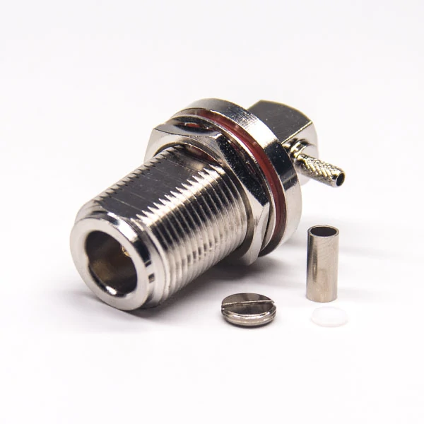
N type female panel mount connector designed for fixed RF equipment ports, featuring a threaded bulkhead body, mounting nut, sealing structure, and rear coaxial connection.
The word “female” only tells you part of the interface.
It does not tell you how the connector mounts, what happens behind the panel, how the shield is terminated, or whether the part is intended to carry a cable.
That distinction becomes critical when drawings, supplier descriptions, and purchasing language use “N female connector” as if every female version were interchangeable.
Identify a Fixed Receptacle by Its Rear-Side Architecture
A fixed N female receptacle may use several rear structures:
- solder cup
- PCB pin
- internal coaxial tail
- adapter or feedthrough interface
The correct option depends on the equipment design.
A solder-cup version may suit a short manually assembled internal connection. A PCB version requires a controlled RF launch and adequate mechanical support. A coax-tail design gives more routing freedom between the chassis and module.
The front-side mating interface alone cannot tell you which one belongs in the assembly.
Distinguish an Inline Female Adapter From a Chassis Port
A female-to-female adapter mainly solves an interface-conversion or extension problem.
A chassis receptacle has more jobs.
It may need to provide:
- mechanical mounting
- a controlled load path
- chassis bonding
- environmental sealing
- rear-side RF connection
- service access
An inline adapter can sometimes be mounted through a panel, but that does not automatically make it equivalent to a purpose-designed equipment receptacle.
This is a common sourcing shortcut: the threads appear compatible, the adapter fits the hole, and the RF path works during a basic bench test. The unresolved questions show up later—washer position, panel thickness, grounding contact, sealing, or mechanical support.
Treat Cable-End Female Connectors as a Different Termination Problem
Its rear structure has to match cable outer diameter, dielectric dimensions, shield construction, ferrule or clamp geometry, and center-conductor termination.
A fixed receptacle starts with the enclosure architecture.
That difference should remain clear in the BOM and supplier drawing. Ordering only by “N female” creates room for technically valid but mechanically unusable substitutions.
The safer approach is to specify the complete role first—fixed receptacle, feedthrough, adapter, or cable termination—then confirm the exact rear architecture and mating requirements.
How Should the Front Panel Be Designed Around the Female Port?
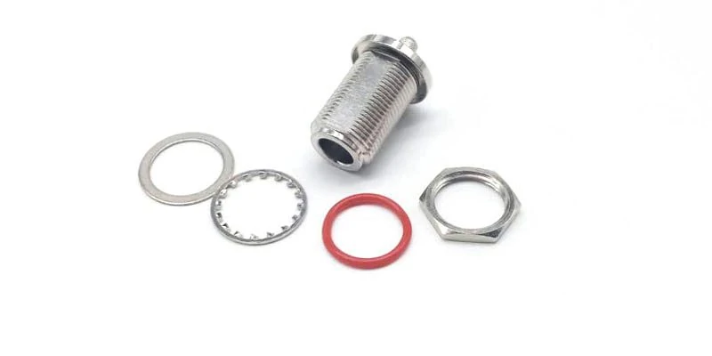
Exploded view of an N type female bulkhead connector with washer, locking washer, O-ring, and mounting nut, showing the components used for panel mounting and sealing.
A connector drawing should control the panel cutout. The product photo should not.
This sounds simple, but it is a frequent production problem. Two N female receptacles may share the same front interface while using different shoulders, flange dimensions, jam-nut positions, mounting holes, or panel thickness limits.
If purchasing approves a connector before mechanical engineering freezes the panel drawing, a later “equivalent” substitution can create an enclosure problem even when the RF interface remains correct.
Define the Cutout From the Exact Connector Drawing
For each fixed receptacle, verify at least:
- panel hole diameter
- flange dimensions
- mounting screw pattern
- jam-nut location
- washer stack
- connector shoulder position
- allowed panel thickness
- front- or rear-mount direction
Do not assume that another N-type receptacle with the same thread can use the same cutout.
A small dimensional change can move the mating reference plane outward, reduce thread engagement, or leave insufficient room for the washer and nut.
That is especially important when the enclosure drawing is already released to sheet-metal production.
Reserve Clearance for the Mating N Male Coupling Nut
The connector fitting through the panel is only half the problem.
The user must also be able to install the mating cable.
N-type male connectors use a relatively large coupling nut compared with compact RF interfaces such as SMA. On a dense front panel, neighboring ports, handles, heatsinks, switches, enclosure edges, or protective covers may block finger or tool access.
A port can therefore pass mechanical fit inspection and still be difficult to use.
Multi-port systems deserve particular attention. Cable bend radius and connector spacing should be checked with the actual mating cable, not only with bare connectors in CAD.
A thick feeder cable can need substantially more routing space than the connector body suggests.
Check Front-Mount and Rear-Mount Accessibility
Front-mount and rear-mount receptacles create different service conditions.
A rear-mounted connector may produce a clean exterior and protect the mounting hardware, but internal replacement can require access behind the panel. A front-mounted design may be easier to service but expose more hardware.
Neither method is automatically better.
The correct choice depends on:
| Design Question | Front-Mount Concern | Rear-Mount Concern |
| Installation | External hardware access | Internal assembly access |
| Replacement | Usually easier from outside | May require enclosure opening |
| Panel clearance | Check nut/flange spacing | Check internal shoulder clearance |
| Sealing | Verify gasket position | Verify panel interface and compression |
| Service tools | External wrench clearance | Internal tool clearance |
The useful comparison is not appearance. It is what happens during assembly and later service.
Which Rear-Side Connection Should Carry the RF Signal?
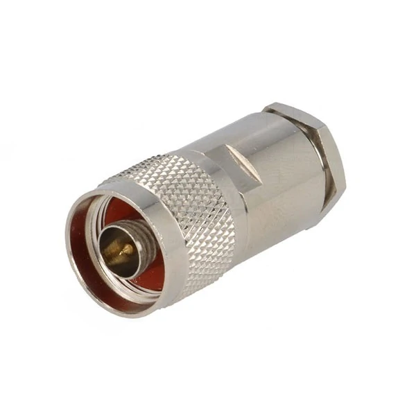
N type RF coaxial connector using a cable clamp termination structure, suitable for antenna cables, RF equipment connections, and coaxial cable assemblies.
Once the front panel is fixed, the next question is where the RF signal goes behind it.
The rear connection is often where a mechanically good enclosure turns into a poor RF assembly.
Use a Coax Tail When the RF Module Is Offset From the Panel
A short flexible coaxial assembly is often useful when the RF module does not align directly with the chassis port.
This arrangement separates panel mechanics from PCB mechanics.
It can absorb manufacturing tolerance, small alignment errors, vibration, and servicing movement without forcing the RF module to carry the external mating load.
It also gives the layout team more freedom when the RF board sits deeper inside the enclosure.
The trade-off is that the added cable and interfaces become part of the RF path. Their loss, return loss, termination quality, and routing must be included in qualification.
Use Direct PCB Connection Only When the Launch Is Engineered for It
A PCB pin on the back of the connector does not mean the complete launch will automatically meet the intended frequency.
The connector-to-board transition depends on:
- pad geometry
- reference plane
- ground via placement
- board stack-up
- connector height
- center-pin transition
- surrounding ground structure
A continuity test cannot verify this.
The assembly may show perfect DC continuity and still produce excessive reflection near the upper operating band.
For that reason, a direct PCB-mounted N receptacle should be treated as an RF launch design, not simply a mechanical mounting choice.
Evaluate Feedthrough Designs for Back-to-Back RF Access
A feedthrough structure can be useful when an RF connection is needed on both sides of an enclosure or partition.
But “female on the front” is still not enough information.
Confirm:
- interface on each side
- gender on each side
- impedance
- mounting method
- RF rating
- grounding arrangement
- sealing requirement
An N female-to-female feedthrough and an N female equipment receptacle can look similar in a catalog while serving very different mechanical roles.
Minimize Rigid Adapter Chains Behind the Panel
may be convenient during prototyping.
It is less attractive when the adapter chain becomes long, rigid, and unsupported.
Each interface adds another mechanical joint and another RF discontinuity. More importantly, a rigid chain can transfer panel movement directly to a smaller module connector.
Where space allows, a short flexible coax transition is often easier to support and service.
The SMA to N Adapter Guide is useful when a direct adapter is genuinely required, but an adapter should not be used simply because the rear architecture was never defined.
How Do You Prevent 50Ω and 75Ω Female-Port Errors?
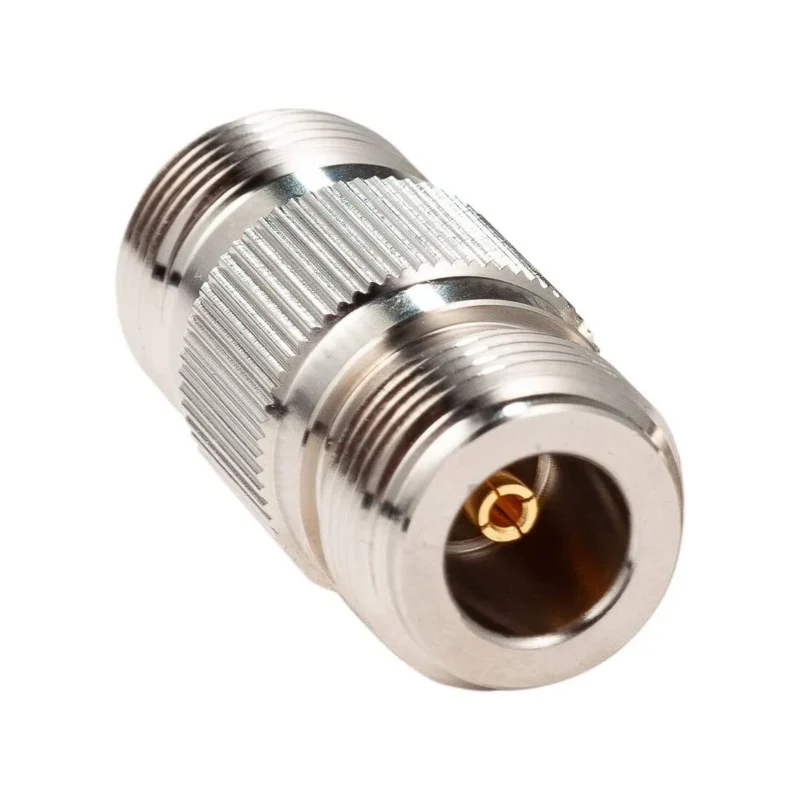
Mechanical compatibility does not confirm impedance compatibility.
N-type interfaces exist in both 50-ohm and 75-ohm versions. That means an engineer or buyer should not release a port solely because the thread, gender, and panel geometry appear correct.
Confirm the Port Impedance Before Mechanical Installation
Treat impedance as a hard gate in the design review.
The point is not that every part must merely be labeled with a number. The whole path should be designed around the same reference impedance.
Match the Mating N Male to the Same System
Do not qualify only the fixed female port.
The external cable assembly is part of the interface.
Its connector impedance, cable impedance, frequency range, termination quality, and mechanical loading should match the equipment port requirement.
This is another reason purchasing language such as “N female port required” is incomplete. The fixed connector may be correct while the final mating cable is not.
How Should Grounding, Sealing, and Structural Support Work Together?
A metal connector mounted to a metal enclosure is not automatically a verified chassis ground.
That assumption becomes risky when the enclosure uses paint, powder coating, anodizing, insulating washers, or sealing gaskets. The connector may be mechanically secure while the expected electrical bond is weak or inconsistent.
Define Whether the Connector Body Must Bond to Chassis Ground
First decide whether the N female connector body is intended to form part of the chassis-ground path.
If bonding is required, verify it in the finished assembly, not only on a bare connector.
Any insulating layer in that path can change the result.
Ground continuity testing is therefore useful after final installation, especially when the enclosure finish changes between prototype and production.
Separate RF Grounding From Environmental Sealing
A gasket, O-ring, or waterproof boot solves a different problem.
Sealing protects the interface from moisture, dust, or environmental exposure. It does not automatically guarantee a low-resistance chassis bond.
The design may need both:
- a controlled metal-to-metal bonding surface
- a separate sealing structure
Trying to make one component perform both functions without checking the final assembly can create inconsistent results.
Support the External Feeder Before It Loads the Port
Large coaxial cables can apply significant bending force to a panel connector.
The connector should not become the cable-support bracket.
Use cable clamps, strain relief, or chassis support where the external feeder is heavy, stiff, or routed with a tight bend near the enclosure.
This becomes more important in outdoor equipment, base-station hardware, test racks, and any installation where the cable weight remains on the port continuously.
When Should the N Female Port Transition to SMA?
An N interface is useful at the chassis boundary, but the internal RF module may use a much smaller connector.
This approach separates the large external interface from the compact electronics.
Use a Flexible Transition When Positions Do Not Align
A short internal coax cable can absorb:
- panel-to-PCB tolerance
- vibration
- servicing movement
- small alignment errors
- thermal movement
It also prevents mating torque from being transferred directly to a PCB-mounted SMA connector.
A rigid N-to-SMA adapter can still work when both sides are mechanically supported. The problem appears when the N side is fixed to the chassis and the SMA side is expected to support the entire adapter mechanically.
That may save one cable assembly, but it transfers stress directly into the smaller interface.
How Can You Release an N Female Equipment Port for Production?
Production release should require more than a connector part number.
A useful engineering review can treat the port as a defined system.
N Female Port Architecture Matrix
| Design Field | Production Check |
| Port role | Antenna, test, equipment, or feedthrough |
| Front interface | Verify mating N male |
| Impedance | Confirm 50Ω or 75Ω system |
| Mounting | Jam nut, flange, or bulkhead |
| Rear interface | Coax, PCB, solder, or feedthrough |
| Chassis ground | Bonded or isolated |
| Sealing | None, gasket, or O-ring |
| External cable load | Define strain relief |
| Internal transition | Direct, coax, or adapter |
| Frequency | Match actual operating band |
| RF acceptance | Define return loss / VSWR test |
| Serviceability | Replaceable or fixed |
| Change control | Freeze drawing revision |
This matrix is useful because it exposes incomplete specifications early.
That rule prevents purchasing from releasing a connector based only on gender and mounting appearance.
Female-Port Qualification Gate
This does not mean every project needs the same laboratory test depth. A low-frequency indoor assembly may require less qualification than a high-frequency outdoor radio.
The principle is that acceptance criteria should be defined before mass production.
How Should Purchasing Describe the Final N Female Configuration?
That description leaves too much room for interpretation.
Add the exact cable, PCB, sealing, plating, or environmental requirements when the project depends on them.
The drawing revision should also be frozen for repeat orders.
Otherwise, a later batch may still arrive as an “N female connector” while the flange size, thread length, rear interface, gasket, or mounting hardware has changed.
That kind of substitution can pass incoming visual inspection and still fail during enclosure assembly.
FAQ
Can an N female feedthrough replace an equipment receptacle?
Not automatically. The front interface may match, but the mounting method, rear connection, grounding, sealing, and mechanical support may be different.
Why can an N female port pass continuity but show poor return loss?
Continuity only confirms an electrical path. A poor PCB launch, damaged connector, incorrect impedance, rear cable termination, or mounting stress can still increase RF reflection.
Does mounting an N female connector to a metal chassis automatically ground it?
No. Paint, anodizing, coatings, gaskets, or insulating hardware can interrupt the intended bonding path. Verify ground continuity in the final assembly when chassis bonding is required.
Why should the mating N male cable be included in the design review?
The cable affects coupling clearance, bend radius, feeder weight, mating force, and load on the chassis port.