
The adapter fitted. The continuity test passed. Then the RF level changed every time the SMA cable moved.
That failure is easy to misdiagnose as a bad antenna or unstable device port. In practice, a rigid MCX to SMA adapter can create both an electrical transition and a mechanical lever. The connector names may be correct while the gender, center contact, impedance, body orientation, or installed load is wrong.
A rigid adapter works well when both interfaces are identified correctly, the SMA-side cable is supported, and the complete path is verified at the intended frequency. It becomes risky when buyers select from a product title alone or use a long adapter stack to solve an enclosure problem.
How Do You Identify the Exact MCX and SMA Mating Ends?
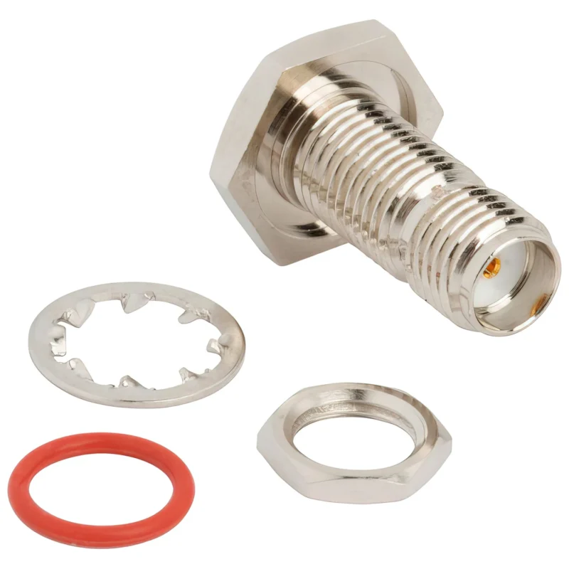
“MCX male to SMA female” sounds specific, but it may still be misunderstood. Connector descriptions sometimes use male and female to describe the body, while other listings appear to describe only the center contact. Reverse-polarity SMA adds another source of error.
Read each side as a complete interface:
- Connector family
- Plug or jack body
- Center pin or center socket
- Coupling method
- Standard or reverse polarity
- Device-side mating interface
The MCX side normally uses a snap-on coupling. The SMA side uses a threaded coupling. Those mechanical differences are easy to recognize, but they do not confirm the contact configuration or impedance.
An MCX male to SMA female adapter, for example, should not be approved until the drawing confirms what the supplier means by “MCX male.” A product photo showing the mating face is useful, but a controlled dimensional drawing is safer.
The IEC identifies IEC 61169-36 as the series specification for 50-ohm Type MCX snap-on RF connectors. It covers mating-face dimensions, gauging information and applicable tests, and the IEC product page currently lists a stability date of 2028.
Separate MCX from MMCX before ordering
MCX and MMCX are different interfaces. A small connector found on a board should not be classified by visual scale alone. Compare:
- Body diameter
- Snap-interface geometry
- Existing cable part number
- Equipment drawing
- Port photograph
- Manufacturer documentation
For a broader review of the connector family, use the MCX connector guide before approving the adapter interface.
A practical RFQ description follows a fixed order:
MCX End + SMA End + Body Style + Impedance + Frequency
Example:
MCX Plug to SMA Female Straight Adapter, 50 Ohm, DC–6 GHz
This sequence gives the supplier fewer opportunities to fill in missing details with assumptions.
When Is a Rigid Adapter Mechanically Safe?
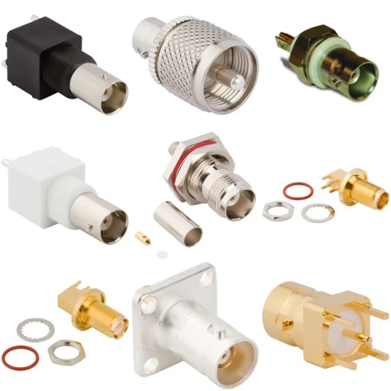
A rigid body is not automatically a bad choice. It is appropriate when the two connector axes are aligned and the attached SMA component does not place meaningful side load on the MCX port.
The safer conditions are straightforward:
- The equipment remains stationary.
- The connected SMA cable is short and flexible.
- The cable has independent strain relief.
- The MCX port is mechanically supported.
- The adapter has limited overhang.
- The connection will not be repeatedly bumped, rotated or serviced.
The problem begins when the rigid adapter becomes a handle for the external cable. A heavy coaxial lead, semi-rigid line, attenuator or additional elbow creates leverage. That leverage is transferred to the MCX snap interface and, for PCB-mounted jacks, potentially to the solder joints and board pads.
Continuity may remain normal during an initial bench inspection. The fault may appear only after vibration, enclosure installation or repeated cable movement.
Rigid Adapter Mechanical Risk Score
Use the following screening tool before approving a permanent installation. Score each factor from 0 to 3.
| Risk factor | 0 points | 1 point | 2 points | 3 points |
| Port alignment | Fully aligned | Minor offset | Visible offset | Forced alignment |
| Adapter overhang | Very short | Short | Moderate | Long stack |
| External cable stiffness | Very flexible | Flexible | Stiff | Semi-rigid or heavy |
| Cable support | Fully supported | Support nearby | Remote support | Unsupported |
| Equipment movement | Fixed | Occasional | Frequent | Continuous vibration |
| Service frequency | Rare | Monthly | Weekly | Daily |
| Main risk | Axial overhang | Side loading | Added interfaces | Cable loss and routing damage |
Mechanical Risk Score = Alignment + Overhang + Cable + Support + Movement + Service
Interpret the result as a design-screening guide:
- 0–5: The rigid adapter is usually reasonable.
- 6–10: Add cable support and inspect the installed load.
- 11–14: A flexible adapter cable is normally safer.
- 15–18: Do not load the board-mounted MCX port directly.
This score does not replace a device manufacturer’s connector-load specification. Its purpose is to expose installations that appear simple but contain several moderate risks at the same time.
How Should 50-Ohm and 75-Ohm Compatibility Be Checked?
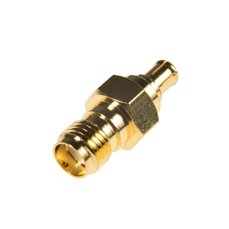
Mechanical mating and electrical compatibility are separate decisions.
The full signal path may include:
- Device MCX port
- MCX side of the adapter
- Internal adapter transition
- SMA interface
- SMA coaxial cable
- Antenna, receiver or test instrument
Each item should have a known nominal impedance.
Do not infer impedance from the words “MCX” or “SMA” alone. Procurement documents should state 50-ohm MCX to SMA adapter when that is the requirement. When a device uses a 75-ohm MCX-related interface, the buyer must confirm both mating geometry and electrical design rather than assuming a standard 50-ohm SMA conversion is acceptable.
A connector can physically mate while creating an impedance discontinuity. The likely consequence is degraded return loss, particularly as operating frequency increases. The amount of degradation depends on the complete transition, not just the impedance label.
Use this decision sequence:
- Is the device MCX port specified as 50 ohms?
- Yes: continue.
- Unknown: obtain the drawing or datasheet.
- No: do not approve a standard 50-ohm conversion automatically.
- Is the connected SMA system 50 ohms?
- Yes: continue.
- No: review the entire RF architecture.
- Does the adapter datasheet state the same impedance?
- Yes: continue.
- No or unspecified: request verification.
- Are insertion loss and return loss defined across the full operating band?
- Yes: proceed to first-article testing.
- No: add project-specific acceptance limits.
Which Body Style Fits the Available Space?
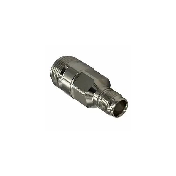
Straight MCX to SMA adapter used to connect an MCX device port to an SMA coaxial cable or RF component. Connector gender, impedance, frequency range and installed cable load should be verified before use.
Straight adapters are useful when both connector axes line up and the equipment provides enough rear clearance. They are common in open bench setups, temporary testing and compact antenna connections where the SMA-side load is light.
A right-angle MCX to SMAadapter changes the cable exit direction. It may solve an enclosure-clearance problem, but it does not automatically reduce connector stress.
The right-angle body must be evaluated in its installed orientation. Check whether the cable exits toward the PCB, enclosure wall or another component. Also check whether tightening or moving the SMA cable rotates the MCX side.
A right-angle adapter can reduce axial projection but increase the bending moment if the attached cable hangs from the side. Evaluate the real cable direction, not the adapter by itself.
Avoid correcting geometry with stacked components such as an MCX-to-SMA adapter, SMA gender changer and SMA elbow. Each extra interface adds length, another contact pair and another opportunity for looseness or mismatch.
How Much RF Error Can One Adapter Add?
An insertion-loss value without a reference path can be misleading. Test the adapter as a change to a known setup rather than treating the complete measured path as adapter loss.
A practical comparison procedure is:
- Define the calibration or reference planes.
- Inspect and clean the test interfaces.
- Measure the reference through path.
- Insert the MCX-to-SMA adapter.
- Repeat the same frequency sweep.
- Compare the traces without replacing unrelated cables.
Calculate the adapter-added loss as:
ΔIL(f) = ILadapter path(f) − ILreference path(f)
Record the result at the start frequency, important application bands, stop frequency and worst-case point.
A single number measured at 100 MHz is not enough for an adapter intended for several gigahertz. Resonance, contact geometry and fixture repeatability may make the worst result appear near the upper band or at a narrow intermediate frequency.
Return loss should be checked from both directions where the setup allows it. Record S11, S22, the worst return-loss point and the frequency at which it occurs.
IEC 61169-1 provides the general RF connector framework for terminology, ratings and electrical, mechanical and climatic measuring procedures. The IEC describes its methods as a basis for acceptance and type-approval testing, and currently lists a stability date of 2028.
Do not confuse connection repeatability with stable performance
Repeat the measurement after:
- First mating
- Third mating
- Fifth mating
- Cleaning
- Reinstalling the adapter
- Repositioning the SMA cable
A part that passes once but shifts significantly after remating needs further investigation. The change may come from contamination, center-contact condition, inconsistent snap engagement or mechanical loading from the cable.
Protect the MCX Port During Installation
The installation sequence should prevent cable weight and tightening torque from reaching the MCX interface.
Where the equipment layout allows it:
- Connect the SMA cable to the adapter.
- Support the cable weight.
- Align the MCX mating interfaces.
- Push the MCX connection straight into place.
- Confirm complete snap engagement.
- Install permanent strain relief.
If the MCX side must be connected first, hold the adapter body while tightening the SMA coupling. Do not let the complete adapter rotate against the board-mounted port.
Removal also matters. Pull along the connector axis. Do not disconnect the adapter by pulling the cable, rocking the body from side to side or twisting it as though the MCX coupling were threaded.
A cable clip, enclosure clamp, adhesive tie mount, fixture bracket or short service loop can keep external motion away from the snap interface.
Installation acceptance card
Record the following before releasing the assembly:
- Port inspected
- Correct adapter confirmed
- SMA cable preconnected or supported
- MCX axes aligned
- Full engagement verified
- Cable strain relief installed
- Cable movement checked
- RF verification completed
- Installer and date recorded
This small record is useful when failures appear only after final assembly. It shows whether the adapter was evaluated in the installed state rather than only on an open bench.
How Should the Adapter Be Tested Before Release?
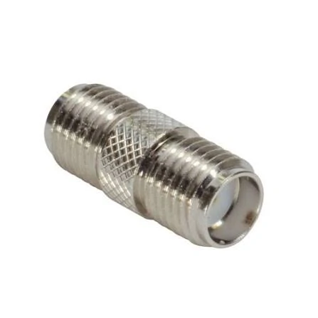
SMA female-to-female coaxial adapter shown as an example of an additional interface that may be used with an MCX to SMA adapter. Stacked adapters increase overall length and can introduce extra insertion loss, mismatch and mechanical leverage.
Start with mechanical fit. RF testing should not be used to approve a visibly forced or unstable installation.
Inspect:
- Snap engagement and retention
- Connector concentricity
- Center-contact position
- SMA thread condition
- Enclosure interference
- Wrench access
- Adapter-body movement
- Visible load on the PCB port
Then separate DC checks from RF checks.
DC checks include center-conductor continuity, outer-conductor continuity and center-to-body isolation. A gentle movement test may expose intermittent contact, but it must not apply enough force to damage the connector.
RF checks include full-band S21, S11, S22, reconnection repeatability and installed-state response. Where the product will operate under motion, compare the stable and movement-sensitive results using a controlled fixture.
A first-article record should identify:
- Adapter part number
- Drawing revision
- MCX and SMA interfaces
- Impedance
- Frequency range
- Maximum insertion-loss result
- Minimum return-loss result
- Test fixture IDs
- Calibration date
- Mechanical-fit status
- Installed-state result
- Approval status
Do not approve production from a generic catalogue description when the application depends on an exact interface or upper-band RF limit.
When Should the Rigid Body Give Way to an Adapter Cable?
Use a flexible transition when alignment cannot be controlled or when movement is part of normal operation.
Typical cases include:
- Offset equipment ports
- Vehicle vibration
- Moving machinery
- Heavy antenna cables
- Restricted enclosure geometry
- Frequent servicing
- Fragile PCB-mounted MCX jacks
The flexible alternative may be described as an MCX to SMAadapter cable, MCX-to-SMA pigtail or MCX-to-SMA cable assembly. It adds cable length and therefore more attenuation, but it can isolate the device port from side load and provide routing freedom.
The existing MCX to SMA cable selection and routing guide covers flexible cable choice, RG316, cable length, loss and strain relief in more detail. Those topics should not be confused with rigid-adapter integration.
Compare the complete connection structures:
Rigid arrangement
Device MCX port → rigid adapter → separate SMA cable
Flexible arrangement
Device MCX port → MCX-to-SMA cable assembly → external SMA interface
The rigid arrangement minimizes electrical length, but it creates a rigid load path. The flexible assembly adds coaxial cable but reduces alignment sensitivity.
For other miniature interface combinations, the SMA adapter cable guide provides a broader comparison.
Build a Supplier-Ready Adapter Specification
A supplier cannot verify details that were never written into the RFQ.
At minimum, define:
Interface
- MCX plug or jack
- SMA male or female
- Standard or reverse-polarity SMA
- Device-side mating connector
Electrical requirements
- Nominal impedance
- Operating frequency range
- Maximum insertion loss
- Minimum return loss or maximum VSWR
- Power requirement
- Contact resistance
- Insulation resistance
Mechanical and environmental requirements
- Straight or right-angle body
- Maximum overall length
- Maximum body diameter
- Wrench-flat dimensions
- Retention requirement
- Expected mating cycles
- Operating temperature
- Body and contact plating
- Environmental exposure
Documentation
- Controlled dimensional drawing
- Certificate of conformity
- Material declaration
- VNA plot or data file
- First-article inspection report
- Lot traceability
- Packaging and protective-cap requirements
A useful BOM line might read:
MCX plug to SMA female straight RF adapter, standard polarity, 50 ohms, DC–6 GHz, maximum insertion loss and VSWR per approved drawing, gold-plated center contacts, controlled overall length, first-article VNA verification required.
That is far more useful than “MCX SMA adapter.”
For projects that are still comparing connector families, use the RF connector selection guide before locking the BOM.
How Should Incoming Lots Be Accepted?
Visual interface checks should normally cover the full lot because incorrect gender, damaged threads and bent center contacts are inexpensive to detect before assembly.
Use higher RF sampling for:
- New suppliers
- New drawing revisions
- New machining or plating processes
- Higher frequency requirements
- Previous failed lots
- Customer returns
- Long production interruptions
- Changes between straight and right-angle construction
| Inspection item | Method | Suggested coverage | Acceptance basis | Failure action |
| Interface identity | Visual and drawing comparison | 100% | Approved drawing | Quarantine |
| Center contact | Magnified inspection | 100% or defined sample | No deformation or damage | Sort and investigate |
| SMA threads | Visual and mating gauge | 100% or sample | Smooth engagement | Sort |
| Snap retention | Controlled mating fixture | Defined sample | Project requirement | Expand inspection |
| Continuity and isolation | Electrical test | Defined production plan | Pass | Reject or sort |
| Insertion loss | VNA sweep | Risk-based sample | RFQ limit | Stop release |
| Return loss | VNA sweep | Risk-based sample | RFQ limit | Investigate lot |
| Installed fit | Device fixture | First article or each lot | No interference or forced alignment | Rework or reject |
| Packaging | Visual | 100% | Caps and protection present | Repack |
One failed RF sample should not be ignored or immediately blamed on measurement variation. Stop lot release, verify calibration, retest the same unit and test additional samples. Inspect interface dimensions and review machining, plating and assembly records before deciding whether to sort, rework or reject the lot.
Diagnose Failures Before Replacing the Whole RF Path
Suspect the adapter or its mechanical integration when the signal changes immediately as the SMA cable is touched.
Common symptoms include:
- Signal variation when the cable turns
- Connection drop when the adapter moves
- Different results after remating
- Weak or inconsistent MCX retention
- Stable SMA thread engagement but unstable RF response
Use controlled substitution rather than replacing every component at once:
- Inspect all mating interfaces.
- Test with a known-good antenna.
- Test with a known-good SMA cable.
- Replace only the adapter.
- Measure the device port directly where practical.
- Compare free-state and installed-state results.
Record the adapter orientation, cable position, movement direction and signal change. A repeatable change caused by one movement is more useful diagnostically than a general note saying “signal unstable.”
Replace the adapter when it shows:
- Reduced snap retention
- Damaged or loose center contact
- Cracked or displaced dielectric
- Persistent contamination
- SMA thread damage
- Excessive insertion loss
- Return-loss failure
- Reconnection drift beyond the project limit
Do not keep an intermittent adapter in service because it passes continuity when untouched.
FAQ
Can a rigid MCX to SMA adapter damage a PCB-mounted MCX port?
Yes. The risk depends on adapter overhang, external cable weight, cable stiffness, port support and equipment movement. A long rigid adapter attached to a heavy SMA cable can transfer side load and torque to the MCX jack, solder joints or PCB pads. Support the cable independently or replace the rigid connection with a flexible adapter cable.
Can a 75-ohm MCX interface connect to a 50-ohm SMA adapter?
Do not approve it from appearance alone. Confirm the device interface, adapter design and mating dimensions from controlled documentation. Even where the connectors can be mechanically joined, the impedance transition may degrade return loss. Test the complete path across its intended frequency range before release.
Why does the RF signal change when the SMA cable is rotated?
Cable rotation can transfer torque through the rigid adapter to the MCX snap interface. It may also alter cable bending or contact pressure. Hold the adapter body, support the cable and compare S-parameters before and after controlled movement. A repeatable change usually indicates a mechanical-contact or cable-routing issue.
Does a right-angle MCX to SMA adapter always reduce stress?
No. It reduces axial clearance, but it may redirect cable weight into a side load. The result depends on the adapter orientation, cable exit direction, stiffness and strain relief. Evaluate the complete installed geometry rather than assuming that a right-angle body is mechanically safer.
Should the SMA cable or MCX side be connected first?
Where practical, connect the SMA cable to the adapter first, support its weight and then engage the MCX side along the connector axis. If the MCX side must be installed first, hold the adapter body while tightening the SMA connection so that torque is not transferred to the device port.
How can you tell whether the adapter or antenna is causing signal loss?
Use known-good components and change only one item at a time. Keep the device, frequency, test position and measurement setup unchanged. If the result returns to normal only after replacing the adapter, inspect its contact condition and verify insertion loss, return loss and reconnection repeatability.
When should an MCX to SMA adapter be replaced?
Replace it when snap retention declines, the center contact is damaged, the dielectric is cracked, the SMA threads are worn, cleaning does not restore stable contact, or measured insertion loss and return loss exceed the project limits. An adapter that changes response after normal remating should not remain in a controlled RF path.
A rigid MCX-to-SMA transition is a small component, but it should not be treated as an undefined accessory. Specify both interfaces, impedance, frequency, body geometry and test limits. Then inspect it in the actual installed configuration.
For a custom or production MCX to SMA adapter, send the mating-interface drawings, required frequency, impedance, maximum dimensions, expected cable load and RF acceptance limits before ordering. Those details make it possible to verify whether a rigid adapter is appropriate or whether a flexible transition will reduce integration risk.
