
A cable assembly can pass continuity testing and still fail in a microwave measurement setup.
This usually appears when a project moves from a short bench sample to a real test environment. The connector mates correctly, the cable looks similar to the drawing, and the first measurement seems acceptable. Problems often appear later when frequency increases, adapters are added, the cable is bent repeatedly, or the measurement system requires better repeatability.
For engineers working with microwave test equipment, the connector interface is only one part of the RF path. The cable type, machining accuracy, mating condition, and calibration method all influence the final result.
The key question is not simply whether a connector supports a certain frequency.
The real question is whether the complete RF assembly can maintain the expected electrical performance in the actual application.
How Does a K Connector Support High-Frequency RF Testing?
This image shows the interface structure of a 2.92mm K connector. Precision manufacturing is essential for maintaining impedance control, reducing signal reflection, and ensuring stable performance in microwave RF systems.
The K connector was developed for applications where traditional RF connectors began reaching their practical limits. Its 2.92mm interface provides a smaller precision structure compared with many general-purpose RF connectors while maintaining compatibility with common microwave measurement environments.
In RF testing, small mechanical differences become electrical problems.
The diameter of the center conductor, dielectric spacing, contact alignment, and machining tolerance all affect how electromagnetic energy travels through the connector interface.
At lower frequencies, small mechanical variations may have limited impact.
Why Do Engineers Use 2.92mm Connectors in Microwave Measurement Systems?
Typical applications include:
| Application | Why K Connector Is Used |
| VNA calibration | Supports repeatable microwave measurements |
| RF test fixtures | Provides precision interface connection |
| Microwave modules | Suitable for compact high-frequency designs |
| Cable assemblies | Used for flexible microwave test connections |
A K connector is not automatically a better choice simply because it supports a higher frequency range.
The complete assembly still depends on:
- connector design
- cable construction
- termination quality
- insertion loss
- VSWR performance
- test requirements
A 2.92mm cable assembly with a suitable microwave cable may perform well in a laboratory test system. The same connector mounted on a lower-performance cable may become the limiting factor.
How Does Connector Geometry Affect RF Performance Above GHz Frequencies?
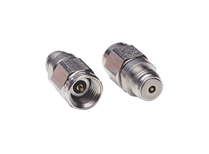
This image shows a 2.92mm K connector microwave RF adapter used in high-frequency testing applications. The K connector interface is commonly applied in VNA calibration systems, microwave modules, RF test fixtures, and precision cable assemblies requiring reliable signal transmission.
Microwave connectors are precision mechanical components.
Unlike many low-frequency connections where physical dimensions are less sensitive, microwave interfaces require accurate control of the RF transition.
Important mechanical factors include:
- center contact alignment
- dielectric position
- connector face condition
- thread accuracy
- machining tolerance
A small offset at the mating interface can change the impedance transition.
This can increase reflection and affect measurements such as:
- S11
- S21
- VSWR
- return loss
For this reason, visual similarity between connectors does not guarantee electrical compatibility.
Two connectors may look almost identical but behave differently when used in a high-frequency test system.
How Do You Identify a 2.92mm K Connector Interface?
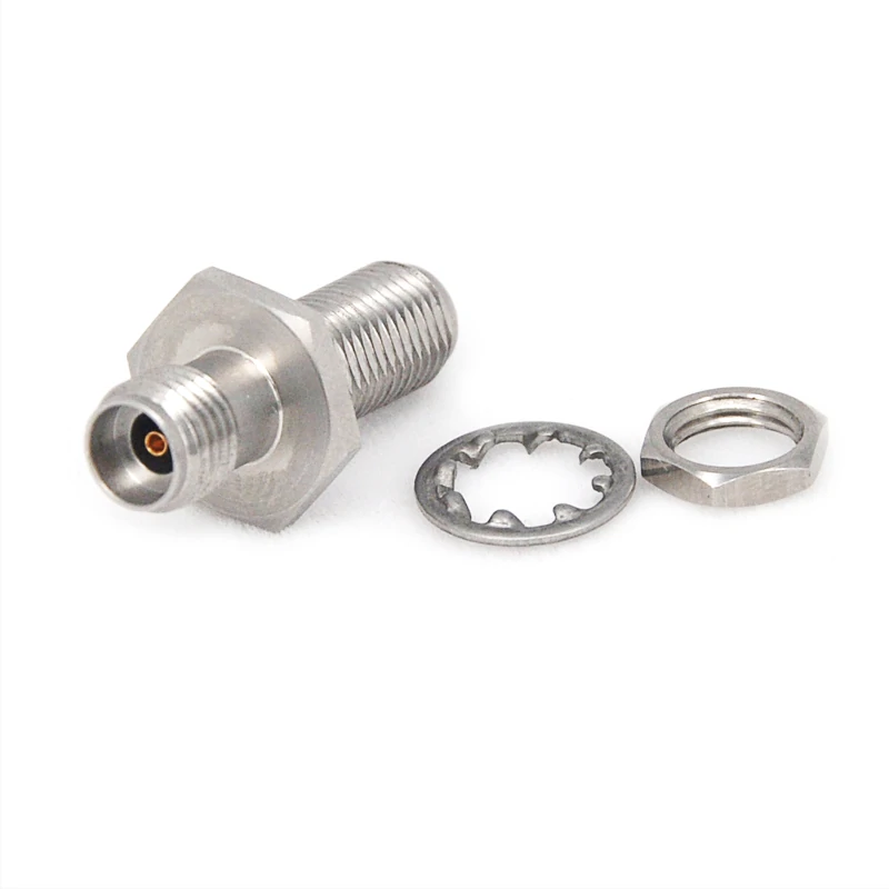
This image shows a 2.92mm K connector cable assembly used for microwave RF testing. These assemblies are commonly applied in VNA systems, laboratory measurements, communication equipment testing, and high-frequency applications requiring accurate signal transmission.
A common sourcing mistake is selecting a connector by appearance alone.
K connectors, SMA connectors, and 3.5mm connectors can look very similar. However, their mechanical interface design and intended performance range are different.
Before ordering a cable assembly or adapter, engineers should confirm several details.
Check the Interface Before Connecting Test Equipment
The basic inspection points include:
| Check Item | Reason |
| Connector gender | Prevent male/female mismatch |
| Thread type | Confirm mechanical compatibility |
| Center contact structure | Verify correct interface |
| Interface standard | Avoid incorrect substitution |
A 2.92mm male connector and 2.92mm female connector must be correctly matched with the equipment port or adapter.
For production purchasing, the connector description should not only include “K connector”.
A clearer specification should include:
- interface type: 2.92mm / K
- gender: male or female
- impedance: 50 ohm
- frequency requirement
- cable type
- cable length
- termination method
This information reduces mistakes during RF cable assembly sourcing.
Why Should K Connectors Not Be Confused With SMA and 3.5mm Interfaces?
Comparison of different RF connector interfaces including K connector, SMA, and 3.5mm connector types. Proper connector selection helps avoid performance issues caused by interface mismatch or unsuitable frequency capability.
The biggest confusion comes from physical similarity.
SMA connectors are widely used in RF systems and many engineers already have SMA-based equipment. However, a K connector is normally selected when microwave measurement requirements become more demanding.
A simple comparison:
| Connector | Typical Use | Engineering Focus |
| SMA | General RF modules and systems | Compact RF connection |
| K (2.92mm) | Microwave testing | Precision measurement |
| 3.5mm | Laboratory microwave systems | Higher precision applications |
| 2.4mm | mmWave applications | Higher-frequency interfaces |
Mechanical connection does not always mean equivalent RF performance.
A connector may physically mate with another interface while still creating limitations in frequency range, calibration accuracy, or measurement repeatability.
For engineers purchasing RF components, the correct approach is to verify the complete RF requirement instead of selecting a connector based only on external appearance.
How Does a K Connector Compare With SMA and 3.5mm Interfaces?
Selecting between K connector, SMA, and 3.5mm interfaces is not only a frequency decision. Engineers also need to consider existing equipment, calibration requirements, cable availability, and the repeatability expected from the measurement system.
A common mistake during RF sourcing is replacing a microwave connector with a visually similar connector without checking the complete RF path.
The connector may fit mechanically, but the measurement result may change.
For laboratory applications, the interface standard should match the purpose of the system.
How Does a K Connector Compare With SMA When Frequency Capability Matters?
SMA connectors are widely used across RF applications because they are compact, reliable, and available in many cable assembly configurations.
They are commonly found in:
- wireless modules
- antenna systems
- RF evaluation boards
- communication equipment
However, when testing requirements move toward microwave frequencies, engineers often consider a K connector.
The main difference is the precision of the interface design.
| Parameter | SMA Connector | K Connector (2.92mm) |
| Typical Application | General RF connection | Microwave testing |
| Interface Size | 3.5mm outer diameter interface family | 2.92mm precision interface |
| Frequency Capability | Depends on design | Commonly used for microwave applications |
| Main Advantage | Wide availability | Better suited for precision measurement |
| Common Use | RF modules, antennas | VNA, test fixtures, microwave assemblies |
The choice depends on the application.
A standard RF module may not require a K connector. Using a higher-frequency connector in a lower-frequency application can increase cost without improving the system.
On the other hand, a test cable operating close to the upper frequency limit of an SMA design may introduce unnecessary measurement uncertainty.
For VNA cables and microwave test fixtures, K connectors are often selected because repeatability becomes more important than simple connection.
When Should You Compare K Connector With a 3.5mm Connector?
The K connector and 3.5mm connector are often compared because both are used in precision microwave environments. In that situation, maintaining the same interface standard can simplify testing.
For new designs, engineers may evaluate:
- required frequency margin
- connector availability
- adapter requirements
- cable assembly options
- calibration compatibility
An adapter can solve a mechanical connection problem, but every additional transition may introduce another RF discontinuity.
A test setup with multiple adapters should always be evaluated as a complete system.
How Does a K Connector Compare With a 2.4mm Connector in mmWave Applications?
The 2.4mm connector is generally associated with higher-frequency microwave and mmWave applications.
Compared with a K connector, the 2.4mm interface uses a smaller contact structure and is designed for more demanding high-frequency environments.
A simple selection reference:
| Application Requirement | Suitable Direction |
| General microwave measurement | K connector |
| Flexible microwave test cable | K connector |
| Higher-frequency mmWave testing | 2.4mm connector |
| Existing SMA equipment | SMA or SMA-compatible solutions |
| Mixed interface system | Consider precision adapters |
The important point is that frequency rating alone should not determine the connector choice.
A higher-frequency connector does not automatically improve a system operating at a lower frequency.
The cable, termination process, connector quality, and measurement method still affect the final RF performance.
How Should You Select a K Connector Cable Assembly?
A K connector cable assembly is a complete RF component, not just a connector attached to a cable.
During purchasing, engineers should define the full assembly requirement.
A common sourcing description such as:
“2.92mm cable”
is usually not enough.
The supplier should understand:
- connector gender
- cable structure
- operating frequency
- cable length
- insertion loss requirement
- flexibility requirement
- application environment
How Do You Match the Cable Assembly With Frequency and Loss Requirements?
The connector interface and cable type must work together.
A microwave assembly may use different cable structures depending on the application.
Flexible cables are convenient for laboratory movement.
Semi-rigid cables may provide better mechanical stability in fixed installations.
The selection should consider:
| Parameter | Why It Matters |
| Cable type | Determines flexibility and loss characteristics |
| Length | Longer cables usually increase attenuation |
| Frequency range | Ensures operation within specification |
| Insertion loss | Affects available signal level |
| Phase stability | Important for repeated measurements |
For VNA testing, cable stability can become as important as connector frequency capability.
A cable that moves during measurement may change phase behavior and affect repeatability.
How Does Frequency Range Affect K Connector Performance?
A K connector specification is often associated with a frequency value, but the number alone does not define the actual performance of the complete RF assembly.
A connector marked for microwave operation may still produce different results depending on:
- connector design
- machining accuracy
- cable selection
- assembly process
- test method
- calibration condition
For engineers purchasing RF components, the frequency rating should be treated as a starting point rather than the only selection requirement.
Why Should You Check the Verified Frequency Specification Instead of the Connector Name?
The term “K connector” generally refers to a 2.92mm interface standard, but different suppliers may offer different performance levels.
Two products with the same interface may have differences in:
- bandwidth
- VSWR
- return loss
- insertion loss
- mechanical repeatability
A cable assembly designed for a microwave test system should be evaluated based on the complete operating range.
For example, a project requiring operation near 40 GHz should confirm:
- actual tested frequency range
- cable attenuation at the target frequency
- connector VSWR specification
- measurement method
- production inspection process
The connector interface provides the mechanical transition. The final RF performance comes from the complete assembly.
How Does Calibration Quality Affect Microwave Connector Measurements?
A K connector is frequently used in VNA measurement environments where calibration accuracy directly affects the result.
Before testing a microwave assembly, engineers usually need to consider:
- calibration method
- reference plane position
- connector condition
- adapter influence
- cable movement
A connector that appears visually clean may still affect measurement stability if the mating surface has:
- dust contamination
- mechanical damage
- incorrect tightening
- excessive mating cycles
In precision RF testing, connector handling is part of the measurement process.
The test system and the connector interface work together.
How Can You Evaluate Insertion Loss and Reflection Performance?
| Measurement Item | Purpose |
| S11 | Evaluate reflected signal |
| S21 | Measure transmission characteristics |
| VSWR | Check impedance matching condition |
| Return Loss | Evaluate reflection level |
| Insertion Loss | Measure signal loss through the assembly |
A continuity test only confirms that the electrical path is connected.
It does not confirm microwave performance.
This is a common mistake during RF sourcing. A cable assembly may pass a basic electrical check but fail when tested at the target frequency.
How Can You Test a K Connector Assembly Before Deployment?
Before installing a K connector assembly into a production system, a basic inspection process can prevent many avoidable problems.
Microwave components require more attention than standard low-frequency cables because small mechanical issues may affect measurement results.
How Do You Validate K Connectors With VNA Testing?
For microwave applications, VNA testing provides a more complete evaluation of the assembly.
Typical measurements include:
- S-parameter testing
- insertion loss measurement
- return loss measurement
- VSWR verification
A suitable test setup should consider:
- correct calibration kit
- proper torque
- clean connector interface
- stable cable position
A measurement result is only meaningful when the test conditions are controlled.
Why Should Repeat Mating Tests Be Considered?
Some RF assemblies are connected once and installed permanently.
Others are used as test cables and may experience hundreds or thousands of connection cycles.
For frequently used microwave cables, engineers should consider:
- connector durability
- mating repeatability
- phase stability
- mechanical wear
A connector that performs well during the first test may require additional verification for long-term laboratory use.
K Connector RF Acceptance Checklist
| Item | Record |
| Connector Type | K / 2.92mm |
| Gender | Male / Female |
| Frequency Range | GHz |
| S11 | dB |
| S21 | dB |
| VSWR | Value |
| Connector Inspection | Pass / Fail |
| Calibration Status | Record |
| Re-mate Test | Pass / Fail |
| Final Result | Accept / Reject |
This checklist helps standardize incoming inspection and supplier communication.
For RF procurement teams, recording test conditions is especially useful when multiple suppliers provide similar-looking microwave assemblies.
When Should You Use a K Connector Instead of Another RF Interface?
A K connector is not required for every RF application.
The correct choice depends on the system requirement.
The complete RF path still determines the final result.
How Do You Specify the Right K Connector for a Project?
A clear specification prevents incorrect sourcing.
Instead of requesting only:
“Need K connector cable”
a better request includes complete assembly information.
K Connector Specification Checklist
| Parameter | Example |
| Interface | 2.92mm / K |
| Gender | Male / Female |
| Frequency Range | DC–40GHz |
| Cable Type | Flexible / Semi-rigid |
| Length | Custom |
| VSWR | Requirement |
| Insertion Loss | Requirement |
| Application | VNA / Test / Module |
A complete specification helps suppliers confirm whether the assembly matches the actual RF requirement.
How Can Engineers Create a Clear RF Requirement Statement?
A practical specification example:
2.92mm K male cable assembly, DC–40GHz, low VSWR, flexible microwave test cable for VNA measurement.
This type of description provides enough information for engineering review.
The final selection should consider:
- frequency margin
- measurement accuracy
- interface compatibility
- cable characteristics
- project budget
FAQ
Is a K connector the same as a 2.92mm connector?
In most RF applications, K connector and 2.92mm connector refer to the same interface family. However, different suppliers may offer different frequency ratings, mechanical tolerances, and assembly quality.
Does a 40GHz K connector cable always perform at 40GHz?
Not necessarily. The final performance depends on cable design, assembly quality, calibration condition, VSWR, and insertion loss.
Can a K connector cable assembly be used directly for VNA testing?
Yes, but the complete cable assembly should match the VNA system requirements before testing. A K connector only defines the interface type. .
Why can a K connector assembly fail even if it passes continuity testing?
A continuity test only confirms that the electrical path is connected. It does not measure microwave behavior. Problems such as poor contact alignment, cable performance limits, incorrect assembly, high VSWR, or excessive adapter transitions may only appear during RF measurements at higher frequencies
What is the difference between a K connector and a 2.92mm connector?
In most RF applications, these two names describe the same connector interface. The term K connector is commonly used in microwave testing environments, while 2.92mm describes the physical interface size. When selecting a product, engineers should still check the actual frequency range, VSWR specification, machining accuracy, and cable assembly quality because different suppliers may offer different performance levels.
