
A fuse replacement can look simple until the holder becomes the weak part of the assembly.
The fuse fits. The cap closes. Continuity passes. Then the equipment returns with a warm panel, a loose clip, or a fuse that cannot be removed after the enclosure is fully assembled. That is usually not a fuse-selection problem alone. It is a fuse holder selection problem, and it often starts with treating the holder as a generic accessory instead of a rated electrical and mechanical component.
A good fuse holder decision starts before the buyer compares catalog photos. The fuse body, circuit rating, mounting method, service access, and temperature environment all have to agree.
How do you match the fuse before choosing the holder style?
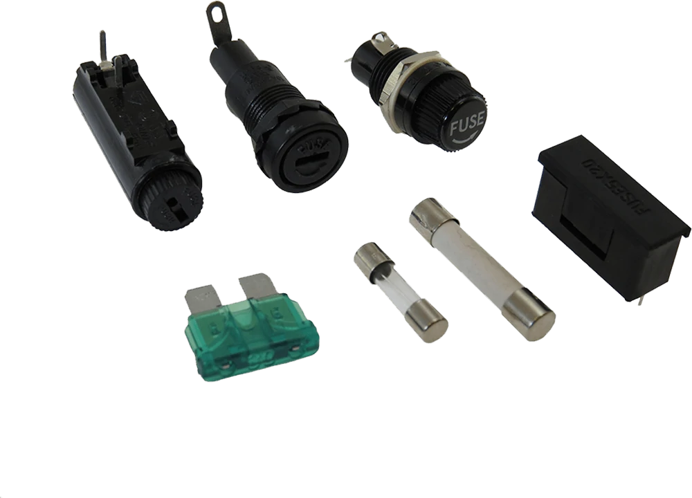
This image shows common fuse holder structures used in electronic and electrical applications, including panel mount fuse holders and PCB fuse holders. Selecting the correct holder requires matching fuse size, current rating, voltage rating, mounting method, and service access requirements.
Start with the fuse, not the holder.
That sounds obvious, but many sourcing errors happen because a buyer searches for a cartridge fuse holder, sees a similar cylindrical layout, and assumes it will work. A holder that accepts a glass tube fuse may still be wrong for the current, voltage, contact pressure, panel thickness, PCB footprint, or replacement method.
The first line of the BOM should identify the fuse clearly enough that another buyer can order the same fuse family without guessing. Record the fuse diameter, length, end-cap style, current rating, voltage rating, body construction, and whether the fuse must be replaced by the user or only by service staff.
If the fuse itself has not been selected yet, finish that step first. For applications still comparing fuse body styles, it is better to select the cartridge fuse before specifying its holder than to force the circuit into a holder footprint too early.
Start with the exact fuse body rather than the holder catalog photo
A 5×20 mm fuse, a 6.3×32 mm fuse, and other tube fuse formats may all look similar in small product images. They are not interchangeable unless the holder drawing and rating confirm it.
Physical fit does not prove electrical or thermal compatibility.
A fuse can snap firmly into the contacts and still run too hot. It can also meet the current requirement but fail the voltage, insulation, or accessibility requirement. This is why the holder should be treated as part of the protection system, not as a passive piece of plastic and metal.
Separate physical fit from electrical suitability
A glass fuse holder and a ceramic fuse holder may accept the same nominal fuse size, but that does not make the final installation equivalent.
Glass and ceramic construction affect visibility, breaking behavior, heat tolerance, and application choice. The holder decision still has to begin with exact dimensions and ratings. If the installed fuse is glass, the holder should not be chosen only because the fuse is transparent. If the installed fuse is ceramic, the holder is not automatically suitable for higher-energy use unless the holder, wiring, terminals, PCB spacing, and enclosure are also rated for the job.
For equipment using small glass cartridge fuses, match the holder to a glass cartridge fuse by checking both the fuse body and the installed holder path.
A useful approval note is simple:
Fuse body: 5×20 mm glass cartridge fuse. Holder: panel mount fuse holder for 5×20 mm fuse, rated for circuit voltage/current, with approved panel cutout and external replacement access.
That is much clearer than:
Fuse holder for glass fuse.
The second version invites substitution.
Keep the replacement path visible during design
A holder can pass the drawing review and still fail in service if the fuse cannot be removed.
This happens in compact equipment. The board is correct. The fuse fits. Then a connector, transformer, cover, cable harness, or heat sink blocks the extraction angle. For PCB fuse holders and fuse clips, reserve the hand or tool clearance before the layout is released. For a panel mount fuse holder, check rear terminal clearance and cap rotation after the wires are attached.
A good fit card should include more than size:
| Mechanical Field | Requirement |
| Fuse size | 5×20 mm, 6.3×32 mm, or exact approved size |
| Contact spacing | From holder drawing |
| Clip / carrier style | Open clip, covered PCB holder, or removable carrier |
| Fuse extraction clearance | Confirm after enclosure assembly |
| Adjacent component clearance | Confirm against final layout |
| Cover height | Check assembled condition |
| PCB / panel cutout | Match approved drawing |
| Service tool required? | Yes / No |
| Fit approval | PASS / HOLD |
Do not leave this check until pilot production. By then, the holder may already be locked into the enclosure tooling or PCB layout.
Which mounting method fits the service strategy?
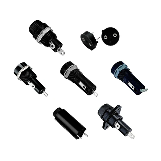
This image shows a PCB fuse holder with blade fuse socket construction. PCB-mounted fuse holders provide compact circuit protection solutions while requiring proper consideration of footprint, thermal performance, soldering process, and fuse replacement accessibility.
The mounting method should follow how the fuse will be used after the product ships.
Eaton’s current fuse holder guidance groups electronic fuse accessories into practical architectures such as PCB fuse clips, PCB fuse holders, panel mount fuse holders, and in-line fuse holders, with the choice tied to circuit integration and accessibility. That is the right way to think about it: mounting style is a service and safety decision, not only a purchasing filter. See Eaton’s panel, PCB, clip, and inline fuse holder selection guidance for a manufacturer view of these categories.
Use panel mounting when the fuse must be replaced from outside the enclosure
A panel mount fuse holder is usually selected when the fuse must be reachable without opening the product.
That can be useful for power supplies, control boxes, instruments, chargers, and equipment where a trained user may replace a fuse after a fault. The front side must be safe and accessible. The rear side still needs enough clearance for terminals, wiring bend radius, insulation, and strain relief.
Check the panel drawing carefully. A round hole is not always enough. Some holders need a D-shaped cutout, flat feature, locating key, gasket, nut torque range, or panel-thickness limit. If the holder rotates when the cap is removed, torque can transfer into solder joints or quick-connect terminals behind the panel.
Use PCB mounting when the fuse belongs inside the equipment
A PCB fuse holder or PCB mount fuse holder is a better fit when the fuse is part of the internal circuit assembly. It keeps the protection device close to the board, reduces wiring, and can simplify production.
The trade-off is access. If the fuse is not meant for user replacement, internal PCB mounting may be acceptable. If the fuse will be replaced during repair, the board layout still needs enough space for removal. Do not place tall capacitors, connectors, heat sinks, or wire bundles so close that the fuse can only be removed with damage.
For PCB holders, thermal review must include the fuse, holder contacts, solder joints, copper pads, nearby heat sources, and enclosure air. The holder is not thermally isolated from the board.
Use fuse clips when simplicity matters more than enclosure
A fuse clip can be the lowest-profile and lowest-part-count option. It is common on PCBs where visual inspection, fast assembly, and compact layout matter.
But an open clip is not the same as an enclosed holder. The fuse is more exposed. Contact pressure, plating, end-stop design, fuse retention, and environmental isolation become more important. If the board is handled during service or installed near conductive objects, a bare clip may require extra guarding or enclosure design.
Keep inline holders as a separate decision
Inline holders belong to wire harness design. They can be useful, but they should not dominate this page because inline fuse holder selection has a separate search intent and different buying questions, including wire gauge, sealing, crimping, harness routing, and strain relief.
For this guide, mention inline construction only as a mounting boundary. If the fuse will live in a cable harness instead of a panel or PCB, it deserves its own selection review.
| Requirement | Panel Holder | PCB Holder | Fuse Clip | Inline Holder |
| User-accessible replacement | High | Low to medium | Low | Medium |
| PCB integration | No | High | High | No |
| Finger protection potential | High | Depends | Low | Depends |
| Automated assembly fit | Low | High | High | Low |
| Wire harness use | Medium | No | No | High |
| Minimum part count | Medium | Medium | High | Medium |
| Best early design question | Who replaces the fuse? | Can the board support heat and access? | Is exposure acceptable? | Is this a harness problem? |
The practical rule is blunt: choose the mounting method by the service strategy first, then confirm the electrical and thermal ratings.
How should 5×20 glass and ceramic fuses be matched to holder geometry?
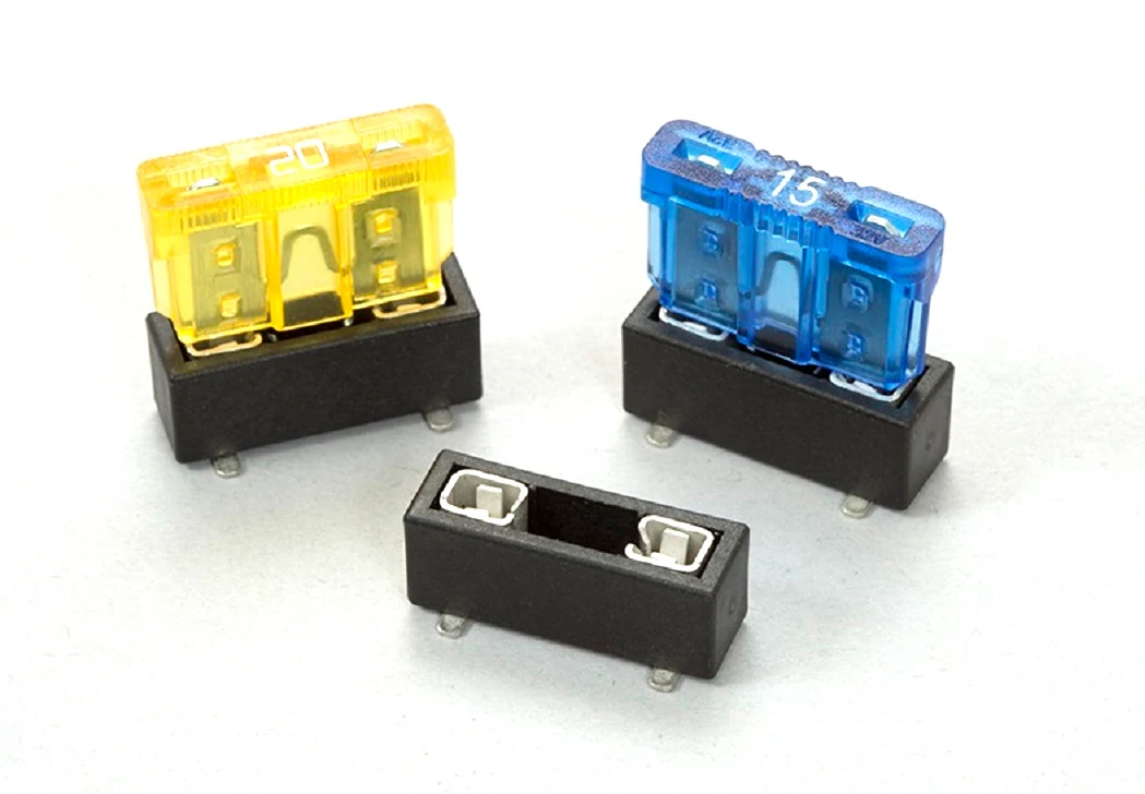
This image displays multiple panel mount fuse holder designs. Panel mount holders are commonly used when fuse replacement needs to be accessible from outside the enclosure. Proper selection requires checking panel cutout dimensions, terminal style, voltage rating, and current capability.
A 5×20 mm marking is a starting point, not a complete mechanical approval.
Most buyers read “5×20 fuse holder” as if it describes one universal part. In practice, the holder still has a defined contact spacing, body height, cap structure, fuse extraction direction, terminal style, and sometimes a cover or carrier that changes the installed envelope. The nominal fuse length and diameter help narrow the search, but they do not remove the need to check the drawing.
This matters more when a project changes from a glass fuse to a ceramic fuse. The outside size may remain similar, but the use case often changes: higher fault energy, less visible element inspection, different replacement expectation, or higher temperature around the protection area. The holder must be checked as part of that new condition.
Treat 5×20 mm as a controlled mechanical interface
The approval drawing should answer a few basic questions before the part is released:
| Check Field | What to Confirm | Common Risk |
| Fuse diameter | Holder accepts the exact fuse body size | Loose or overly tight contact |
| Fuse length | Contact spacing matches the fuse | Poor end-cap engagement |
| End-cap contact area | Clip or carrier touches the correct metal area | High resistance |
| Holder height | Fits under cover or enclosure | Assembly interference |
| Extraction clearance | Fuse can be removed after final assembly | Service failure |
| Terminal style | PCB, solder lug, quick-connect, or wire termination | Wrong production process |
| Cover / cap style | Tool-free, slotted, screw cap, or open clip | Wrong user access level |
A technically correct 5×20 holder can still be wrong if the fuse cannot be removed without bending the clip or lifting the board. That kind of problem is often missed in sample inspection because the holder is tested on an open desk, not inside the final enclosure.
Confirm whether the holder uses direct clips, a carrier, or a cover
A 5×20 design may use open PCB clips, a covered PCB holder, a panel-mounted carrier, or an enclosed cartridge fuse holder. Each one changes the practical behavior.
Open clips save height and part count, but the fuse is exposed. A covered PCB holder adds protection but may reduce access space. A panel carrier makes replacement easier from outside the enclosure, but it adds panel cutout requirements and rear wiring clearance. An enclosed tube fuse holder can protect the fuse better, but it may hide visual inspection and require more installation space.
For procurement, describe the holder structure in the BOM. “5×20 fuse holder” is too thin. “5×20 mm PCB fuse holder, THT, with cover, rated current and voltage per approved drawing” gives the supplier much less room to substitute the wrong part.
Why can a 30A fuse holder overheat below its nameplate rating?
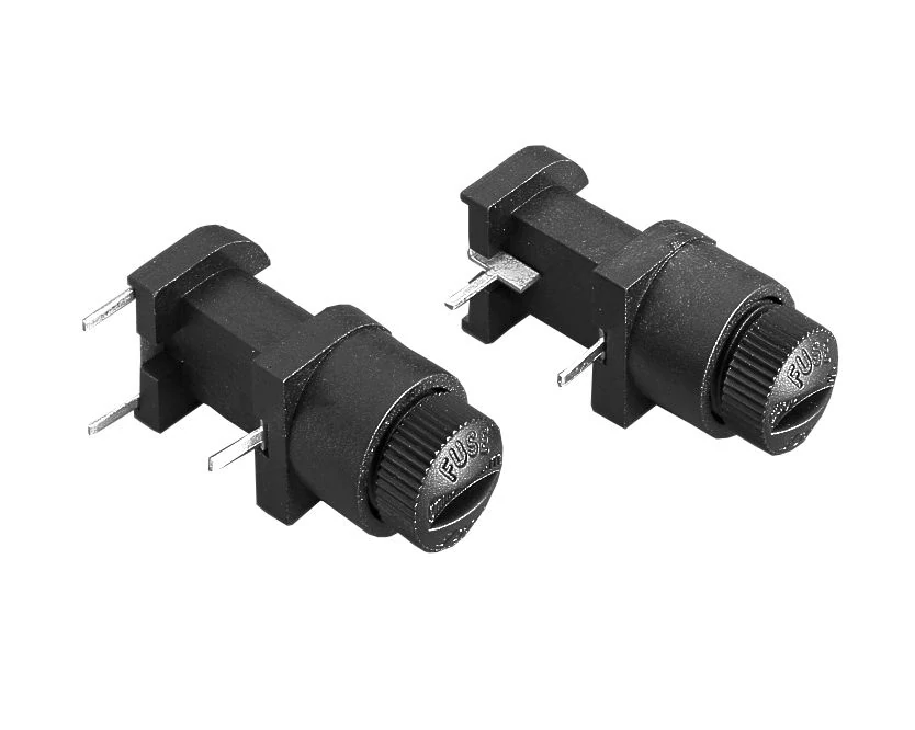
This image shows different fuse holder components including cartridge fuse clips, covers, and mounting parts. Fuse holder performance depends on contact pressure, material quality, mechanical retention, and electrical specifications.
A 30A fuse holder is not automatically a 30A continuous-current solution.
The printed current is only one part of the thermal story. Heat is generated through the fuse, contacts, terminals, solder joints, crimp points, and wiring. If the contact resistance is higher than expected, the holder can heat up even when the fuse does not open.
The fuse responds to current and time according to its own curve. The holder responds to contact resistance, local temperature, material limits, and heat dissipation. Those are different failure paths.
Use approval system and power acceptance, not current alone
A useful current example is SCHURTER’s FIZ 5×20 mm panel fuseholder. The current data lists the holder as 16 A under VDE and 30 A under UL/CSA, with rated power acceptance of 4 W / 16 A at 23°C and higher-temperature derating data to be checked separately
The engineering takeaway is simple:
“30A fuse holder” is not a complete thermal specification.
The buyer still needs to check the exact datasheet, approval system, ambient temperature, rated power acceptance, terminal configuration, wire size, and enclosure condition.
Do not approve a high-current holder only from the catalog title. For 20 A, 25 A, and 30 A circuits, ask for the actual datasheet and define the temperature-rise test condition before production release.
How do voltage rating and insulation limits affect a 250V fuse holder?
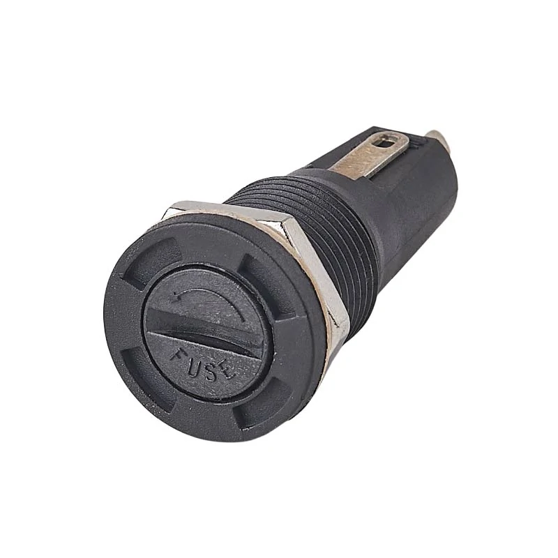
This image shows a 5×20 mm panel mount fuse holder commonly used with cartridge fuses. The holder provides external fuse access while requiring correct matching of fuse size, voltage rating, current rating, and installation environment.
A 250 V fuse does not upgrade a lower-rated holder.
The fuse, holder, wiring, PCB spacing, terminals, and enclosure insulation all have to support the circuit voltage. If one part of that chain is lower-rated or poorly spaced, the assembly should be treated according to the weakest approved point.
That is especially important when a buyer replaces a holder by appearance. Two holders may accept the same fuse and have the same cap shape, but one may be rated for a lower voltage, different approval system, or different mounting environment.
Match AC and DC conditions separately
Do not assume VAC and VDC ratings are interchangeable.
Some holders list AC only. Some list DC separately. Some have different approval values under IEC, UL, CSA, or VDE systems. The exact product specification controls the decision.
A practical screening rule is:
Vsystem ≤ minimum approved voltage rating of fuse, holder, wiring, terminals, PCB layout, and insulation
For user-accessible holders, also check touch protection and cap construction. A panel holder on the outside of equipment has a different safety expectation than an internal PCB holder that only a technician can reach.
When does a fuse clip outperform an enclosed holder?
A fuse clip is useful when the design values low height, low part count, and simple PCB assembly.
It is not automatically a cheaper version of an enclosed holder. It is a different architecture. The exposed fuse, spring contact, end-stop design, board spacing, and surrounding insulation all become part of the safety and reliability review.
Fuse clips often make sense in internal electronics where the fuse is not user-replaced, the enclosure already provides protection, and the board layout has enough clearance. They become risky when the fuse is exposed to handling, dust, vibration, or accidental tool contact.
| Requirement | Fuse Clip | Enclosed Holder |
| Lowest profile | Strong | Weak to medium |
| Visual inspection | Strong | Medium |
| Finger protection | Weak | Stronger |
| Environmental protection | Weak | Depends on design |
| Automated PCB assembly | Strong | Depends on holder style |
| Repeated user replacement | Limited | Stronger |
| Minimum part count | Strong | Medium |
| Contact exposed to handling | Higher risk | Lower risk |
The contact design matters. Clip material, plating, spring force, fuse end-cap size, and replacement cycles all affect long-term resistance. A clip that feels tight during first assembly may relax after repeated fuse changes or lose contact quality after oxidation or vibration.
For low-current internal circuits, a fuse clip can be completely reasonable. For higher current, vibration, user access, or contaminated environments, an enclosed holder or protected PCB holder may be the safer design choice.
The part may still pass continuity. That does not mean the contact system is ready for production.
Design PCB mounting around heat, soldering, and service access
A PCB fuse holder is not just a footprint.
The board becomes part of the holder’s thermal path. Current passes through the fuse, contacts, solder joints, copper pads, and traces before the heat finally spreads into the board and enclosure air. If the copper is too narrow, the nearby components are already hot, or the holder sits under a tight cover, the same fuse holder can behave very differently from the datasheet test condition.
For PCB designs, check three things together: electrical rating, soldering process, and service access. A part that is correct for hand assembly may not survive reflow. A holder that fits the PCB may still be blocked by connectors or wiring after final assembly.
Use this layout check before releasing the board:
| Check Item | What to Confirm |
| Holder footprint | Matches approved drawing |
| Soldering process | THT, SMT, THR, wave, reflow, or hand soldering |
| Copper width | Supports current and heat spreading |
| Nearby heat sources | Transformers, MOSFETs, resistors, heat sinks |
| Fuse removal direction | Not blocked after final assembly |
| Cover clearance | Fuse and holder do not hit enclosure |
| Test-point access | Allows inspection after assembly |
| Service approval | Internal service only or user-accessible |
A common mistake is approving the holder on a bare board. The real test is the assembled product.
Protect panel-mounted holders from rotation, touch, and vibration
Panel holders fail in mechanical ways before they fail electrically.
The cap is opened. The user applies torque. The holder body rotates slightly. Behind the panel, wires twist, solder lugs flex, or quick-connect terminals loosen. After several replacement cycles, the contact path changes enough to create heat or intermittent operation.
For a panel mount fuse holder, the cutout must match the exact drawing. Check panel thickness, nut torque, anti-rotation shape, gasket position, rear terminal clearance, and whether the installed cap gives enough touch protection for the equipment type.
Do not ignore vibration. In equipment shipped by truck, mounted in cabinets, or installed near motors, vibration can affect fuse retention and contact resistance. A holder that looks stable on the bench may loosen after repeated movement.
How should contact resistance be checked before release?
Measure the complete holder path, not one loose metal contact.
Contact resistance can come from the fuse-to-clip interface, clip material, terminal plating, solder joint, crimp joint, or quick-connect terminal. If the test only touches one part of the metal contact, it may miss the real heating point in the installed assembly.
For higher-current designs, add a loaded temperature-rise test. The test should copy the final condition as much as practical: normal current, expected ambient temperature, enclosure state, wire size, PCB copper, and fuse type.
Do not create one universal milliohm limit for every holder. Use the approved datasheet, golden sample, project temperature-rise requirement, and risk level. A low-current internal fuse clip and a 30A panel holder should not be judged with the same shortcut.
Match environmental protection to the real enclosure
An enclosed fuse holder is not automatically waterproof.
Environmental protection depends on the actual design: open clip, covered PCB holder, panel holder with gasket, sealed panel holder, or wire-harness inline holder. Indoor dry electronics may need only basic guarding. Outdoor or vehicle equipment may need sealing, corrosion resistance, and stronger vibration control.
Keep inline sealed applications for the dedicated inline fuse holder article. For this page, the key point is boundary control: if the fuse is in a wire harness, the selection problem changes to wire gauge, crimping, sealing, routing, and strain relief.
For panel and PCB holders, check:
| Environment | Holder Risk | Recommended Action |
| Indoor dry enclosure | Low to medium | Confirm rating and access |
| Dusty cabinet | Medium | Consider cover or enclosed design |
| Condensation | Medium to high | Review sealing and material rating |
| Outdoor moisture | High | Use suitable IP-rated holder |
| Vibration | High | Check retention, terminals, and anti-rotation |
| High ambient temperature | High | Review derating and loaded temperature rise |
Temperature and material rating should be reviewed together. Housing material, flammability rating, terminal plating, contact spring force, and corrosion resistance all affect long-term behavior.
How should incoming fuse-holder lots be screened before production?
Lot inspection should catch obvious substitution before the holder reaches assembly.
Start with identity: holder family, fuse size, mounting method, terminal style, housing, cap, clips, markings, and packaging label. Then sample critical dimensions against the approved drawing. For high-current or safety-critical applications, add contact resistance, retention, and temperature-rise checks by risk level.
A simple lot release matrix keeps the inspection from becoming a vague visual check:
| Characteristic | Method | Sampling | Acceptance | Failure Action |
| Part identity | Visual | 100% label check | Approved BOM | Quarantine |
| Fuse fit | Golden fuse | Sample | Full engagement | Hold |
| Critical dimensions | Gauge / caliper | Sample | Drawing | Hold |
| Contact continuity | Electrical | Defined plan | Pass | Investigate |
| Contact resistance | 4-wire / defined method | Risk-based | Project spec | Expand sample |
| Retention | Mechanical | Risk-based | Project spec | Hold |
| Temperature rise | Loaded test | Qualification / change | Approved limit | Reject or review |
| Documentation | Datasheet / approval | Lot | Required records | Hold |
The dangerous shortcut is still the same: fuse fits plus continuity passes. That is not enough for production release.
If the project is still unsure whether the fuse body itself is correct, go back and verify cartridge size and electrical rating before approving the holder.
FAQ
Can every 5×20 fuse be installed in every 5×20 fuse holder?
No. Matching the nominal 5×20 mm size is only the first check. The holder must also support the current, voltage, thermal load, contact geometry, mounting method, and service environment.
Can a 30A fuse holder safely carry 30A continuously?
Not automatically. Continuous capability depends on the exact holder, approval system, ambient temperature, contact resistance, wiring, enclosure, and manufacturer derating data. Treat “30A fuse holder” as a search term, not as a complete design approval.
Does a 250V fuse require a 250V fuse holder?
The holder must be rated appropriately for the actual circuit voltage and installation. A 250 V marking on the fuse does not upgrade a lower-rated holder, PCB layout, wiring system, or insulation structure.
Why can a fuse holder become hot even when the fuse does not open?
The holder itself generates resistive heat. Contact-path heating follows approximately P = I²R, so loose contacts, oxidation, weak spring force, poor crimping, or insufficient contact pressure can create temperature rise without reaching the fuse opening threshold.
Is an open fuse clip electrically equivalent to an enclosed fuse holder?
Not for the complete installation. Both can connect a fuse to the circuit, but they differ in finger protection, mechanical retention, environmental protection, accessibility, and assembly method.
What should be checked when replacing a damaged fuse holder?
Confirm fuse size, holder current and voltage ratings, mounting dimensions, terminal type, environmental protection, contact condition, thermal capability, and required safety approvals. A mechanically similar holder should not be treated as a direct replacement until those fields are verified.
Final buying guidance
A fuse holder should be specified with the same discipline as the fuse.
For a clean BOM, write the requirement in a way that prevents unsafe substitution:
Fuse holder, for 5×20 mm cartridge fuse, panel mount or PCB mount as specified, rated for circuit voltage and current, with approved terminal type, contact material, operating temperature, safety approval, and replacement access.
For small repair jobs, the same rule applies. Match the installed fuse, the circuit rating, and the mounting structure before ordering a replacement. If the holder shows heat discoloration, loose contacts, cracked housing, or weak retention, do not replace only the fuse and call the repair finished.
A holder is a small part. In the circuit-protection path, it is not a small decision.
