
A cable assembly can pass a continuity test and still be the wrong RF part.
This happens more often than many buyers expect. The connector mates correctly, the cable looks acceptable, and the first sample works on the bench. Problems usually appear later: the cable is installed with a tighter bend radius, the operating frequency moves closer to the upper limit, or the production batch uses a slightly different cable construction.
For RF systems, a coaxial cable assembly is not simply a cable with two connectors attached. The cable type, connector interface, termination method, length, and test requirements together determine whether the assembly will behave correctly in the final application.
This guide explains how engineers and purchasing teams should evaluate coaxial cable assemblies before ordering samples or moving into production.
How Do Coaxial Cable Assemblies Create Reliable RF Connections?
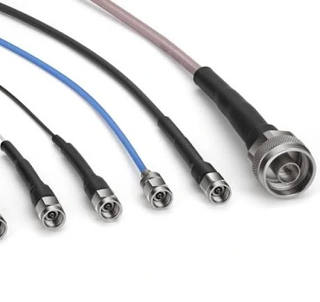
Flexible coaxial cable assemblies with different connector configurations designed for RF modules, wireless equipment, antennas, and electronic systems.
Many RF projects start with a simple requirement: connect one port to another.
The mistake is treating the cable assembly as only a mechanical connection. In low-frequency applications, this approach may work. At higher frequencies, the assembly becomes part of the RF circuit.
A finished coaxial cable assembly normally includes:
- A selected coaxial cable
- Installed RF connectors
- Defined cable length
- Controlled termination process
- Inspection requirements
Compared with purchasing raw coax cable and assembling it internally, a finished assembly reduces several production variables. Connector installation errors, incorrect stripping dimensions, poor solder joints, and inconsistent crimping can all affect RF performance.
For OEM production, this consistency matters because hundreds or thousands of assemblies may need to perform the same way.
For example, an SMA cable assembly used inside a wireless module may require a specific cable diameter, connector style, and routing direction. A connector that physically fits the port may still be unsuitable if the rear cable entry does not match the selected coax.
This is a common sourcing issue:
The front interface looks correct. The assembly behind the interface is wrong.
A practical RF purchase specification should include more than the connector name. The buyer should define:
| Specification Item | Example Requirement |
| Connector A | SMA Male |
| Connector B | U.FL / N Female |
| Cable Type | RG316 / RG174 / Low-loss coax |
| Impedance | 50Ω |
| Length | 300 mm |
| Frequency | DC-6 GHz |
| Termination | Crimp / solder |
| Test Requirement | VSWR / insertion loss if required |
Identify where coaxial cable assemblies are used
Coaxial cable assemblies appear in many RF systems because they provide a ready-to-install connection between components.
Typical applications include:
- RF communication equipment
- Antenna systems
- Wireless modules
- GPS devices
- Industrial electronics
- Laboratory test equipment
- Microwave measurement systems
The required cable assembly changes depending on the environment.
A short internal connection inside an electronic enclosure may prioritize flexibility and small diameter. A connection between an outdoor antenna and communication equipment may require lower attenuation, stronger mechanical construction, and environmental protection.
The same connector family can also have different requirements depending on the cable.
A small SMA assembly using RG316 is common for compact RF modules. A larger cable assembly using low-loss coax may be preferred for longer transmission distances where attenuation becomes the main concern.
Separate coaxial cable assemblies from adapters and connectors
A frequent purchasing mistake is mixing different RF component categories.
A connector, adapter, and cable assembly solve different problems.
| Product | Main Function | Typical Use |
| Connector | Terminates cable or PCB interface | Cable manufacturing |
| Adapter | Converts one interface to another | Equipment connection |
| Cable Assembly | Provides complete RF signal path | Direct installation |
| Custom Assembly | Matches special requirements | OEM production |
A connector alone does not provide a complete connection.
An adapter can solve interface differences, but adding more transitions may introduce additional insertion loss and mechanical points.
A cable assembly combines the cable and connector selection into one controlled component. This is why many equipment manufacturers prefer ordering finished assemblies instead of building them internally.
How Should You Select Connectors for a Coaxial Cable Assembly?
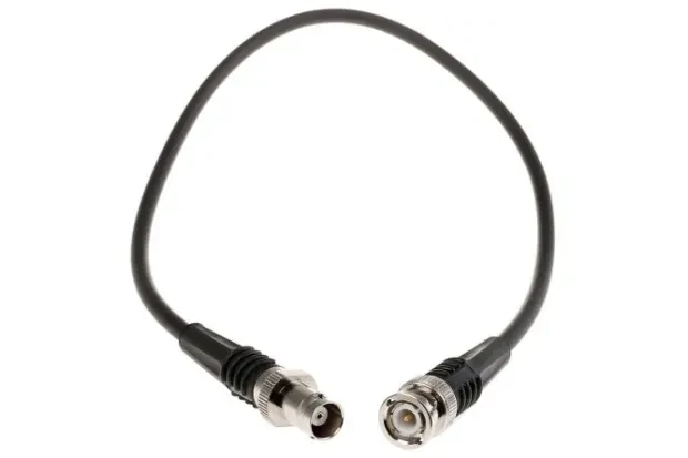
A black coaxial cable assembly featuring RF connectors on both ends, designed for stable signal transmission in RF systems, communication equipment, and electronic applications.
The connector is only one part of the assembly, but a wrong connector choice can affect the entire RF path.
Two connectors may look almost identical in a product image. Their cable compatibility, frequency capability, and internal geometry may be different.
The selection process should start from the equipment interface and application requirement, not from the connector appearance.
Match connector families with equipment interfaces
Common coaxial cable assembly connector options include:
| Connector | Common Application | Typical Cable Match |
| SMA | RF modules, test systems | RG316 / RG174 |
| BNC | Test equipment, video systems | RG58 / RG59 |
| N Type | Antenna and outdoor RF | Low-loss coax |
| TNC | Rugged RF systems | RG58 / RG316 |
| F Type | Broadband/video | RG6 / RG11 |
The connector family determines the mating interface, but the cable determines whether the complete assembly is suitable.
A high-frequency connector cannot automatically improve a cable assembly if the selected coax cable has already become the limiting factor.
For example, a microwave-rated connector installed on a cable with unsuitable attenuation characteristics will not create a high-performance assembly.
Choose connector gender and mounting style correctly
Before production, confirm:
- Male or female interface
- Plug or jack structure
- Bulkhead requirement
- Panel mounting requirement
- Cable entry direction
These details affect both installation and assembly cost.
A bulkhead connector may require a different rear structure compared with a standard cable plug. Right-angle versions may save installation space but can introduce additional mechanical constraints.
For production orders, the connector drawing and cable specification should be reviewed together.
A simple BOM description such as:
“SMA cable”
is usually not enough.
A better specification includes:
“SMA male straight plug, 50Ω, RG316 compatible, 300 mm cable length, DC-6 GHz application, crimp termination.”
This level of detail reduces incorrect substitutions during purchasing.
How Does Coax Cable Selection Affect Assembly Performance?
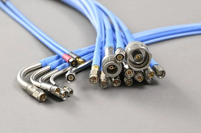
Multiple RF cable assemblies with different coaxial connectors demonstrate customized solutions for communication equipment, antenna systems, and laboratory testing applications.
A connector can be rated for a high frequency range, but the cable assembly may still fail to meet the system requirement.
The cable is often the longest section of the RF path, which means its attenuation, flexibility, shielding, and mechanical behavior directly affect the final result.
A common procurement mistake is selecting the connector first and treating the cable as a secondary item.
For RF assemblies, the cable and connector should be considered as one system.
A practical selection process should evaluate:
- Operating frequency
- Required cable length
- Allowable insertion loss
- Installation space
- Bend radius
- Mechanical stress
- Indoor or outdoor environment
A short cable inside a test fixture and a three-meter antenna cable may use completely different coaxial solutions, even if both systems use the same connector interface.
Compare flexible and low-loss coax options
Different coaxial cable families are designed for different application priorities.
Flexible cables are easier to route inside compact equipment.
For example, RG316 is often suitable for short internal connections because its flexibility makes installation easier. However, replacing a longer low-loss cable with RG316 may create unnecessary signal loss.
A cable that works electrically during a short bench test may not be suitable for the final installation.
Balance cable diameter, flexibility, and attenuation
Cable diameter affects more than mechanical installation.
A larger coax cable generally provides better shielding and lower attenuation, but it requires more space and has a larger minimum bend radius.
A smaller cable is easier to install but may have higher loss.
Engineers should consider the installation environment before selecting the cable.
A cable assembly installed near moving mechanical parts may fail from physical stress before showing any obvious electrical issue.
The connector may remain intact, but the cable transition area can experience repeated force.
For this reason, production cable assemblies often require:
- Strain relief
- Controlled cable routing
- Defined bend radius
- Pull-force inspection
Select high-frequency cables for advanced RF systems
Higher frequency systems require tighter control over the complete RF path.
Microwave cable assemblies used for testing, measurement, and high-frequency modules often require attention to:
- Connector frequency rating
- Cable attenuation at operating frequency
- Phase stability
- Mechanical repeatability
- Assembly tolerance
A common misunderstanding is that the connector frequency rating determines the entire assembly capability.
It does not.
The cable construction, connector interface, termination accuracy, and installation condition all influence RF behavior.
For example, an assembly using a microwave connector may still show unexpected insertion loss if the cable type is not matched to the application.
How Can You Estimate Coaxial Cable Assembly Loss?
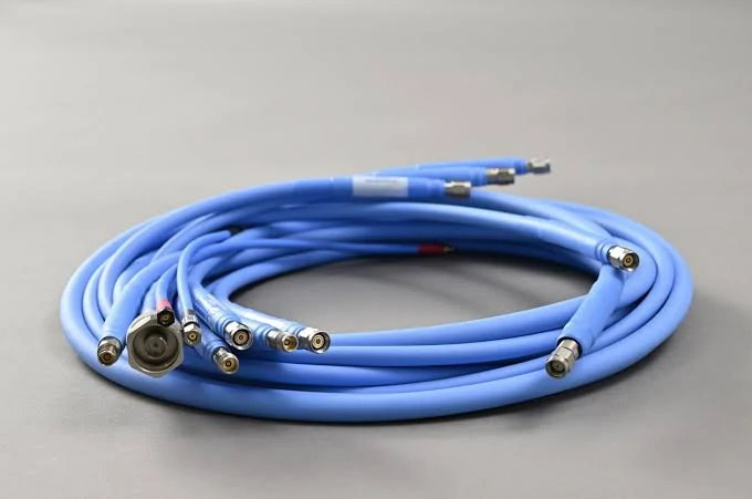
A blue coaxial cable assembly designed for RF applications requiring reliable signal transmission, suitable for antenna systems, wireless devices, and test equipment.
Signal loss is one of the first technical questions buyers should evaluate before selecting a coaxial cable assembly.
The total loss is not only caused by the cable.
The RF path includes:
- Cable attenuation
- Connector transitions
- Adapter connections
- Installation conditions
A short assembly with several adapters may have different loss behavior compared with a longer assembly using direct connectors.
Coaxial Cable Assembly Loss Calculator
| Field | Input |
| Cable Model | RG316 / RG58 / Low-loss coax |
| Frequency | GHz |
| Length | m |
| Cable Loss | dB/m |
| Connector Count | pcs |
| Adapter Count | pcs |
| Total Loss | dB |
This calculation is especially useful during RFQ discussions.
A supplier receiving only:
“Need a 1-meter SMA cable”
still needs more information.
The same SMA cable length can have different results depending on:
- Cable type
- Frequency range
- Connector quality
- Testing requirement
Reserve margin for adapters and installation conditions
Laboratory setups often include multiple transitions:
Equipment port → adapter → cable assembly → adapter → test fixture
Each transition adds another possible mismatch point.
For sensitive RF measurements, reducing unnecessary adapters can improve repeatability.
Installation also matters.
A cable assembly can change performance when:
- Bent beyond specification
- Pulled during installation
- Installed with excessive connector torque
- Routed close to interference sources
A good RF design considers the real installation condition, not only the ideal bench test.
How Are Custom Coaxial Cable Assemblies Manufactured?
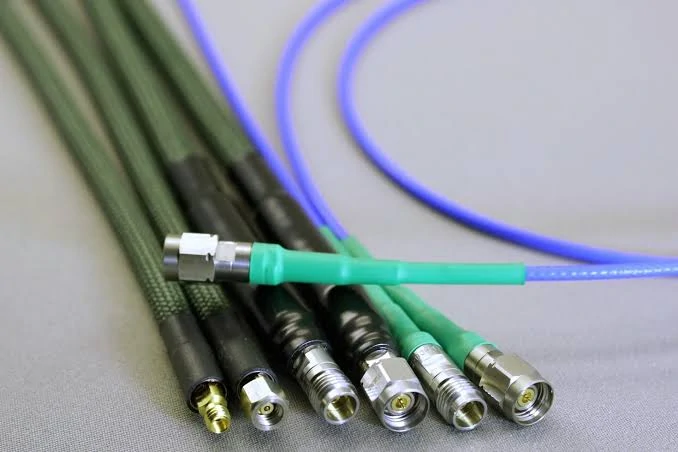
A collection of high-frequency coaxial cable assemblies with precision RF connectors, suitable for microwave systems, laboratory measurement, and communication applications.
Custom assemblies are usually required when standard cable lengths or connector combinations do not match the equipment design.
Typical custom requirements include:
- Special cable length
- Mixed connector interfaces
- Limited installation space
- Specific routing direction
- Additional testing requirements
A custom assembly is not simply a standard cable cut shorter.
The production process affects consistency.
Define cable cutting and preparation requirements
The first production step is preparing the cable correctly.
Important controls include:
- Cutting length accuracy
- Strip dimensions
- Shield exposure
- Center conductor condition
- Cable end preparation
Small dimensional differences can affect connector installation.
For high-frequency assemblies, the relationship between cable geometry and connector structure is important.
How Should You Check a Coaxial Cable Assembly Before It Goes Into Production?
The first sample is usually not the difficult part.
A cable assembly that is manually checked, installed once, and tested on an open bench often looks acceptable. The real challenge appears when the same design moves into production.
A cable route changes.
The operator installs the connector with slightly different force.
The cable supplier provides a material batch with small differences.
None of these issues are obvious from a basic appearance check.
For this reason, production cable assemblies need a clear inspection method before they are released for volume use.
The inspection level depends on the application.
A short internal jumper inside an electronic device may only need basic verification. A microwave test cable used with laboratory equipment requires much tighter control.
Start with mechanical checks before electrical testing
Mechanical inspection is often the first filter.
Before connecting the assembly to equipment, manufacturers usually check:
- Correct connector model
- Cable length
- Connector orientation
- Cable appearance
- Strain relief condition
These checks sound simple, but many production problems start here.
A customer may receive a cable assembly with the correct SMA connector but the wrong cable length.
The RF performance may be acceptable, but the assembly cannot be installed.
Another common issue is connector orientation.
A straight connector and a right-angle connector may use the same interface, but the installation result can be completely different.
For OEM projects, drawings are usually more reliable than product names.
“SMA cable” describes an interface.
It does not describe the complete assembly.
Why does continuity testing not prove RF performance?
Continuity testing is useful, but it answers only one question:
Is the electrical path connected?
It does not answer:
Does the RF signal pass correctly at the operating frequency?
A cable assembly may pass continuity and still have problems caused by:
- Impedance variation
- Poor connector termination
- Damaged dielectric
- Incorrect cable selection
- Excessive bending
This difference becomes more obvious at higher frequencies.
For example, a cable used at a few hundred MHz may tolerate small mechanical variation. The same variation can become measurable in a multi-GHz application.
When the cable assembly is part of a test system, communication link, or microwave module, additional RF measurements may be necessary.
Which RF tests are commonly used for cable assemblies?
The required test depends on what the assembly is expected to do.
| Test | Purpose | Common Application |
| Continuity | Check electrical connection | General production |
| VSWR | Check impedance matching | RF systems, antennas |
| Insertion Loss | Measure signal attenuation | Test cables, communication links |
| Return Loss | Evaluate reflected signal | Microwave applications |
Not every assembly needs a full VNA report.
Adding unnecessary testing increases cost and production time.
The better approach is matching the inspection requirement to the actual application.
A short cable inside a finished product and a precision laboratory cable should not share the same acceptance standard.
When Does a Standard Coaxial Cable Assembly Become the Wrong Choice?
Many buyers start with standard products because they are faster to purchase.
That is reasonable.
If the connector combination, cable type, and length already match the equipment, a standard assembly can save development time.
The problem starts when the standard product is modified repeatedly.
A cable becomes:
- Slightly longer
- Changed to another connector
- Bent into a different routing path
- Used outside the original frequency range
At this point, the product may no longer be a standard assembly.
Use standard assemblies when the application is already defined
Standard coaxial cable assemblies work well for common RF connections.
Typical examples:
- Laboratory connections
- Prototype testing
- Equipment maintenance
- Internal module connections
The advantage is availability.
However, buyers should still check the actual specification.
A catalog description such as:
“SMA to SMA cable”
does not tell the whole story.
The assembly may differ in:
- Cable diameter
- Cable material
- Frequency capability
- Connector termination
- Shielding structure
Two products with the same connector combination may perform differently.
Consider custom assemblies when installation creates constraints
Custom cable assemblies are usually driven by the equipment design.
For example:
A wireless module may require a very short cable because there is limited space inside the enclosure.
A test fixture may need a specific connector position because the cable cannot interfere with measurement access.
An antenna system may require a longer low-loss cable because attenuation becomes the limiting factor.
In these cases, customization is not about making the product more complicated.
It is about making the RF path match the equipment.
What Details Should Be Prepared Before Requesting a Coaxial Cable Assembly Quote?
Incomplete RF requests are common.
A supplier may receive a message like:
“Please quote SMA cable, 500 pcs.”
The problem is not the quantity.
The problem is that the technical information is missing.
The supplier still needs to determine:
- Which SMA interface?
- What cable?
- What length?
- What frequency?
- What termination?
- What application?
A few minutes spent preparing the RFQ can prevent multiple quotation revisions.
Describe both ends of the assembly
The connection path should be clear.
Example:
Incorrect:
SMA cable 300 pcs
Better:
SMA male to N female cable assembly, RG316 cable, 500 mm length, 50Ω, used for RF test equipment.
The second description immediately gives the supplier a workable starting point.
Specify the cable based on application, not habit
Different applications have different priorities.
A buyer working on a GPS device may care more about:
- Compact size
- Flexibility
- Routing space
A buyer working on an antenna system may care more about:
- Lower attenuation
- Outdoor durability
- Longer service life
The cable choice should follow the application.
Not every RF project needs the lowest-loss cable.
Not every compact device can accept a large coax cable.
Coaxial Cable Assembly RFQ Information Sheet
Before sending a request, prepare the following information:
| Item | Example |
| Connector Side A | SMA Male |
| Connector Side B | N Female |
| Cable Model | RG316 |
| Length | 500 mm |
| Impedance | 50Ω |
| Frequency Range | DC-6 GHz |
| Application | RF Test / Antenna |
| Quantity | Sample / Production |
| Drawing | If custom |
| Test Requirement | VSWR / Loss |
FAQ
Why does my cable assembly work at low frequency but fail at higher frequency?
Higher-frequency signals are more sensitive to impedance changes and manufacturing variation. A small difference in connector termination or cable structure may have little effect at low frequency but become measurable in GHz applications.
Can I replace one coaxial cable assembly with another using the same connector?
Not always.
The connector interface may be identical, but the cable type, frequency capability, impedance, and mechanical structure may be different. The complete assembly specification needs to be checked.
Why does a coaxial cable assembly fail after installation even though the sample worked?
A common reason is that the final installation condition is different from the original sample test. The cable may be bent tighter, routed differently, or used closer to the upper frequency limit. A short bench test cannot always represent the production environment. Before mass ordering, it is better to confirm the cable type, connector combination, installation space, and required RF test conditions.
Is the connector the most important part when selecting a coaxial cable assembly?
Not always. The connector defines how the assembly connects to the equipment, but the cable section often determines the overall loss, flexibility, and mechanical behavior. A high-frequency connector cannot compensate for unsuitable coaxial cable selection. The connector, cable, termination method, and operating frequency need to be evaluated as one complete RF path.
How much information should I provide before ordering a custom coaxial cable assembly?
A supplier normally needs more than just the connector names and quantity. The useful details include both connector ends, cable model, length, impedance, operating frequency, installation environment, and required testing. If the assembly has a special routing direction or limited installation space, providing a drawing early can prevent unnecessary redesign during production.
