
A cable can pass continuity and still fail the RF job.
That is where many connector mistakes start. The center conductor touches. The shield is connected. The nut tightens. On a simple meter, nothing looks wrong. But once the assembly is used in an antenna feed, RF test bench, video path, or production device, the problem appears as unstable signal level, poor return loss, noise, image degradation, or an unexpected mismatch near the operating band.
A coaxial cable connector is not just a metal end fitted onto a cable. It completes the controlled RF path from the cable into equipment, a PCB, an adapter, or another cable assembly. The front interface must mate correctly, but the rear termination must also match the cable diameter, dielectric, braid structure, impedance, and installation method. A connector made for RG316 should not be treated as interchangeable with one made for RG58 just because both may use the same SMA front interface.
For buyers, this is also a sourcing problem. A product title may say “SMA connector,” “BNC connector,” or “coax cable connector,” but that does not confirm impedance, cable fit, frequency range, termination method, or inspection requirement. Those details belong in the RFQ, not in a guess after samples arrive.
How Does a Coaxial Cable Connector Complete the Signal Path?
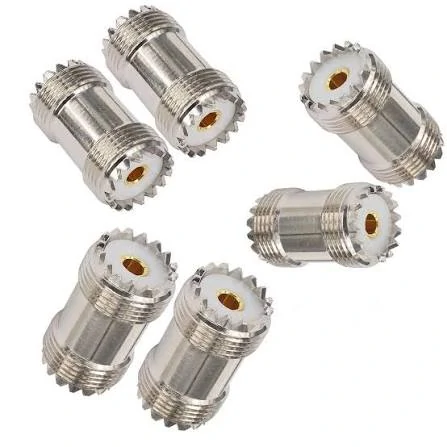
Panel mount bulkhead coaxial cable connector designed for secure installation through equipment enclosures. Suitable for RF devices, test systems, antennas, and custom cable assemblies.
A coaxial cable has a simple-looking structure: center conductor, dielectric, shield, and jacket. The connector has to continue that structure without creating a weak transition point. The center contact carries the signal path. The dielectric supports the center contact and helps maintain geometry. The connector body and shield contact complete the outer conductor path.
That geometry matters more as frequency rises. A slightly loose center pin, damaged dielectric, poor braid contact, or wrong ferrule size may not break continuity. It can still disturb impedance enough to create reflection. At low frequency, the effect may be small. At several GHz, the same mistake becomes easier to measure.
This is why RF connector selection should begin with the cable and application, not only the connector name. A coaxial cable connector for a short RG316 jumper inside a compact RF module has different sourcing risks than a connector for RG213 on an outdoor antenna run. A BNC connector for CCTV is not specified the same way as a BNC connector for a 50Ω test bench. An F Type connector for broadband belongs in a 75Ω system, not a random RF replacement box.
The front interface answers only one question: what does it mate with?
The rear side answers the questions that often cause production trouble:
- What cable series is being terminated?
- What is the actual cable OD?
- Is the inner conductor solid or stranded?
- Is the shield single braid, double braid, or foil plus braid?
- Is the connector crimp, solder, clamp, or compression type?
- Is the system 50Ω or 75Ω?
- Will the assembly be tested for continuity only, or also VSWR and insertion loss?
For a supplier, these details decide the connector body, pin, ferrule, crimp die, solder process, and inspection method. For a buyer, they decide whether the ordered part can be repeated in production.
A common trap is ordering by photo. The connector looks right from the front, but the cable entry is wrong. The operator can sometimes force the cable into the connector, especially on small flexible coax. That does not make it correct. The braid may not sit evenly under the ferrule. The dielectric may be cut too short. The center conductor may not enter the pin consistently. The first sample may work, then production rejects appear later.
If you are comparing cable choices before selecting the connector, TEJTE’s RG cable guide can be used as a supporting reference for cable family, application, and assembly planning: RG cable guide.
Connector Fit Is Mechanical, Electrical, and Process-Related
Mechanical fit is the part buyers see first. The connector must mate with the equipment port, panel jack, adapter, PCB connector, or cable assembly. Gender, thread, bayonet, polarity, nut size, and panel mounting features must be correct.
Electrical fit is less visible. The connector impedance must match the system. Most RF communication and test systems use 50Ω. Video, CATV, and broadband paths often use 75Ω. Some connector families, such as BNC, exist in both impedance versions, so the family name alone is not enough.
Process fit is the part that shows up in manufacturing. A connector that is technically correct but difficult to terminate consistently can still create quality problems. Small cables such as RG178, RG316, or 1.13 mm coax need clean stripping and controlled crimping or soldering. Larger low-loss cables need proper cable prep, shield handling, and strain relief. If the shop floor does not have the correct tooling, the connector choice becomes unstable.
For production cable assemblies, specify the inspection level early. Continuity testing confirms basic electrical connection. It does not prove RF performance. For sensitive assemblies, add VSWR, insertion loss, or VNA sweep requirements at the operating frequency range.
How Do You Match Connector Families to Coax Cable Applications?
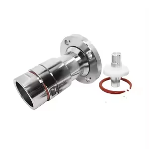
N type RF coaxial connector adapter used for antenna connections, wireless communication systems, and RF equipment. Provides reliable mechanical connection and stable signal transmission.
Start with the equipment interface and the system use. Then narrow the connector by impedance, frequency, cable type, mounting style, and environment.
SMA connectors are common on compact RF modules, antennas, Wi-Fi devices, GNSS equipment, small test jumpers, and lab fixtures. They are useful when space is limited and the system is usually 50Ω. But not all SMA connectors are the same. A straight SMA plug for RG58/RG142 uses a different rear structure from an SMA plug for RG316 or semi-rigid cable. The front thread may look identical. The cable side is not.
N Type connectors are larger and often chosen for antenna systems, outdoor RF equipment, base station accessories, and higher-power RF paths. They are more rugged than small connector families and are available for larger coaxial cables. Cable size, sealing, power level, and installation environment matter here. A connector used outdoors may also need waterproofing, heat shrink, boot protection, or panel sealing.
TNC connectors use threaded coupling and are useful where vibration or mechanical security is more important than quick bayonet connection. They appear in RF communication equipment, antenna feeds, and ruggedized systems. If a cable assembly may move, vibrate, or sit inside equipment with repeated handling, thread security can be a practical advantage.
F Type connectors are usually linked to 75Ω TV, CATV, satellite, and broadband cable systems. They commonly match RG6, RG59, or RG11 style cables. They should not be treated as a general RF substitute just because they are familiar and inexpensive.
PL259 and SO239 connectors still appear in radio and UHF-related equipment. They are mechanically common in some markets, but frequency range, impedance behavior, and application expectations should be checked before using them in a modern RF assembly.
The table below is a practical first-pass filter. It does not replace a datasheet or drawing, but it helps prevent the wrong family from entering the BOM.
| Connector Family | Common Cable Match | Typical Application | Main Check Before Ordering |
| SMA | RG316 / RG174 / RG178 / semi-rigid | RF modules, antennas, test jumpers | Gender, frequency, cable OD |
| BNC | RG58 / RG59 / RG179 | Test equipment, video, CCTV | 50Ω or 75Ω version |
| N Type | RG58 / RG213 / LMR cable | Antenna and outdoor RF systems | Cable size, sealing, power |
| TNC | RG58 / RG316 | Rugged RF links, vibration areas | Thread fit, cable retention |
| F Type | RG6 / RG59 / RG11 | TV, CATV, broadband | 75Ω system compatibility |
| PL259 / SO239 | Larger coax cables | Radio and UHF equipment | Frequency and impedance fit |
This matrix is useful for early selection, but the final specification should be more exact. A buyer should not write only “SMA connector” in the order. A clearer BOM line would say something like:
SMA male plug, 50Ω, straight cable type, for RG316 cable, gold-plated contact, PTFE insulator, crimp/solder termination, target frequency up to the required operating band, continuity test required, VSWR test if used near upper RF range.
That wording gives the supplier something real to build and inspect.
Application Fit Should Override Catalog Convenience
Catalog categories are not always how engineers think. A connector may appear under “RF connectors,” “coax connectors,” “antenna connectors,” or “coaxial cable connector,” but the application decides whether it is a good fit.
For a compact IoT antenna jumper, the key risks are small cable handling, connector retention, bend radius, and repeatable assembly length. For a bench test cable, the buyer may care more about mating cycles, VSWR repeatability, and connector wear. For a CCTV or broadband run, 75Ω compatibility and cable installation quality may matter more than GHz rating. For an outdoor antenna feed, waterproofing and cable loss may become more important than the connector family alone.
There is also a difference between buying loose connectors and buying finished coaxial cable assemblies. Loose connectors make sense when the customer has tooling and process control. Finished assemblies are safer when cable length, stripping, crimping, soldering, labeling, and RF testing need to be repeated across batches.
If the assembly will be installed inside an enclosure, leave space for the bend radius and tightening tool. Many failures are not caused by the connector selected on paper. They come from forcing a cable into a tight corner after the connector has already been terminated.
How Should 50Ω and 75Ω Systems Be Separated?
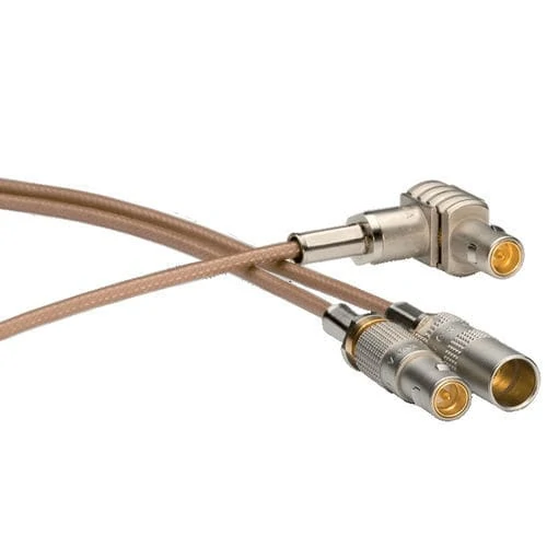
High-quality coaxial cable connector assembly featuring SMA and BNC RF connectors. Designed for reliable signal transmission in RF testing, communication equipment, antennas, and electronic systems.
Do not use connector shape as the final selection rule.
This mistake appears often with BNC, F Type, and older coax replacement parts. A connector may fit the port, lock in place, and pass a simple signal check. That does not prove the impedance is correct. In RF test systems, antenna feeds, video links, or broadband paths, a wrong impedance choice can show up later as return loss, level variation, noisy images, or a cable assembly that cannot repeat the same result across batches.
Most RF communication, antenna, and lab systems are built around 50Ω. Many video, CATV, and broadband systems are built around 75Ω. The difficult part is that some connector families are available in both versions. BNC is the common example. A buyer may see “BNC connector” in a catalog and assume the rest is obvious. It is not.
For purchasing, always write the impedance into the RFQ or BOM. “BNC male for RG59” is still incomplete if the application is not clear. “BNC male, 75Ω, for RG59, video cable assembly” gives the supplier a much safer direction.
| System Requirement | Usual Impedance | Common Connector Direction | Risk if Mixed |
| RF module or wireless device | 50Ω | SMA / MMCX / U.FL | Reflection or unstable signal |
| RF test bench | 50Ω | SMA / BNC / N Type | Measurement error |
| Antenna system | Usually 50Ω | N Type / TNC / SMA | Mismatch and extra loss |
| CCTV or video | 75Ω | BNC / F Type | Image degradation |
| CATV or broadband | 75Ω | F Type | Return path issues |
| Unknown replacement part | Confirm first | Do not guess | Wrong purchase |
If the customer only has a photo of the old connector, ask for the cable marking, equipment type, and application. When there is no marking, a sample or drawing is better than guessing. A visually similar coaxial cable connector can still be the wrong electrical part.
How Do Cable Diameter and RG Series Affect Connector Choice?
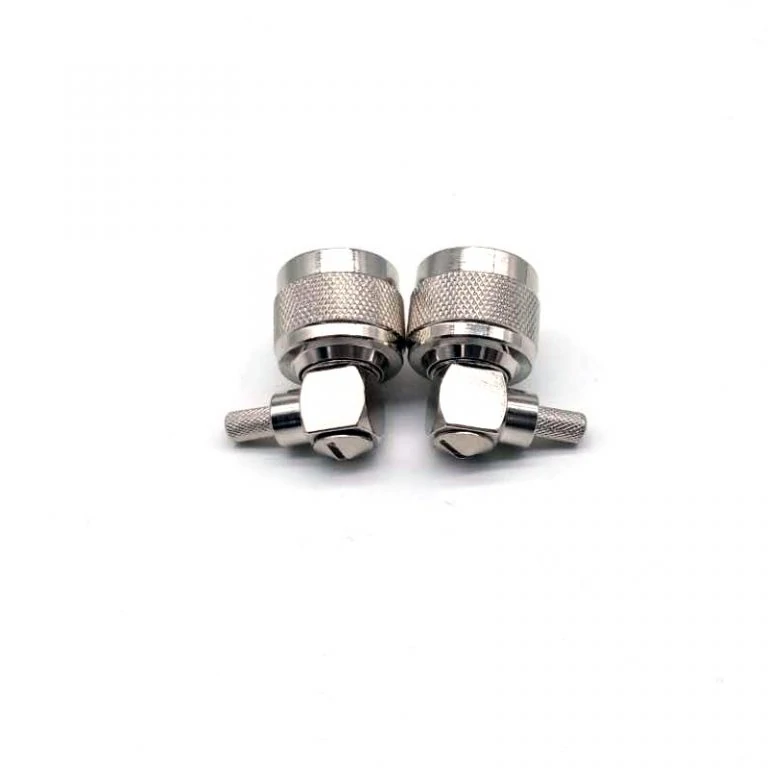
Right angle coaxial cable connector designed for RF equipment, cable assemblies, and compact electronic applications. The angled structure improves cable routing flexibility while maintaining reliable RF connection.
The cable side of the connector causes many hidden failures.
RG316, RG174, RG178, RG58, RG59, RG6, RG213, and LMR-style cables do not share the same outer diameter, dielectric size, shield structure, or inner conductor design. A connector made for one cable group should not be treated as universal. Sometimes the cable can be forced into the rear body. That is worse than an obvious no-fit because the defect may not appear until bending, pull testing, or RF testing.
Small flexible coax is common in compact RF modules, antennas, IoT devices, and internal jumpers. It needs clean stripping and controlled crimping or soldering. The braid can be damaged easily. The dielectric can deform if the process is rough. Larger coaxial cables are often used for lower loss, longer antenna runs, or outdoor equipment. They need the correct ferrule, clamp structure, strain relief, and sometimes sealing.
A good cable-to-connector check should include these fields before samples are ordered.
| Check Field | Required Detail |
| Cable Series | RG316 / RG58 / RG6 / RG213 / LMR / custom |
| Cable OD | Actual mm or inch value |
| Inner Conductor | Solid or stranded |
| Dielectric Size | Must match connector design |
| Shield Type | Braid, foil, or double shield |
| Termination Method | Crimp, solder, clamp, or compression |
| Ferrule Size | Matched to cable OD |
| Drawing or Sample | Needed for replacement or OEM work |
This is not extra paperwork. It prevents wrong substitutions. A supplier may stock several SMA male plugs with similar front interfaces. One may fit RG316. Another may fit RG58 or RG142. Another may be for semi-rigid cable. The front thread looks familiar, but the rear structure decides whether the cable can be terminated correctly.
Crimp termination is efficient in production, but only with the correct ferrule and die. A loose crimp can reduce shield contact. An over-crimp can deform the dielectric. Solder termination may work well for small batches or specific pin designs, but excess heat can shift the center conductor or damage insulation. Clamp and compression connectors are useful for some larger coax cables, but they still depend on proper cable preparation.
Continuity testing alone is not enough for sensitive RF assemblies. It confirms the connection is not open or shorted. It does not confirm VSWR, insertion loss, or impedance behavior at the working frequency.
How Do Mounting Styles Change Coaxial Cable Connector Selection?
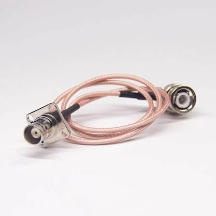
BNC coaxial cable connector assembly providing secure bayonet coupling for RF and signal transmission applications. Suitable for test equipment, communication devices, and electronic measurement systems.
A cable-end connector, a bulkhead connector, a panel connector, and a PCB connector solve different problems.
Cable-end connectors are used on jumpers, antenna leads, test cables, and equipment harnesses. The main checks are cable compatibility, straight or right-angle body, strain relief, and bend space behind the connector. A cable that bends sharply right after the connector can fail even when the connector itself was correctly selected.
Bulkhead connectors pass through a panel or enclosure wall. The thread length, nut size, washer arrangement, and panel thickness must be checked before ordering. A bulkhead SMA jack may look right, but if the panel is too thick or the nut side has no tool clearance, installation becomes unstable.
Panel-mount connectors are fixed equipment ports. They may use a flange, threaded body, solder cup, PCB pin, or rear coax termination. For these parts, the drawing matters. Hole position, cutout size, orientation, and rear-side clearance should be defined before mass production.
PCB connectors add another layer of risk because the RF path starts on the board. Footprint, ground layout, launch geometry, and connector height all matter. A good connector cannot fix a poor RF launch.
How Do Coaxial Cable Connectors Work With Adapters and Assemblies?
Adapters are useful, but they should not become the whole RF path.
A coax adapter is a practical choice when equipment ports already exist and the connection is temporary. Lab testing, troubleshooting, and interface conversion often need adapters. The problem starts when two or three adapters are stacked in a permanent product. Each extra interface adds mechanical length, handling risk, and possible RF penalty.
For production, a direct cable assembly is often cleaner. The connector pair, cable length, orientation, label, and inspection requirement can be controlled as one part number. That reduces receiving confusion and makes repeat orders easier.
Use this decision table before approving an adapter stack.
| Question | Choose Adapter | Choose Cable Assembly |
| Temporary test setup? | Yes | Maybe |
| Permanent installation? | Maybe | Yes |
| Multiple adapters needed? | No | Yes |
| Loss or VSWR sensitive? | Maybe | Yes |
| Fixed cable length required? | No | Yes |
| Repeat production needed? | No | Yes |
A clearer RFQ would say: SMA male to N female cable assembly, 50Ω, RG316 or RG58 cable, 300 mm length, straight connectors, continuity test required, VSWR test if used near the upper band.
That is much safer than buying loose connectors and adapters first, then discovering the finished path is too long, too fragile, or inconsistent in testing.
How Should Frequency Range Influence Connector Selection?
Frequency rating should be checked before the connector enters the BOM.
A coaxial cable connector that works well at low frequency may not behave the same way near several GHz. The problem is not only the connector name. It is the whole transition: center contact shape, dielectric support, plating, body geometry, cable match, assembly process, and test condition. A connector family may have several versions with different practical limits.
SMA is a good example. A small SMA connector is common in RF modules and test jumpers, but the exact part still matters. A basic SMA cable connector used for a short antenna lead is not the same sourcing decision as a precision microwave connector used in a VNA setup. The cable can also become the bottleneck before the connector rating. A connector may be rated high enough, while the selected coax cable has too much loss at the target band.
Do not select by GHz number alone. A higher rated connector does not automatically make the assembly lower loss. If the cable is long, poorly terminated, sharply bent, or routed through several adapters, the assembly can still test poorly.
For general sourcing, leave margin. If the device works at 5.8 GHz, a connector with no clear high-frequency information is not a safe choice. For sensitive measurement, production RF testing, or microwave equipment, ask for the rated frequency, impedance, VSWR target, cable type, and whether the assembly can be swept.
How Can You Reduce Loss at the Connector-to-Cable Transition?
Loss does not come from one place.
Cable attenuation, connector transition, adapter count, bend radius, and termination quality all add up. The connector-to-cable transition is small, so buyers sometimes ignore it. That is a mistake on short test jumpers and compact RF assemblies, where every interface is close to the active device.
Use the formula as a planning tool, not a final test result. Exact values still depend on frequency, connector quality, cable construction, and measurement method.
| Field | Input Needed |
| Cable Type | RG316 / RG58 / RG6 / low-loss coax |
| Frequency | MHz or GHz |
| Cable Length | m or ft |
| Connector Count | pcs |
| Adapter Count | pcs |
| Estimated Cable Loss | dB |
| Estimated Connector Loss | dB |
| Total Estimated Loss | dB |
This is the original information asset for the article. It helps buyers see why a “small adapter” is not always small in RF terms. One adapter in a temporary test setup is normal. Three adapters in a production cable path should trigger a redesign discussion.
The easiest way to reduce risk is boring: use the right connector for the cable, keep stripping consistent, avoid unnecessary adapters, protect the bend behind the connector, and test the assembly at the frequency that matters.
How Should Coaxial Cable Connectors Be Inspected Before Use?
Visual inspection cannot confirm high-frequency behavior, but it can catch many bad parts before they reach the bench.
Check the center contact first. It should not be bent, recessed, loose, or off-center. Threads should be clean. Bayonet slots should not be damaged. The insulator should not show cracks, burns, or deformation. Plating should be even enough for the intended use, especially on parts with repeated mating.
On cable assemblies, inspect the crimp or solder area. The rear body should hold the cable firmly. Heat-shrink should support the transition without forcing a sharp bend. Labels should match the order, especially when similar assemblies use different cable types or connector genders.
| Inspection Item | Acceptance Requirement |
| Connector Family | Matches order |
| Gender / Polarity | Confirmed before mating |
| Impedance | 50Ω or 75Ω confirmed |
| Cable Compatibility | Matches cable OD and structure |
| Center Contact | Not bent, loose, or recessed |
| Thread / Bayonet | No visible damage |
| Crimp / Solder Area | Firm and clean |
| RF Test | VSWR or insertion loss if required |
| Packaging | Protects contacts and threads |
Continuity testing is still useful. It catches opens, shorts, and basic wiring errors. But do not let it become the only quality gate for an RF assembly used near its upper frequency range. If return loss or insertion loss matters, add the test requirement before ordering.
How Do You Specify Coaxial Cable Connectors for Purchasing?
A useful RFQ is specific enough that another buyer can reorder the same part six months later.
Do not write only “coax connector” or “SMA cable.” That creates room for the wrong cable, wrong gender, wrong impedance, wrong rear body, or wrong test standard. A better purchasing note includes interface, gender, impedance, cable model, mounting style, termination method, frequency range, quantity, and inspection target.
For replacement parts, attach photos from multiple angles. If the connector passes through a panel, include panel thickness and hole size. If the cable assembly is used inside equipment, include cable routing and bend space. If the part must match an old batch, send the old drawing, label, or sample.
FAQ
How do I know which connector fits my coaxial cable?
Check the cable series, outer diameter, inner conductor, dielectric size, shield type, impedance, and termination method. The connector must be made for that cable structure. A similar front interface does not prove the rear body or ferrule is correct.
Is a coaxial cable connector the same as an RF connector?
Not always. Many coaxial connectors are used in RF systems, but some are mainly used for video, CATV, broadband, or other coaxial signal paths. Application and impedance decide the correct specification.
Can I use a 50Ω connector on a 75Ω coax cable?
It is not a clean production choice unless the system has been evaluated. Mechanical fit does not guarantee impedance matching. For test systems, broadband, video, and customer equipment, specify the correct impedance.
How do I select a coaxial cable connector for my cable?
Choosing a coaxial connector usually starts from the cable, not from the connector shape.
Two connectors may look almost identical from the outside, but the cable side can be completely different. The contact pin size, ferrule, and rear body design need to match the cable construction.
Can one SMA connector fit different coaxial cables?
Not every SMA connector can be used with every coaxial cable.
The SMA interface on the equipment side may be the same, but the cable termination section is designed for a specific cable size. RG316, RG174, RG178, and RG58 cables require different connector structures.
In production, forcing an unmatched cable into a connector may create hidden problems. The assembly may work at first but become unreliable after bending, pulling, or repeated use.
