
A coaxial cable assembly can pass continuity, look clean under visual inspection, and still fail after installation.
The weak point is usually the short transition behind the connector, where a rigid metal body meets a flexible cable. An installer pulls the cable while tightening an SMA connector. A long RG58 run hangs from a PCB-mounted port. A clamp is placed directly against a stiff boot and creates a new hinge point. The first bench test may show normal continuity and acceptable VSWR, but later the assembly develops unstable S11, jacket wear, connector rotation, or intermittent contact.
A practical coax cable strain relief design must do more than cover the rear of the connector with heat shrink. It must identify where axial pull, side load, torsion, vibration, cable weight, and installation stress enter the RF path. Those loads then need to be transferred into a boot, clamp, bracket, bulkhead, or enclosure before they reach the crimp, solder joint, center conductor, or mated port.
The useful purchasing question is not simply, “Does the cable include strain relief?” It is: “Which load is being controlled, where is it transferred, and how will the finished assembly be verified?”
Where Does Mechanical Load Enter the RF Path?
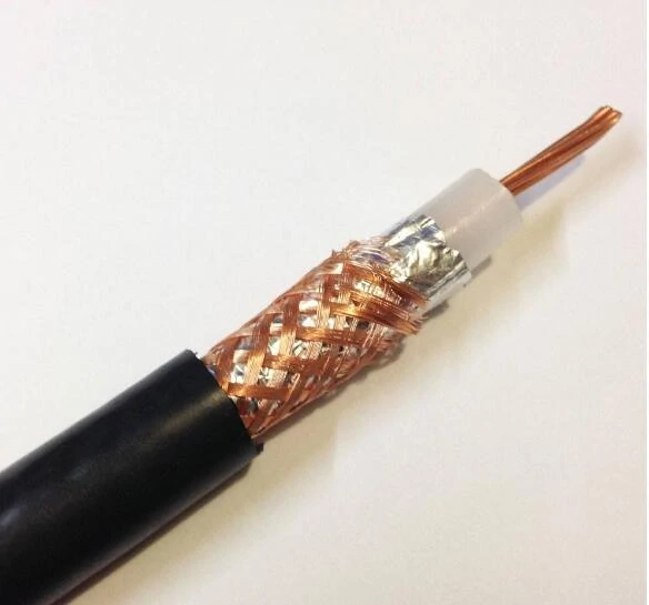
Cross-sectional view of coax cable construction. Understanding internal layers helps evaluate mechanical stress, strain relief performance, and RF reliability.
The connector is often blamed because that is where damage becomes visible. The original load may have entered much farther down the cable.
A vertical run creates a bending moment at the port. A tightly tied harness can keep pulling sideways after installation. A technician can store torsion in the assembly by rotating the entire cable during mating. Even a light RG316 pigtail can damage a small PCB connector if the first bend begins immediately behind the ferrule.
Trace the load through the complete assembly:
Cable Jacket→ Shield or Braid→ Ferrule or Crimp Sleeve→ Connector Body→ Mated RF Port→ PCB or Panel The objective is to interrupt this path before normal service loads reach the electrical termination.
Trace axial pull into the termination
Axial load acts along the cable length. It can come from installation pulling, accidental handling, equipment movement, or a cable bundle tied too tightly farther down the route.
The jacket may appear to carry the force, but it eventually reaches the attachment system. Depending on the construction, that system may include a crimped ferrule, soldered braid, clamped rear body, molded transition, or adhesive-lined sleeve.
A neat sleeve does not prove adequate pull retention. Heat shrink may reinforce the jacket while the force still reaches a weak braid termination underneath it. For sourcing, ask where the axial load is transferred. “Black heat shrink included” is not a mechanical requirement.
Separate side loading from axial loading
Side loading is easier to miss because the cable is not pulled directly away from the connector. Its weight acts at an angle and turns the unsupported length into a lever.
This is common when RG58 is attached directly to a small SMA port, a cable leaves an enclosure without nearby support, an adjacent harness pulls it sideways, or a cover pushes the cable downward after assembly.
Small SMA, MCX, and MMCX interfaces deserve particular attention. The connector may remain mated while the PCB solder joint or cable termination absorbs the bending force. Reducing the unsupported span often does more than adding a thicker sleeve.
Stop torsion before it reaches the crimp
A threaded connector should not be installed by rotating the entire cable.
When the cable becomes the tightening handle, torsion passes through the jacket and shield into the termination. A molded boot may hide the movement without preventing the braid or center conductor from twisting internally.
Check that the coupling nut rotates independently, the connector body can be held where required, the cable reaches the port without stored twist, and the first clamp does not force rotation between two fixed points.
A cable that must be twisted into position needs rerouting, not stronger heat shrink.
Classify the movement correctly
“Flexible cable” is not a complete movement specification. A cable can be flexible enough for one-time installation but unsuitable for repeated cycling at the same point.
| Movement Class | Typical Situation | Main Risk |
| Fixed | Internal enclosure wiring | Cable weight and installation stress |
| Occasional | Maintenance access | Service-loop tension |
| Repeated handling | Bench lead or portable device | Connector-exit fatigue |
| Continuous flexing | Automated motion | Dynamic cable failure |
| Vibration | Vehicle or industrial machine | Support-point fatigue |
| Repeated mating | External antenna or test port | Port loading and cable twist |
A fixed pigtail may need only a boot and nearby support. A handheld lead needs a defined flex zone. Continuous motion may require a dynamic-rated cable and guide system rather than a standard RF jumper with a longer sleeve.
Connector Load-Path Audit
Record the connector, cable type, finished OD, unsupported length, primary load direction, first-bend location, movement class, current support method, abrasion points, and expected failure mode.
The audit should answer one blunt question: Is the RF port carrying cable weight that should be carried by the enclosure?
Which Strain-Relief Method Matches the Failure Mode?
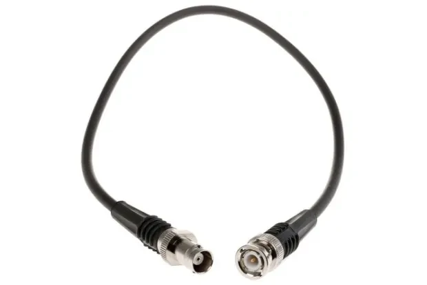
Example of a coaxial cable assembly with connector interfaces. Proper strain relief helps prevent cable bending stress, connector damage, and intermittent RF performance issues.
A boot, clamp, heat-shrink sleeve, spring guard, and bulkhead do different jobs. They may be used together, but they are not interchangeable.
Use a flexible boot to spread local bending
A boot is useful when movement concentrates where the cable exits the connector. Without a controlled transition, the cable repeatedly bends at the ferrule edge and damages the conductor or braid at almost the same location during every cycle.
A properly selected boot spreads the bend over a longer distance. It is commonly used with short RG174 or RG316 assemblies, SMA pigtails, portable radios, handled test leads, and compact assemblies where the first bend cannot be removed.
Boot stiffness matters as much as boot length. A very rigid boot can simply move the hinge point to its exit. The material should also remain suitable after temperature cycling, UV exposure, chemical contact, and aging.
Use a coax cable clamp to transfer structural load
A coax cable clamp is the better choice when cable weight, side loading, or vibration is the main problem.
The clamp should transfer the load into a panel, frame, bracket, cable tray, or enclosure wall. Typical applications include long RG58 runs, stiffer low-loss coax, vehicle equipment, outdoor feeders, rack wiring, and cable bundles.
The clamp must match the cable diameter, jacket material, liner hardness, temperature range, and retention requirement. An undersized clamp can deform the jacket and dielectric. An oversized clamp permits sliding and abrasion.
Use heat shrink for reinforcement and sealing
Heat shrink can reinforce the jacket, smooth the transition, provide identification, and improve moisture sealing when adhesive-lined.
It should not automatically be treated as the only support for heavy cable, strong axial pull, severe torsion, or continuous flexing. A drawing should define tubing type, recovery ratio, sleeve length, adhesive requirement, and maximum finished stiffness.
Heat application also needs control. Excessive temperature may damage the jacket, distort dielectric material, or affect nearby soldered areas.
Use a bulkhead when external loads should stop at the enclosure
External cables should not always connect directly to internal PCB ports. Equipment that will be moved, serviced, or repeatedly connected often benefits from this architecture:
RF Module→ Short Supported Internal Pigtail→ Panel Bulkhead→ External Cable The external cable load enters the panel instead of the PCB. The internal pigtail remains short, light, and protected.
Strain-Relief Method Decision Tree
This decision tree exposes a common mistake: ordering a boot when the actual requirement is structural support.
Where Should the First Support Point Begin?
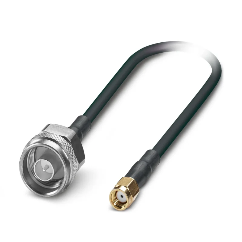
The first support point is not simply “as close as possible.”
A clamp placed too close may block coupling-nut movement, torque-wrench access, BNC bayonet rotation, inspection, or maintenance. It may also compress the boot or force a bend at the boot edge.
A clamp placed too far away leaves a long free span that acts as a lever.
Preserve connector and tool access
The finished design must allow the connector to be mated, torqued, cleaned, inspected, and removed. Include the real tool envelope and adjacent connectors in the layout review.
An SMA support arrangement that looks acceptable in a flat drawing may become unusable once the torque wrench and neighboring ports are included.
Leave a controlled transition
Separate these dimensions:
- Connector exit length
- Boot length
- Straight relief allowance
- First allowable bend
- Clamp centerline
- Service-access allowance
The bend should begin after the termination transition, not inside the crimp or at the hard edge of the boot.
Avoid creating a new hinge
A clamp installed directly against a stiff boot can create two rigid zones with a narrow flexible point between them. Under vibration, the cable then fails at the boot exit.
Check whether the cable forms a smooth curve, whether the boot edge acts as a hinge, whether the clamp causes reverse bending, and whether the jacket contacts a hard enclosure edge.
Calculate a practical support position
Use this project-planning formula:
Dsupport =Lconnector exit+ Lboot+ Lstraight relief It organizes the geometry but is not a universal standard. The final location must still satisfy bend radius, tool access, cable weight, and vibration requirements.
How Tight Can a Coax Cable Clamp Be?
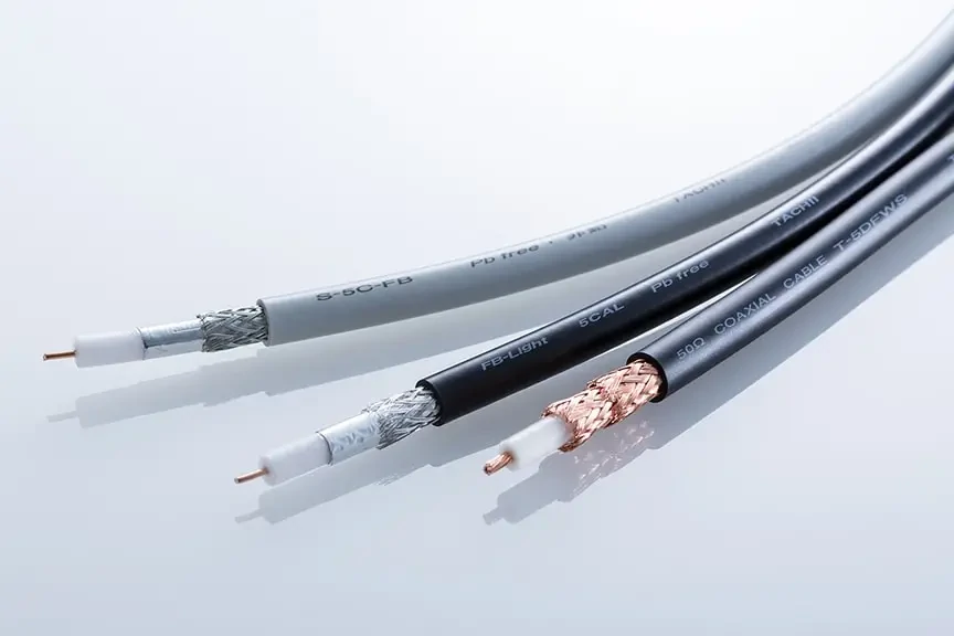
Comparison of coax cable structures including conductor, dielectric, shielding braid, and jacket layers. Cable construction influences mechanical support selection.
A clamp must stop harmful movement without crushing the cable.
Coaxial geometry depends on the relationship between the center conductor, dielectric, and shield. Excessive compression can disturb that geometry even when continuity remains normal.
Match the clamp to the finished OD
Confirm nominal and maximum cable diameter, jacket material, compressibility, sleeve or overmold diameter, temperature expansion, and clamp tolerance.
Do not size a clamp from the RG designation alone. Different manufacturers can use different jacket constructions for nominally similar cable families.
Watch for over-clamping and under-clamping
Over-clamping may cause jacket indentation, shield deformation, dielectric compression, local impedance change, and return-loss variation.
Under-clamping may allow sliding, abrasion, repeated impact, connector loading, and movement noise.
For vibration-prone equipment, a lined clamp is often useful, but the liner does not replace dimensional control.
Specify retention, not vague screw torque
“Tighten securely” does not define an acceptable assembly.
Specify maximum cable movement, minimum retention force, no visible jacket damage, no connector rotation, fastener security, and no measurable RF change after loading. The clamp screw torque can then be developed for the selected hardware and mounting surface.
Coax Cable Clamp Sizing Matrix
| Item | Required Value |
| Cable nominal and maximum OD | mm |
| Sleeve or boot OD | mm |
| Clamp internal diameter | mm |
| Liner | None/Rubber/Silicone/Other |
| Jacket material | FEP/PVC/PE/PUR/Other |
| Maximum cable movement | mm |
| Jacket indentation | None or project limit |
| Retention test | Pull/Slide/Vibration |
| Result | Approve/Resize/Reline |
Can the Cable Meet Its Bend Radius After Support Is Added?
A support point can solve a weight problem and create a bend problem.
Before the clamp is installed, the cable may form a broad curve. After installation, the curve can move toward the connector, become tighter, or reverse direction.
Separate installation radius from repeated-flex radius
Datasheets may distinguish one-time installation bend radius, repeated bend radius, continuous-flex use, and cable-chain use.
Do not apply a one-time forming limit to a cable that will move repeatedly. A standard RG316 jumper may be flexible, but that does not make it a high-cycle robotic cable.
Check the final installed shape
Verify that the first bend does not begin inside the crimp, at the boot edge, or against a sharp enclosure surface. Confirm that a cover, heat sink, adjacent harness, or later connector rotation does not reduce the available radius.
The final installed assembly matters more than the flat drawing.
Use a routing gauge
Incoming and assembly inspection can use a printed radius template, go/no-go bend gauge, CAD envelope, inspection photograph, or approved first article.
A useful bend-radius gate records the cable datasheet limit, actual installed radius, first-bend distance, boot-edge hinge risk, enclosure contact, and final pass or reroute decision.
When Is a Boot Better Than Heat Shrink or a Spring Guard?
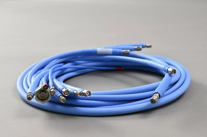
Multi-channel coaxial cable assembly used in RF testing systems. Cable routing and strain relief are important for maintaining mechanical and electrical performance.
The best method depends on the load and production process.
Molded boot
A molded boot offers repeatable geometry, controlled stiffness, and a defined transition. It suits production assemblies that need consistent flex behavior, integrated sealing, or permanent identification.
Verify material, temperature range, chemical resistance, cable adhesion, connector adhesion, maximum diameter, and flexibility after aging.
Adhesive-lined heat shrink
Heat shrink suits sealing, jacket reinforcement, low-volume customization, and moderate transition support. Risks include excessive stiffness, adhesive wicking, incorrect recovery ratio, heat damage, and poor adhesion to some fluoropolymer jackets.
Spring guard
A spring guard is useful for bench leads, handheld equipment, and repeated local bending. The spring end must not abrade the jacket, trap contamination, detach, or create a kink at its exit.
Braided sleeve or overmolding
Braided sleeve improves abrasion resistance and bundle control. Overmolding can combine gripping, sealing, labeling, and flex transition. Neither should be specified for appearance alone.
| Method | Flex Control | Pull Support | Sealing | Typical Use |
| Molded boot | High | Medium | Medium/High | Production assembly |
| Heat shrink | Medium | Low/Medium | High with adhesive | Sealing and reinforcement |
| Spring guard | High | Low | Low | Repeated handling |
| Braided sleeve | Medium | Medium | Low | Abrasion protection |
| Cable clamp | Indirect | High | Low | Structural support |
| Bulkhead/bracket | Indirect | High | Project-dependent | Load transfer to enclosure |
How Should RG174, RG316, RG58, and Larger Coax Be Supported?
Cable family changes the mechanical risk.
RG174 and miniature coax
Miniature coax is light and easy to route, but the small termination area is vulnerable to sharp localized bending. Use a small flexible boot, gentle service loop, lightweight support, and no overtight cable ties.
RG316 strain relief
RG316 strain relief is common in SMA jumpers, GNSS antenna leads, internal panel pigtails, and laboratory harnesses.
The important points are a smooth connector transition, controlled first bend, support before a long unsupported run, and no torsion during SMA mating. A sample that works straight on a bench may behave differently after it is bent into a compact enclosure.
RG58 support
RG58 is heavier and larger. It can place substantial leverage on a PCB SMA port. Review cable weight, panel strength, clamp position, bend space, vibration, and service access.
A short boot behind the connector does not replace a structural support farther down the cable.
Large low-loss coax
LMR-240, LMR-400, and similar large cable generally require feeder clamps, bulkhead transitions, rack or wall support, and multiple support points.
Where a small SMA interface must connect to a large feeder, use a supported transition rather than hanging the feeder directly from the SMA port.
What Changes in Vibration, Vehicle, and Outdoor Service?
A design that works on a stationary bench may fail in a vehicle or exposed enclosure.
Prevent the support point becoming a vibration hinge
Review clamp stiffness, free-span length, cable resonance, bracket movement, enclosure contact, connector rotation, and motion at the boot edge.
The support should reduce movement without concentrating every vibration cycle at one location.
Add anti-rotation control in vehicles
Vehicle installations combine vibration, impact, temperature cycling, maintenance movement, and connector loosening.
A robust layout may use a lined clamp, anti-rotation bracket, secondary support, controlled service loop, locked routing, and post-vibration RF verification.
Separate outdoor sealing from structural support
Outdoor systems may need weather sealing, UV-resistant jacket, drip loop, wind support, grounding, and water-entry control.
Waterproof tape or adhesive heat shrink protects against moisture. It does not automatically support cable weight.
The drip loop must also satisfy the cable bend radius. A tight loop can improve water management while shortening cable life.
Protect test cables with a defined flex zone
Repeated movement should not occur at the ferrule, crimp sleeve, boot edge, instrument port, or adapter interface.
Create a large supported arc or replaceable wear section. For phase-sensitive test cables, compare phase and loss before and after flexing instead of checking continuity alone.
How Do Connector Styles Change the Support Strategy?
SMA
The main risks are port leverage, cable twist, limited wrench clearance, and PCB loading.
Hold the connector body where required, rotate the coupling nut rather than the cable, support RG58 or larger cable, and consider a panel bulkhead for external loads.
BNC
BNC needs bayonet rotation clearance. The support should allow mating and removal while preventing the cable from hanging from the panel interface.
TNC and N-type
These connectors often use heavier cable. Review threaded mating torque, connector weight, feeder load, panel strength, clamp spacing, and weather sealing.
A strong connector body does not mean the port should support an entire feeder run.
MCX and MMCX
Do not remove snap-on connectors by pulling the cable. Use lightweight nearby support, limit side loading, and consider a panel transition where users need frequent external access.
How Can You Prove the Strain Relief Works?
Mechanical appearance is not enough. Verification should combine baseline measurements, mechanical loading, and post-test electrical checks.
Record the baseline
Before testing, record cable length, boot length, clamp position, bend radius, connector alignment, jacket condition, connector-body position, fastener condition, and routing photographs.
Define the coax cable pull test
A coax cable pull test must state pull direction, force, ramp rate, hold time, number of cycles, connector mating condition, and pass/fail criteria.
Do not use one arbitrary force for every RG174, RG316, and RG58 assembly. The requirement should reflect the actual termination and service risk.
Add side-load, torsion, and flex tests
Where relevant, test 90-degree side load, cable-axis torsion, connector rotation, clamp slippage, jacket indentation, repeated access, and flexing at the intended service radius.
Repeat RF measurements
Compare continuity, shield continuity, isolation, S11, S21, VSWR, insertion loss, and phase stability where required.
Continuity alone is insufficient. The assembly may remain connected while RF performance changes because the dielectric, braid, or center conductor moved.
Reject momentary opens, S11 spikes during movement, S21 fluctuation, connector noise, cable-position sensitivity, and permanent result shift. A reading that recovers after the cable is released is still evidence of a mechanical problem.
Coax Strain-Relief Acceptance Protocol
| Stage | Required Record |
| Initial inspection | Photos, dimensions, jacket condition |
| Initial electrical test | Continuity, S11, S21 |
| Axial pull | Force, direction, hold time |
| Side load and torsion | Force, angle, or torque |
| Flex or vibration | Radius, cycles, profile, duration |
| Mechanical result | Clamp movement, connector rotation, damage |
| Post-test RF result | Change in S11, S21, VSWR, or phase |
| Decision | Approve/Reject/Redesign |
What Should the Drawing and RFQ Lock Down?
The RFQ should define the complete construction, geometry, mechanical loads, and test method.
Specify Connector A, Connector B, cable type, finished OD, impedance, overall length, termination method, operating frequency, boot material, boot length, clamp type, support distance, bend radius, and environmental exposure.
Dimension the boot start and end, first-bend distance, clamp centerline, unsupported span, cable exit angle, and service loop.
State axial pull, side load, torsion, flex cycles, vibration, mating cycles, and cable weight. Link mechanical and electrical acceptance with wording such as:
A practical BOM or RFQ line may read:
SMA male to SMA female RF cable assembly, 50 ohm, RG316 cable, specified overall length, molded rear boot, first support point dimensioned from connector reference, minimum installed bend radius stated on drawing, axial pull and flex test required, S11 and S21 verified before and after mechanical testing.
This is far more useful than “SMA cable with strain relief.”
When Should the Enclosure Carry the Load Instead?
Sometimes the correct solution is a different architecture.
Use a panel bulkhead for repeated external mating, external antennas, vehicle radios, test access ports, and user-serviceable cables. Use a support bracket for RG58 or larger cable, vertical runs, rack installations, and vibration.
A service loop is useful where controlled movement is unavoidable, but it must satisfy bend radius, stay clear of sharp or hot parts, prevent maintenance tension, and avoid uncontrolled vibration.
Redesign the system when a secure clamp cannot be mounted, the cable must bend immediately at the connector, heavy cable attaches directly to a PCB SMA port, multiple rigid adapters are required for routing, or the cable must be twisted during maintenance.
Strain relief should not hide an architecture that is mechanically wrong.
FAQ
Can heat-shrink tubing alone provide strain relief for RG316?
It can reinforce and seal the connector transition, but it may not support a long cable or remove side load from the SMA termination. Where cable weight, pulling, or vibration reaches the connector, add a clamp, bracket, or bulkhead. The tubing type, recovery ratio, adhesive, and finished stiffness should also be specified.
Does a bulkhead eliminate the need for internal support?
Not always. The bulkhead transfers external load into the panel, but a long, heavy, vibrating, or sharply routed internal pigtail may still require support.
What should be checked after a pull or flex test?
Inspect connector rotation, clamp movement, boot separation, jacket damage, braid exposure, cable pullout, and bend geometry. Then repeat continuity, return loss, insertion loss, and phase measurements where required. Compare them with the pre-test baseline.
A reliable coax cable strain relief design begins with the installed load path, not a boot catalog.
For a custom assembly, provide the cable type, connector interfaces, finished OD, operating frequency, first-bend space, support location, expected pull or vibration, environmental conditions, and post-test RF limits. That information allows the supplier to design a real load-control system instead of adding a generic sleeve that only looks protective.
