
A cable assembly can pass continuity and still be the wrong RF part.
That is where many antenna projects go sideways. The connector screws on. The cable length looks close. The first sample may even work during a quick bench check. Then the same coax antenna cable performs poorly after installation because the cable is longer, routed tighter, connected through an adapter, or paired with the wrong antenna port.
For RF antenna links, the cable is not just a piece of wire between two ends. It becomes part of the signal path. Cable type, impedance, connector geometry, shielding, routing, and test requirements all affect how much useful signal reaches the antenna or receiver.
This guide focuses on practical selection. It is written for engineers and buyers who need to specify an antenna coax cable clearly enough for sourcing, production, and inspection.
How Should a Coax Antenna Cable Be Planned for an RF Link?
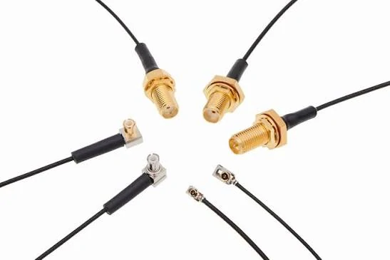
Overview of RF coaxial cable connectors used in antenna cable assemblies. Selecting the correct connector requires matching interface type, impedance, frequency range, and application requirements.
Where does the cable begin? Where does it end? Is it inside an enclosure, between a PCB and panel antenna, from a router to an external antenna, or from outdoor equipment back to a device cabinet? A short internal jumper and a long outdoor antenna run may both be called “antenna cable,” but they do not have the same sourcing risk.
A short RF module-to-antenna cable usually needs compact routing, correct connector fit, and stable termination. A longer outdoor cable needs lower attenuation, stronger shielding, better jacket durability, and more attention to connector sealing. If the same part number is used for both situations, one of the applications may be compromised.
The basic planning question is simple:
Will the cable be used as a small internal jumper, a device-to-antenna extension, or a longer RF feed line?
That answer changes almost everything.
Define the cable path between the RF device and antenna
For a coax antenna cable, length should not be treated as a mechanical afterthought. Every extra centimeter adds some loss, and the loss becomes more visible as frequency rises. In WiFi, GPS, LTE, IoT, and RF test setups, a cable that looks “not very long” can still affect the link if the signal is weak or the system has little margin.
Buyers often send a request such as:
“Need SMA antenna cable, 1 meter.”
That is not enough for a safe RF quotation. A better request would include:
SMA male to N female, 50 ohm, RG316 or low-loss coax, 1 meter, used for 2.4 GHz antenna connection, continuity test required, VSWR test preferred.
This gives the supplier enough context to check cable compatibility, connector body size, impedance, and test expectation. It also helps avoid quiet substitutions, such as changing the cable family because the connector interface looks the same.
Explain why coax structure is suitable for antenna signal transmission
A coax cable has a center conductor, dielectric layer, shield, and outer jacket. That structure helps carry RF energy along a controlled path while reducing unwanted leakage and external interference. For antenna work, that matters because the cable is often routed near power wiring, metal housings, PCB edges, outdoor enclosures, or other RF paths.
The shield is not only a “protection layer.” It is part of the RF return path. Poor braid contact, damaged shielding, incorrect crimping, or an unsuitable connector rear body can change the behavior of the cable assembly even when the front connector mates correctly.
This is also why a generic electrical cable cannot replace a coax antenna cable in RF service. The cable may conduct DC or low-frequency signals, but it will not provide the same impedance control or shielding behavior.
For more background on common RG cable families, the TEJTE RG cable guide is useful when comparing cable size, flexibility, and application fit.
Separate coax antenna cables from generic antenna cables
The phrase “antenna cable” can be vague. In some markets, it may refer to TV coax, RF antenna leads, wireless router extensions, GPS antenna pigtails, or even non-coaxial antenna wiring. For RF sourcing, the term should be tightened.
A coax antenna cable normally means the cable is expected to carry RF signal between the device and antenna while maintaining impedance, shielding, and connector compatibility. That does not automatically mean it is high-frequency or low-loss. It only means the structure is suitable for RF antenna transmission when the cable type and connectors are correctly specified.
A small U.FL to SMA jumper for an IoT enclosure and an N type outdoor antenna cable may both be coax antenna cables. Their risk points are different. The small jumper may fail because of bending, connector handling, or weak crimping. The outdoor cable may fail because of loss, moisture entry, jacket aging, or poor strain relief.
Use the table below as a simple planning asset before selecting the cable family.
| Signal Path | Cable Role | Main Check |
| RF module → antenna | Short internal RF link | Connector + impedance |
| Router → external antenna | Wireless extension | Cable loss |
| GPS receiver → antenna | Weak signal path | Low loss + shielding |
| Outdoor antenna → device | Longer RF run | Cable attenuation + jacket |
| Test device → antenna | Temporary setup | VSWR + connector fit |
This table does not replace a datasheet. It prevents the first sourcing mistake: treating all antenna cables as the same part with different ends.
How Do You Match Coax Cable, Antenna Port, and RF Device Interface?
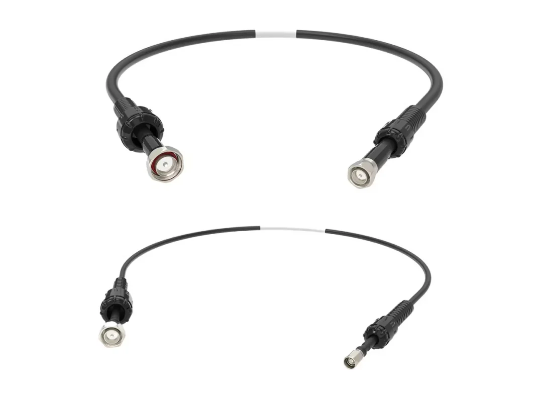
Antenna cable matching starts at the interfaces, not at the product photo.
Two connectors may look similar but have different gender, polarity, impedance, or usable frequency range. SMA and RP-SMA are a common example in wireless devices. They may share thread dimensions, but the center contact arrangement is different. A cable that appears close in a photo may not mate correctly, or it may mate in a way that creates sourcing confusion later.
For replacement orders, the safest approach is to confirm both ends with photos, drawings, or an existing sample. For new designs, specify the device-side connector, antenna-side connector, impedance, cable type, and frequency range before asking for price.
Confirm the antenna connector before selecting the cable
The antenna side often creates more mistakes than the device side. Outdoor antennas may use N type connectors. Compact antennas may use SMA, RP-SMA, U.FL, MMCX, or other small RF interfaces. Test equipment may use SMA, BNC, TNC, N type, or precision connectors depending on the setup.
Do not describe only the thread.
A correct connector description should include:
Connector series, gender, polarity if applicable, impedance, mounting style, and mating side.
For example, “SMA female” is clearer than “SMA head.” “RP-SMA female bulkhead” is clearer than “WiFi antenna connector.” “N female panel mount, 50 ohm” is better than “large outdoor antenna port.”
Small wording differences can change the part.
Match the device-side connector with the antenna-side connector
After the antenna connector is confirmed, match the other end to the RF device. This is where custom cable assemblies are often needed. A device may use a small board connector internally while the enclosure needs an SMA or N type external antenna interface. In that case, the cable assembly is doing both electrical and mechanical work.
A common example is a short internal jumper from U.FL or MHF series to SMA bulkhead. Another is an SMA male to N female antenna extension for a wireless or RF test system. The correct assembly depends on the cable diameter, ferrule size, center pin, crimp process, and strain relief. The front connector name alone does not define the complete part.
If the cable must pass through a panel, enclosure wall, or waterproof gland, include that information before ordering. The supplier may need to check thread length, nut position, washer stack, gasket compression, and bending space behind the connector.
Avoid choosing only by cable appearance or thread size
The most expensive mistake is not always a visibly wrong connector. Sometimes the assembly mates, but the RF behavior is poor.
A continuity test checks whether the center conductor and shield are connected correctly. It does not confirm insertion loss, return loss, VSWR, or behavior at the target frequency.
Use this checklist when preparing an RFQ.
| Check Field | Requirement |
| Device Port | SMA / BNC / N Type / TNC / U.FL / Other |
| Antenna Port | SMA / N Type / RP-SMA / Other |
| Connector Gender | Male / Female |
| Polarity | Standard / Reverse polarity if applicable |
| Impedance | 50Ω / 75Ω |
| Frequency Range | MHz / GHz |
| Cable Length | mm / m / ft |
| Cable Type | RG316 / RG58 / RG174 / low-loss coax / specified |
| Application | WiFi / GPS / IoT / RF / Outdoor |
| Drawing or Photo | Required for replacement or custom build |
| Test Requirement | Continuity / VSWR / insertion loss / return loss |
A clear RFQ reduces back-and-forth and lowers the chance of a wrong substitution. It also gives production a better inspection target. Without that target, the supplier may only check the cable mechanically and electrically, while the buyer expects RF behavior that was never specified.
How Should SMA, N Type, BNC, and TNC Ends Be Selected?
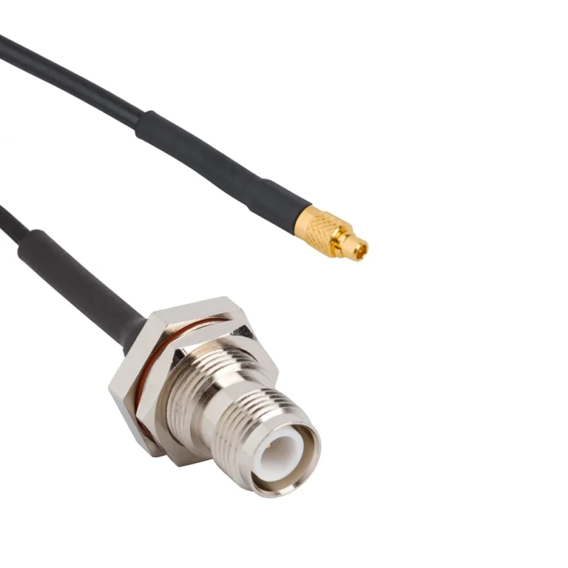
The connector end should be selected after the antenna path is understood, not before.
A buyer may start with “SMA cable” because the device has an SMA-looking port. That is only one part of the decision. The cable rear body must match the cable diameter. The center pin must match the conductor size. The connector rating should have enough margin for the working frequency. The mating side must also match the antenna or device port without relying on guesswork from photos.
For coax antenna cable assemblies, SMA, N Type, BNC, and TNC connectors are common because they cover many compact, outdoor, test, and rugged RF links. They are not interchangeable by habit. Each one solves a different mechanical and RF problem.
Use SMA ends for compact WiFi, GPS, and RF modules
SMA is often used where the cable assembly needs a compact threaded RF interface. You see it on WiFi antennas, GPS devices, RF modules, small test fixtures, and enclosure feedthroughs. It is small enough for limited panel space but still gives a more stable mechanical connection than a simple snap-on miniature connector.
The risk is assuming every SMA connector is the same.
A straight SMA male plug for RG316 is not automatically suitable for RG58. The cable diameter, dielectric size, ferrule, and center contact are different. A connector that crimps well on one cable can be loose, over-compressed, or poorly shielded on another. At low frequency, the problem may hide. At higher frequency, the same assembly may show poor VSWR or inconsistent insertion loss.
SMA also needs a polarity check. Standard SMA and RP-SMA are commonly confused in wireless antenna orders. The outer thread may look familiar, but the center contact arrangement changes. If the application is WiFi, always confirm whether the antenna side is SMA or RP-SMA before ordering the cable.
A practical BOM note is better than a short name:
SMA male to SMA male antenna coax cable, 50 ohm, RG316, 300 mm, for 2.4 GHz wireless module, standard polarity, continuity test required.
That is much safer than “SMA antenna cable.”
Use N Type ends for outdoor antenna and longer RF links
N Type connectors are usually selected when the antenna link needs stronger mechanical structure, larger cable compatibility, or outdoor installation tolerance. They are common on outdoor antennas, base-station-related equipment, cabinets, and longer RF cable runs.
The useful point is not only that N Type is physically larger. Its size allows better support for thicker low-loss coax in many antenna systems. If the cable run is several meters, the cable may become the main source of loss. In that case, using a very thin cable just because it is flexible can reduce antenna system performance more than expected.
Outdoor N Type cable assemblies should also be checked for sealing, strain relief, and jacket suitability. A connector may be rated for outdoor use, but the full assembly still depends on rear termination, heat shrink, boot design, panel mounting, and installation direction. If water can collect near the connector body or enter through the cable jacket, electrical performance may change after field exposure.
For longer runs, buyers should specify the cable family clearly: RG58, RG142, LMR-type low-loss cable, semi-flexible cable, or a custom low-loss coax. If the supplier changes cable type to fit stock availability, the RF result may not match the original requirement.
Use BNC or TNC ends for test setups and rugged RF environments
BNC is common in test equipment because it is quick to connect and disconnect. That makes it useful for lab setups, temporary antenna tests, low-to-mid-frequency RF checks, and instruments where repeated handling matters. The trade-off is that the bayonet style is not the best choice for every vibration or outdoor situation.
TNC uses a threaded coupling style. It is often preferred where a more secure connection is needed, especially when the cable may experience movement, vibration, or field handling. TNC can look like a more rugged cousin of BNC, but the selection still depends on impedance, cable type, frequency range, and the exact antenna or device port.
For procurement, the mistake is treating BNC and TNC as only mechanical formats. A 50 ohm RF cable assembly and a 75 ohm video or broadcast-style cable assembly may look similar to a non-RF buyer. They should not be mixed without checking the system impedance.
The table below gives a practical first-pass selection view.
| Connector End | Better For | Main Selection Factor | Common Risk |
| SMA | WiFi, GPS, compact RF modules | Small size and threaded mating | Confusing SMA with RP-SMA |
| RP-SMA | Some wireless antennas | Polarity confirmation | Wrong center contact |
| N Type | Outdoor antenna and longer runs | Mechanical strength and cable size | Ignoring sealing or cable loss |
| BNC | Test equipment and temporary setups | Fast connection | Wrong impedance or frequency assumption |
| TNC | Rugged RF systems | Threaded locking | Treating it as interchangeable with BNC |
This table is not a substitute for the datasheet. It is a way to stop the wrong connector family from entering the quotation stage.
How Do Length, Frequency, and Routing Change Antenna Cable Loss?
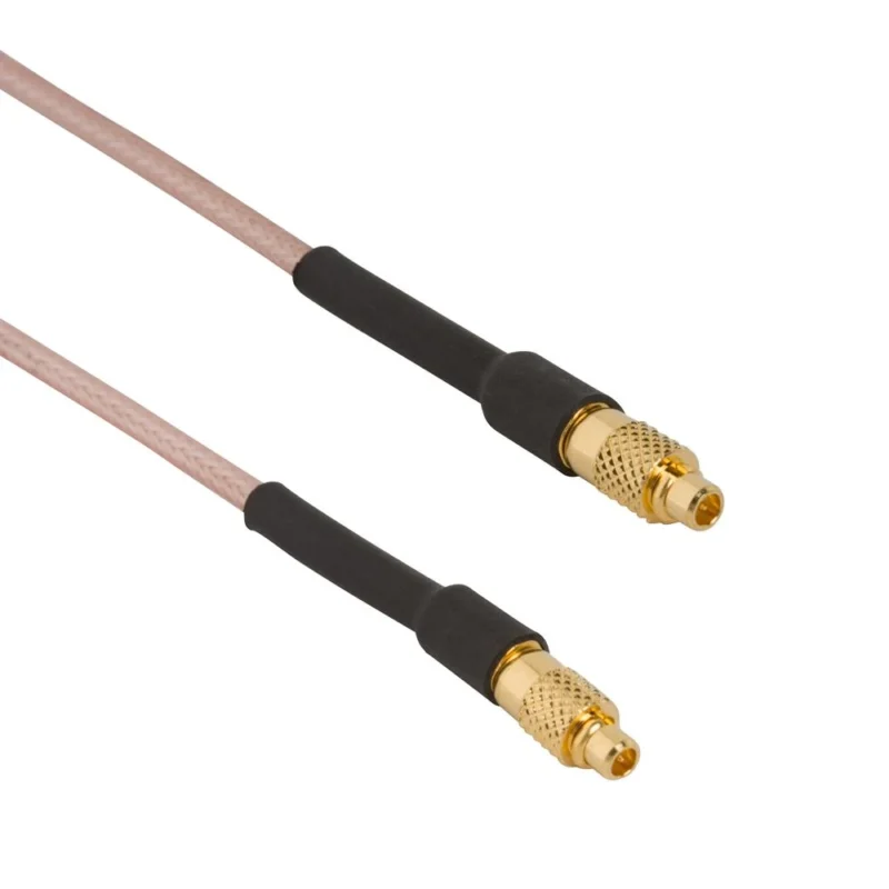
Antenna cable loss is quiet. It does not always create a visible failure.
The device powers on. The antenna is connected. The cable passes continuity. But the received signal is weaker, the transmit range is shorter, or the VNA sweep shows more loss than expected. This often happens when length, frequency, routing, and adapter count were not estimated before the cable was purchased.
A coax antenna cable is part of the RF budget. The longer it is, the more attenuation it adds. The higher the frequency, the more sensitive the cable choice becomes. Thin flexible coax is useful inside small devices, but it is not automatically a good choice for a long outdoor antenna run.
Compare short indoor cables with longer outdoor antenna runs
A 150 mm internal cable and a 5 m antenna extension should not be selected with the same logic.
For a short indoor jumper, the main concerns may be connector fit, bend radius, crimp quality, and repeatable assembly. Cable loss may still matter, but the length is short enough that mechanical details can dominate the risk.
For a longer antenna run, attenuation usually moves to the front of the decision. Low-loss antenna cable may be needed, especially at higher frequency or when the system already has limited signal margin. The cable may also need a tougher jacket, better shielding, and connector sealing suitable for the installation environment.
A buyer should avoid asking only for “the cheapest 5 meter SMA antenna cable.” That request usually pushes the supplier toward a thin, flexible cable that may be convenient to build but not suitable for the RF path. A better request states the operating band, maximum length, connector ends, and whether low loss is required.
Leave margin for connectors, adapters, and cable bends
Adapters are convenient, but they are not free in RF terms. Every added interface can introduce extra mismatch, mechanical tolerance, and loss. One adapter may be acceptable. Several adapters stacked together can turn a clean antenna path into an unstable one.
Cable bends are another quiet problem. A cable routed tightly behind a panel connector may pass incoming inspection and fail later after the enclosure is assembled. Bending can disturb the dielectric, shield contact, or termination area, especially on small flexible coax.
For production, the cable drawing should show more than length. It should include connector orientation, heat shrink position, panel nut position if applicable, and any routing constraints. For RF-sensitive projects, the inspection requirement should also state whether the cable is checked only by continuity or by VSWR, insertion loss, or return loss at the target frequency.
Before approving a coax antenna cable for batch production, write the RF requirement in a way production can inspect:
50 ohm antenna cable assembly, SMA male to N female, 1 m, target band 2.4 GHz, continuity 100%, visual inspection 100%, VSWR test by sampling or full test as required.
That kind of note is not complicated. It prevents the cable from being treated as a generic wire harness.
How Can Shielding and Jacket Choices Protect Antenna Signal Paths?
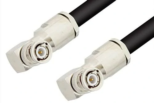
TNC connector cable assemblies are commonly used in communication systems, outdoor antenna equipment, and RF applications where stable connections are required.
Shielding is easy to underestimate because it does not look like an active RF feature. It sits inside the cable, out of sight, until the antenna link is routed near a power module, motor driver, metal frame, switching supply, or another RF path.
For a coax antenna cable, shielding affects more than noise resistance. It also supports the RF return path. If the braid is damaged, poorly crimped, or not matched to the connector rear body, the cable may still pass continuity while showing unstable RF behavior.
Choose shielded antenna cables for noisy RF environments
A simple antenna jumper inside a clean plastic enclosure may not need the same shielding as a cable routed through an industrial cabinet. In noisy environments, better shielding can help reduce external interference and signal leakage.
Select jacket material based on indoor, outdoor, or enclosure use
For outdoor antenna cables, jacket durability, UV exposure, moisture protection, and connector sealing become more important. For equipment installed inside a metal enclosure, the cable may need to survive compression, edge contact, and repeated maintenance movement.
A cable that works well on the bench can fail after being tied too tightly, bent near the connector, or routed through a sharp panel opening. These are installation problems, not only cable problems.
Balance flexibility, shielding, and low-loss requirements
There is no free cable choice. Thin cable is flexible but usually has higher attenuation. Low-loss cable is useful for longer antenna runs, but it may be larger and harder to route.
Use this table before locking the cable type.
| Requirement | Recommended Direction | Main Trade-Off |
| High EMI area | Double-shielded coax | Larger OD, less flexible |
| Outdoor antenna | Rugged jacket + sealed connector | Higher cost, larger assembly |
| Compact routing | Flexible small coax | Higher loss over distance |
| Long antenna run | Low-loss coax | Harder routing, larger bend radius |
| Repeated movement | Flexible jacket + strain relief | Needs better mechanical design |
The correct choice depends on the antenna path, not on one cable parameter alone.
How Do WiFi, GPS, IoT, and Outdoor Antennas Need Different Cables?
A WiFi antenna cable, a GPS antenna cable, and an outdoor antenna cable may all be coaxial. That does not make them interchangeable.
Each application has a different weak point. IoT devices usually have very limited routing space. Outdoor antennas add cable length, moisture, and mechanical exposure.
Select WiFi antenna cables for routers and wireless modules
WiFi antenna cables often use SMA, RP-SMA, U.FL, MHF, or similar compact RF interfaces. The most common mistake is polarity confusion between SMA and RP-SMA. Another common mistake is using a long thin cable because it is easy to buy, then discovering that the signal loss is too high.
For short internal WiFi jumpers, focus on connector fit, cable routing, and crimp quality. For external WiFi antenna extensions, check cable length and frequency band before selecting the cable family.
Select GPS antenna cables for navigation and tracking devices
GPS antenna links need more care because the received signal is usually weak. A poor cable choice, loose connector, damaged shield, or unnecessary adapter can reduce the margin.
The buyer should confirm whether the antenna is active or passive, the connector type, cable length, impedance, and installation environment. If the cable is routed near a noisy power supply or inside a vehicle, shielding and strain relief should not be ignored.
Select coax antenna cables for outdoor and communication antennas
Outdoor antenna cables usually need lower loss, stronger jacket protection, and better mechanical sealing. The longer the cable run, the less acceptable it is to choose only by connector type.
For example, an N Type connector may be suitable for outdoor antenna equipment, but the assembly still needs the right cable, termination, weather protection, and installation direction. A poor rear seal can let moisture enter even when the front interface looks rugged.
| Application | Cable Priority | Common Connector | Selection Risk |
| WiFi router | Flexibility + connector fit | SMA / RP-SMA | Polarity mistake |
| GPS device | Low loss + shielding | SMA / U.FL | Weak signal margin |
| IoT terminal | Compact routing | U.FL / MHF / SMA | Tight bend stress |
| Outdoor antenna | Low loss + durability | N Type / TNC | Moisture and attenuation |
| RF test setup | Repeatability | SMA / BNC / N Type | Adapter stack loss |
This matrix is useful for early selection. Final approval should still be based on the actual operating frequency, length, connector drawings, and inspection target.
How Should Coax Antenna Cable Assemblies Be Tested and Specified?
Testing should match the risk of the application.
For simple low-risk orders, continuity and visual inspection may be enough. For RF-sensitive antenna links, that is not enough. A cable can have correct electrical continuity but still show poor insertion loss, high VSWR, or unstable return loss near the target band.
Request continuity and visual inspection for basic orders
Continuity testing confirms that the center conductor and shield are connected correctly and not shorted. Visual inspection checks connector damage, crimp position, heat shrink, cable jacket, labeling, and length.
These are basic checks. They should be done for normal antenna cable assembly orders.
Add VSWR, insertion loss, and return loss for RF-sensitive projects
If the cable is used near the upper frequency range, in weak-signal reception, in RF test equipment, or in batch production, define the RF test requirement before ordering.
Do not write only “test before shipment.” That is too vague.
A better note is:
50 ohm coax antenna cable assembly, SMA male to SMA male, RG316, 300 mm, target frequency 2.4 GHz, continuity 100%, visual inspection 100%, VSWR sampling test required.
For stricter projects, define whether insertion loss or return loss should be tested at one frequency point or across a sweep range.
Provide cable length, connector details, impedance, and application before quotation
A clear RFQ saves time and reduces wrong substitutions.
| RFQ Field | Example |
| Application | WiFi / GPS / RF antenna / outdoor |
| Cable Type | RG316 / RG58 / low-loss coax |
| Connector A | SMA male |
| Connector B | N female |
| Length | 300 mm / 1 m / custom |
| Impedance | 50 ohm |
| Frequency Range | DC–3 GHz / DC–6 GHz |
| Shielding | Single / double / specified |
| Test Requirement | Continuity / VSWR / insertion loss |
| Quantity | Sample / batch |
| Drawing or Photo | Required for replacement |
For custom coax antenna cable assemblies, also provide panel thickness, nut position, cable exit direction, heat shrink requirement, label format, and packaging needs if they affect installation.
FAQ
Is a coax antenna cable the same as a regular coax cable?
Not exactly. A coax antenna cable is selected for antenna signal transmission. Connector type, impedance, frequency range, cable length, shielding, and installation environment matter more than they would for a generic coax request. The cable should be specified as part of the RF path.
What impedance should a coax antenna cable use?
Most RF antenna systems use 50 ohm cable, but the antenna, device port, cable, connector, and adapter should be checked together. Do not assume impedance from appearance. Some coax products and connectors may be 75 ohm for video or broadcast-style applications.
Does cable length affect antenna signal strength?
Yes. Longer coax antenna cables add more attenuation, especially at higher frequencies. For short internal jumpers, the effect may be small. For longer outdoor antenna runs, cable loss can become one of the main limits in the RF link.
Which connector is common for coax antenna cables?
SMA, RP-SMA, N Type, BNC, TNC, U.FL, and MHF-style connectors are common, depending on the device and antenna. SMA and RP-SMA need special care because polarity mistakes are common in wireless antenna orders.
When should I choose a low loss antenna cable?
Choose low loss antenna cable when the cable run is long, the signal is weak, or the system operates at a higher frequency. The trade-off is usually larger cable diameter, reduced flexibility, and stricter routing requirements.
