
A wire repair can look finished and still fail later.
The continuity tester beeps. The sleeve color looks familiar. The harness is taped back into place. Then the connection heats under load, pulls loose during vibration, or corrodes from the wire entry point after a few weeks outside. That is where many butt connectors fail: not because the part is complicated, but because the connector, wire size, crimp tool, and environment were never treated as one connection system.
Butt connectors are used for inline wire splicing, not for attaching a wire to a stud, screw, blade, or equipment terminal. That sounds simple, but it matters when a buyer is replacing a damaged harness, extending a low-voltage circuit, or ordering production assemblies from a supplier. A butt splice connector may be the correct choice for joining two conductor ends. It is not a substitute for a ring terminal, spade terminal, quick-disconnect terminal, or terminal block connection.
Where Do Butt Connectors Belong in a Wire-Splicing Job?
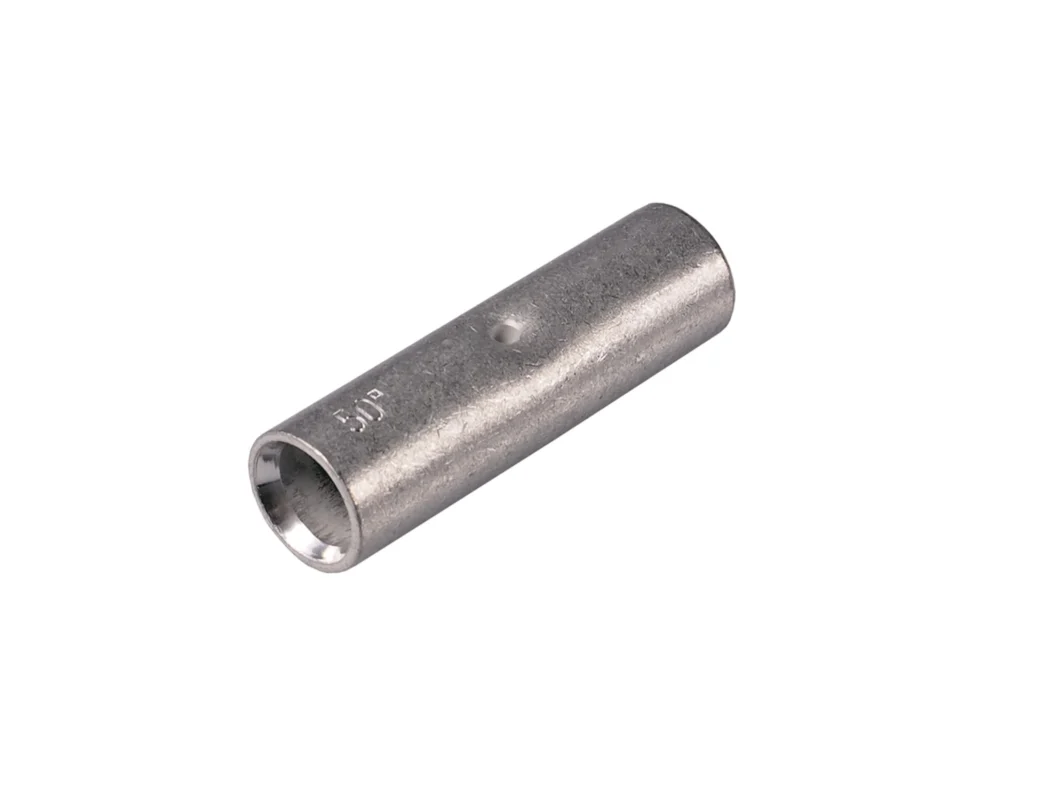
A butt connector sits in the middle of two prepared wire ends. Each conductor enters from one side, and the metal barrel is crimped around the stripped conductor. In a basic insulated design, the outside sleeve gives touch protection and helps position the wire. In a sealed design, the sleeve may also include adhesive or heat-shrink material that closes around the wire insulation.
The key parts are easy to miss:
- The barrel carries the electrical and mechanical connection.
- The insulation sleeve protects the crimped joint.
- The wire stop, if present, prevents one wire from passing too far through the connector.
- The two wire-entry paths must match the conductor and insulation size on both sides.
A common mistake is judging the connector by color alone. Red, blue, and yellow insulated butt connectors are common in the U.S. market, but color is not a specification. It normally suggests a wire range, yet the exact range can vary by manufacturer, insulation material, and connector series. For production purchasing, the marked AWG range and supplier drawing matter more than the sleeve color.
Identify the barrel, wire stop, insulation sleeve, and two-wire path
Look inside the connector before using it. A clean barrel should give enough insertion depth for the stripped conductor without requiring the installer to fold strands, trim copper, or force insulation into the crimp zone. If a wire stop is present, both wires should seat against it from opposite sides. If there is no visible stop, the installer needs a controlled strip length and insertion method.
That is especially important in harness production. Two operators can use the same connector and still produce different results if one strips too long and the other strips too short. Too much exposed copper creates a touch or corrosion risk. Too little stripped conductor leaves insulation inside the crimp area, which can pass a quick pull by hand but fail under load.
Separate inline splicing from wire-to-terminal connections
Use butt splice connectors when the job is wire-to-wire. Use terminal connectors when the job is wire-to-device.
A ring terminal belongs on a stud or grounding point. A spade or fork terminal fits a screw terminal where service access matters. A quick-disconnect terminal is used for plug-in equipment wiring. A butt connector does not create a serviceable endpoint; it creates a permanent inline splice.
This distinction helps prevent messy substitutions in purchasing. If a drawing says “wire splice connector,” the supplier should not automatically quote a terminal kit. If a repair instruction says “replace damaged section and splice inline,” the connector needs to match both wires, the crimp tool, and the working environment.
For a broader comparison of terminal styles, see the related guide on crimp connector tools and terminal selection.
Use butt splice connectors for extensions, repairs, and harness production
Butt connectors are common in electrical equipment repairs, automotive harness extensions, marine accessory wiring, low-voltage control circuits, lighting circuits, and production wire harnesses. They are useful when the goal is to restore conductor length or join two wire segments without adding a removable connector pair.
The job still needs limits. A small accessory circuit in a protected enclosure is not the same as a wet-location trailer harness. A low-current signal splice is not the same as a high-current DC feed. The same physical connector shape can appear in both settings, but the insulation system, conductor compatibility, temperature rating, and sealing method may be different.
Which Barrel and Insulation Design Fits the Job?
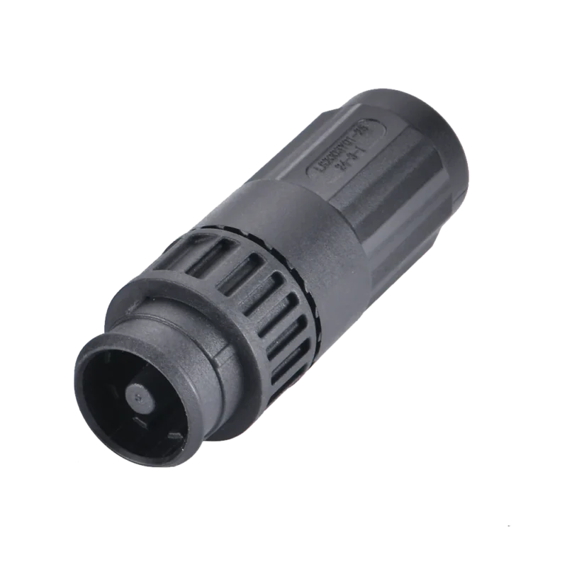
The barrel does the real work. Insulation makes the splice safer and easier to handle, but it does not fix a wrong crimp. A connector with a neat sleeve can still have low strand fill, a mismatched die mark, or poor conductor contact inside the barrel.
Select insulated butt connectors for protected dry-location circuits
Insulated butt connectors are often used in control cabinets, equipment wiring, vehicle interiors, and general repair work where the connection is protected from direct moisture. Vinyl and nylon sleeves are common. Nylon usually gives better toughness and temperature behavior than basic vinyl, but the final choice depends on the supplier’s rating and the job environment.
The important point: insulated does not automatically mean waterproof. A standard insulated butt connector may protect against accidental contact, but water can still enter from both wire-entry ends. In a dry enclosure, that may be acceptable. In a marine bilge, outdoor lighting run, trailer harness, or exposed vehicle underside, it usually is not enough.
Plan separate insulation around non insulated butt connectors
Non insulated butt connectors use a bare metal barrel without a built-in sleeve. They can save space and allow tighter process control, especially when the assembly will receive separate heat shrink tubing or when a production process requires visible barrel inspection before final insulation.
They also remove a layer of forgiveness. The operator must control strip length, crimp position, insulation recovery, and strain relief separately. If heat shrink is added later, it should cover the splice properly without hiding a bad crimp that should have been rejected first.
A non insulated butt connector can be a good choice in a controlled harness shop. It is less friendly for quick field repairs unless the installer has the correct tool, tubing, and inspection habit.
Treat waterproof and sealed designs as complete connection systems
Waterproof butt connectors and sealed butt connectors should be selected as a system: connector barrel, adhesive sleeve, wire insulation diameter, heat application, and final inspection all have to work together. If the sleeve is too large for the wire insulation, the adhesive may not seal. If the installer overheats one side and underheats the other, the splice may look acceptable while leaving a water path.
“Sealed,” “water-resistant,” and “waterproof” should not be treated as identical claims. For procurement, ask for the product drawing, supported wire insulation outside diameter, temperature range, and any relevant test or listing information. For installation, check both wire-entry points after shrinking. The sleeve should recover evenly, and adhesive-lined designs should show proper sealing behavior at the ends.
How Can You Match One Butt Connector to Two Wire Sizes?
The safest starting point is to read AWG range, barrel inside diameter, conductor area, and insulation size together. A butt connector that fits 16 AWG on paper may still be awkward if the wire insulation is unusually thick or the conductor is fine-stranded and fills the barrel differently from standard stranded copper.
Equal-gauge splices are usually straightforward: 16 AWG to 16 AWG, 18 AWG to 18 AWG, and so on. Unequal-gauge splices need more care. If the difference is small and both wires fall inside the listed range, the connector may be acceptable. If the difference is large, a step-down butt connector may be required.
Do not solve an oversized conductor by cutting away strands. That reduces conductor area and creates a weak point exactly where the splice should be strongest.
Read AWG range, barrel diameter, and conductor area together
Use this matrix before approving a connector for purchasing or production:
| Check Item | What to Confirm | Reject or Verify If |
| Wire A gauge | AWG or conductor area matches one side | Wire is outside marked range |
| Wire B gauge | Second wire also fits approved range | Different gauge is forced into same barrel |
| Conductor material | Bare copper or tinned copper is supported | Aluminum or mixed conductors are not listed |
| Strand class | Solid, stranded, or fine-stranded is approved | Fine strands spread or fold during insertion |
| Barrel inside diameter | Conductor fills barrel without forcing | Strands must be cut or folded |
| Strip length | Copper reaches proper barrel depth | Exposed copper remains outside sleeve |
| Tool and die | Crimp cavity matches connector series | Generic pliers or wrong cavity are used |
| Environment | Dry, vehicle, marine, or wet use is covered | Standard insulation is used as waterproofing |
This table is not a replacement for the manufacturer’s drawing. It is a purchasing filter. If any line is uncertain, the connector should be verified before it becomes a BOM item or repair standard.
For related connector comparisons, the parent guide on common wire connector types can help separate butt splices from terminals, twist-on connectors, push-in connectors, and other wire joining methods.
How Do You Build a Reliable Butt Splice from Start to Finish?
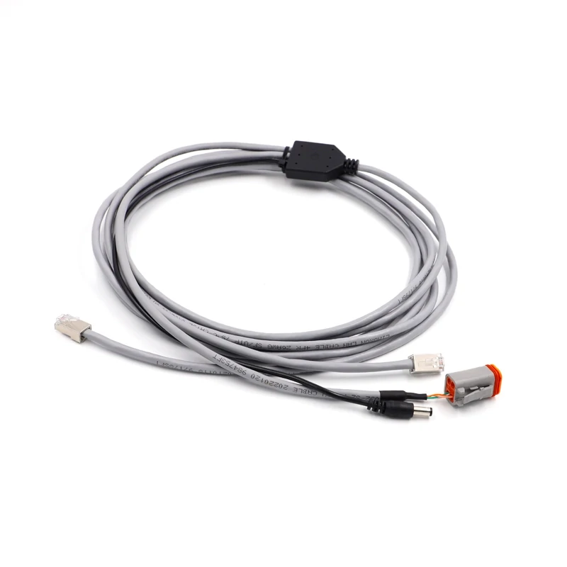
This wire harness demonstrates an application scenario of butt connectors in automotive electrical systems, where reliable crimping and proper sealing are important.
A good butt splice is not made at the crimping step alone. It starts before the connector touches the wire.
If the conductor is blackened, oxidized, water-stained, brittle, or missing strands, do not crimp over the damaged section. Cut the wire back until clean metal appears. This is a small decision, but it changes the whole repair. A connector can only grip the conductor that is inside the barrel; it cannot restore copper that has already lost strength or conductivity.
Cut back damaged wire before preparing the splice
Field repairs often fail because the installer tries to save wire length. That is understandable when the harness is short or hard to reach, but crimping onto damaged copper only moves the failure point into the connector. Corrosion under the insulation is worse because it may not be visible from the outside. If moisture has traveled along the strands, strip a little farther and inspect again.
For automotive butt connectors and marine butt connectors, this step matters even more. Vibration, temperature cycling, and moisture can turn a weak crimp into an intermittent fault. A splice that works during installation may fail after the harness is tied down, bent, or loaded.
Strip each conductor to the specified barrel depth
The strip length should match the effective barrel depth, not the total length of the plastic sleeve. If the connector has a center wire stop, each conductor should reach the stop without bunching. If there is no clear stop, use the supplier’s strip-length recommendation.
Too short is a mechanical problem. The crimp may land partly over insulation or capture only a small section of copper. Too long is an electrical and safety problem. Exposed conductor outside the sleeve increases the chance of shorting, corrosion, and failed inspection.
A practical production rule is simple: set the strip tool, check the first few pieces, and document the accepted strip length. Do not let each operator “feel” the length by eye.
Insert every strand without twisting away usable conductor area
Lightly gather loose strands if needed, but do not twist the conductor so tightly that it changes shape or becomes difficult to insert fully. Over-twisting can make fine-stranded wire behave like a stiff pin. It can also push strands backward when the wire enters the barrel.
Every strand should enter the connector. Folded-back strands reduce conductor area and may pierce insulation after crimping. Stray strands are also a warning sign that the barrel size, strip length, or insertion method is wrong.
This is where butt crimp connectors are less forgiving than they look. The outside sleeve hides the conductor once the wire is inserted. If the process is not controlled before crimping, the finished part may look cleaner than it really is.
Crimp both sides with the specified tool and die cavity
Use the crimp tool and die profile recommended for the connector series. A ratcheting crimp tool is preferred for repeatability because it controls the crimp cycle better than ordinary pliers. The correct die cavity should match the connector size, barrel type, and insulation style.
Crimp one side, then the other. Keep the connector seated in the die correctly, and place the crimp over the metal barrel area, not over empty sleeve material. For insulated butt connectors, the operator may not see the full metal barrel, so the tool position must be based on the connector design and manufacturer guidance.
After crimping, do not rotate the wire aggressively to “test” it. A controlled pull test is useful. Twisting and bending by hand can damage a splice that would otherwise pass its intended requirement.
For broader process guidance, see the related article on inspect other crimp terminal styles.
Add sealing and strain relief only when the connector design requires them
Heat should be used only when the connector is designed for heat-shrink recovery or adhesive sealing. Applying heat to a standard vinyl or nylon insulated butt connector can deform the sleeve, loosen the fit, or make the splice look artificially finished while adding no real seal.
For sealed butt connectors, heat from the center outward unless the manufacturer specifies another method. Watch both ends. The sleeve should recover around the wire insulation, and adhesive-lined connectors should show proper sealing at the entry points. If one side remains open, the splice is not sealed.
Strain relief is also part of the installation. A butt splice creates a rigid section in the wire. If the harness bends repeatedly right beside that rigid area, the conductor can fatigue at the sleeve edge. Support the harness so the splice is not carrying all the movement.
Why Does a Butt Splice Loosen, Heat Up, or Corrode?
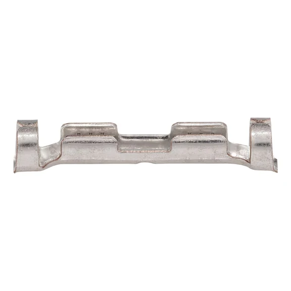
The metal contact element inside a butt connector creates the electrical path between two wires and must match the conductor size and crimping method.
A splice can pass continuity and still be wrong.
Continuity only proves that current can pass under a tiny test condition. It does not prove the crimp area is large enough, the resistance is low enough, or the splice can survive vibration and moisture.
Diagnose under-crimping, over-crimping, and the wrong die profile
Under-crimping leaves empty space between the conductor and barrel. The wire may pull loose, or the connection may develop high resistance under current. Over-crimping is not better. It can cut strands, crack the barrel, or create a sharp stress point.
The wrong die profile is harder to catch. A tool may squeeze the connector tightly, but not in the shape intended by the terminal design. That can create a crimp that feels strong by hand but does not meet the electrical or mechanical requirement.
Use this failure table during inspection or supplier feedback:
| Failure Symptom | Likely Cause | Recommended Action |
| Wire pulls out easily | Under-crimp, wrong die, short strip length | Recheck tool cavity and strip length |
| Sleeve looks crushed or split | Over-crimp or wrong connector size | Verify connector series and die profile |
| Splice heats under load | High resistance from poor conductor contact | Measure voltage drop under known current |
| Corrosion appears at wire entry | No sealing or poor sleeve recovery | Use sealed design and verify both ends |
| Intermittent circuit after vibration | Weak crimp or no strain relief | Add harness support and retest pull strength |
| Exposed copper remains visible | Strip length too long or wire not seated | Reset strip process and reject affected pieces |
The useful habit is to diagnose by process, not only by part appearance. A bad crimp often points to a mismatch between connector, wire, and tool.
Find hidden strand damage caused during stripping and insertion
Nicked strands reduce current-carrying area. Broken strands reduce pull strength. Insulation caught inside the barrel reduces metal-to-metal contact. These defects can hide under the sleeve.
For production, inspect stripped wires before insertion. For repair work, slow down at the stripping step. A clean strip should remove insulation without scraping, cutting, or stretching the conductor. If the wire is fine-stranded, use a tool suited for that wire type.
Stop moisture from traveling under the wire insulation
Water does not need to enter through the middle of the connector. It can travel along the conductor strands under the insulation. This capillary movement is one reason ordinary insulated butt connectors should not be treated as waterproof butt connectors.
A sealed splice has to protect both entry points. It also has to match the insulation outside diameter. If the wire insulation is too small for the sleeve, the adhesive or shrink material may not close fully. If the wire insulation is contaminated with oil, dust, or old adhesive, sealing may also be poor.
Marine butt connectors need extra attention here. Salt, vibration, and confined spaces make marginal sealing show up quickly.
How Should You Inspect and Test the Finished Splice?
Visual inspection comes first because it catches the simplest failures before testing time is wasted.
Check the wire position, sleeve condition, crimp location, exposed conductor, and whether the connector body has cracked. For sealed designs, confirm that both ends recovered evenly. For non insulated butt connectors with separate heat shrink, inspect the bare crimp before covering it.
Perform a controlled pull test without inventing a universal force
There is no single pull-test force that applies to every butt connector and every AWG size. The requirement should come from the connector manufacturer, customer drawing, harness specification, or applicable certification requirement.
For internal inspection, record the actual requirement instead of writing “pull test passed.” That gives purchasing and production a way to compare lots, tools, and operators.
Measure voltage drop or resistance under a known current
A low-resistance splice should not create abnormal heat under the intended load. For quality checks, measure voltage drop across the splice at a known current, then calculate resistance.
Use this simple acceptance record:
| Record Field | What to Enter |
| Connector model | Supplier part number or internal item code |
| Wire A / Wire B | AWG, material, strand type |
| Crimp tool and die | Tool model and cavity |
| Strip length | Approved setting |
| Pull-test force | Required value and measured result |
| Test current | Current used during electrical check |
| Voltage drop | Measured across splice |
| Splice resistance | Voltage drop divided by test current |
| Visual result | Pass, reject, or rework |
| Lot traceability | Connector lot and production batch |
Formula:
Splice resistance R = Measured voltage drop ÷ Test current Power loss P = Test current² × Splice resistance
This does not replace a formal standard, but it gives a practical baseline. If a splice passes continuity but shows higher voltage drop than the approved sample, do not ignore it. That small number is often the first sign of a crimp problem.
Which Butt Connectors Suit Automotive, Marine, or Wet Locations?
The environment usually decides whether a simple insulated splice is enough.
A butt connector used inside a dry control box has a different job from one installed under a vehicle, inside a boat, near a pump, or beside outdoor lighting. The wire size may be the same. The risk is not.
Choose automotive butt connectors for vibration and temperature cycling
Automotive butt connectors need to handle movement, heat, cold, and service work around the harness. A splice placed near a door hinge, engine bay, trailer connector, or chassis-mounted accessory will see more stress than one inside a protected dashboard area.
For vehicle wiring, check three things before approving the connector:
- The wire gauge and conductor type match the barrel.
- The insulation or sealing system matches the location.
- The harness is supported so the splice does not become the bending point.
A crimped splice creates a short rigid section. If that rigid section hangs loose, vibration can concentrate at the sleeve edge. That is where strands start to fatigue. The fix is not a larger connector; it is better routing, proper support, and enough slack to avoid sharp bending beside the crimp.
Evaluate marine butt connectors for moisture and corrosion exposure
Marine butt connectors are not only about water. They also deal with salt, humidity, confined compartments, and slow corrosion. A standard insulated splice may look fine after installation, but moisture can enter from the wire side and travel under the insulation.
For marine use, sealed or adhesive-lined heat-shrink butt connectors are often preferred, but the wire insulation outside diameter still has to fit the sleeve. If the sleeve cannot recover tightly around the wire, the connector is not sealed just because the package says “marine.”
Also check conductor material. Tinned copper wire is common in marine environments because it resists corrosion better than bare copper. The connector should be compatible with the conductor and the expected environment.
Verify waterproof butt connectors at both wire-entry points
Waterproof butt connectors should be inspected at both ends after installation. Look for full sleeve recovery, proper adhesive flow if adhesive-lined, and no gaps around the insulation. One open end is enough to let moisture into the splice.
Do not use electrical tape as the waterproofing plan. Tape can help bundle or protect a harness, but it cannot convert an ordinary electrical butt connector into a sealed connection. If the application requires wet-location protection, specify sealed butt connectors or a separate approved sealing method.
For applications where sealed wire joining is the main problem, a follow-up article on sealed heat-shrink splice options can cover the sleeve material, adhesive behavior, and installation inspection in more detail.
When Must Listing and Installation Rules Override a Generic Choice?
A connector can be convenient and still not be approved for the job.
For ordinary equipment repairs and low-voltage harness work, buyers often focus on wire gauge, insulation color, and crimping tool. For regulated electrical installations, that is not enough. The connector’s listing, marked conductor range, conductor material, environment rating, and installation instructions control the decision.
Check UL 486C for splicing wire connectors
UL 486C covers splicing wire connectors. If a project requires a listed connector, do not treat all butt connectors as equivalent. Check the exact model, wire range, conductor material, and installation method. The listing applies to the tested configuration, not to every similar-looking connector in the same color sleeve.
UL’s connector certification information is a useful starting point for understanding how wire connector categories are handled: UL Connector Certification Services.
Check UL 486D for sealed wire connector systems
Sealed wire connector systems are handled separately under UL 486D. That distinction matters because sealing is not only a sleeve feature. It depends on the connector, the wire, the sealing material, and the installation process working together.
If a customer drawing asks for sealed wire connectors, confirm the exact requirement before substituting a standard insulated butt splice. A waterproof claim in a catalog is not the same as approval for a specific installation environment.
Follow the marked wire range, conductor material, tool, and environment
The safest purchasing rule is plain: follow the markings and installation instructions. If the connector is marked for copper conductors only, do not assume aluminum is acceptable. If the terminal is listed for stranded wire only, do not assume solid building wire is acceptable. If the tool and die are specified, do not replace them with a generic crimper without approval.
U.S. service-side applications need extra caution. NEC-related guidance for line-side connectors shows why ordinary splice assumptions can be risky in service equipment contexts: UL Line-Side Connector Guidance.
How Should You Write a Purchase Specification That Prevents Mismatches?
“Blue butt connector” is not a purchase specification.
It may work for a small repair kit, but it is too vague for production, resale, or customer-controlled assemblies. A useful specification tells the supplier what wire, tool, environment, and inspection result the connector must support.
Use this template when buying electrical butt connectors:
| Specification Field | Example Detail to Provide |
| Connector description | Insulated butt splice connector or sealed butt connector |
| Wire A gauge | 16 AWG stranded copper |
| Wire B gauge | 16 AWG or 18 AWG stranded copper |
| Conductor material | Bare copper, tinned copper, or other approved material |
| Strand class | Solid, stranded, or fine-stranded |
| Barrel material and plating | Copper barrel, tin plated, or supplier-defined |
| Insulation system | Vinyl, nylon, heat-shrink, adhesive-lined, or non insulated |
| Environment | Dry cabinet, vehicle interior, marine, outdoor, wet location |
| Approved tool and die | Tool model, die cavity, or supplier recommendation |
| Strip length | Required conductor strip length |
| Inspection requirement | Visual, pull test, voltage drop, resistance, lot traceability |
| Certification requirement | UL listing or customer-specific approval if required |
This table prevents the most common sourcing problem: the supplier quotes something that looks right but does not match the installation. If the application uses two different wire sizes, state both sizes. If the splice will be exposed to water, say that directly. If a pull-test force or voltage-drop limit is required, include it before production starts.
For buyers comparing this part with other connector families, the guide to wire connectors for exposed environments can help separate sealed butt splices from other waterproof wire connector styles.
FAQ
Can one butt connector join two different AWG wire sizes?
Yes, but only when the connector is approved for both wire sizes. If the size difference is large, use a step-down butt connector instead of forcing both wires into one standard barrel. Never cut strands from the larger wire to make it fit.
Should stranded wire be twisted before it enters the barrel?
Only lightly gather the strands if needed. Heavy twisting can change the conductor shape, make full insertion harder, or cause strands to fold back at the barrel entrance. Follow the connector manufacturer’s wire preparation instructions.
How much insulation should be stripped when no strip-length mark is printed?
Use the effective barrel depth as the starting point, then confirm with the supplier drawing or packaging instructions. Do not estimate from the full plastic sleeve length. The sleeve is longer than the metal crimp area.
Does an insulated butt connector still need electrical tape?
A properly selected insulated butt connector does not normally rely on tape for electrical protection. Tape also cannot repair a poor crimp or make a dry-location connector waterproof. If sealing is required, use a sealed connector or approved heat-shrink system.
Why can a splice pass continuity testing but overheat under load?
Continuity testing only proves that a small test current can pass. A poor crimp may still have high resistance. Under real current, that resistance creates heat. Voltage-drop or resistance testing under a known current gives a better picture of splice quality.
Are ordinary butt connectors acceptable for solid building wire or service conductors?
Do not assume that from the product name. Check the conductor type, wire range, listing, installation instructions, and local code requirements. Many common butt splice connectors are intended for stranded copper equipment wiring, not every building-wire or service-side application.
A butt connector is a small part, but the splice is only reliable when the connector, wire, tool, and environment match. For purchasing, write the requirement clearly. For installation, inspect the wire before crimping. For production, record the tool, strip length, pull result, and electrical check. That is how a simple inline splice becomes a controlled connection instead of a hidden failure point.
