
A BNC connector and a pair of banana plugs often appear only a few inches apart on a laboratory bench, yet they belong to two very different connection systems.
The BNC side is designed around a coaxial structure. Its center contact carries the signal while the outer conductor surrounds that signal path and provides shielding or a reference connection. Banana plugs, by comparison, are individual conductors intended to enter binding posts, laboratory sockets, terminal panels, power supplies, electronic loads, training boards and other general-purpose electrical equipment.
A BNC to banana adapter provides a convenient bridge between these interfaces. It can connect a function generator to a circuit board with binding posts, route a low-frequency signal into educational equipment, or adapt a BNC-equipped instrument to a custom terminal panel.
However, the adapter does more than change connector shapes. It also changes the mechanical arrangement, grounding relationship and electrical geometry of the connection. Once the signal leaves the coaxial structure and separates into banana plugs, the assembly should no longer be treated like an uninterrupted precision RF cable.
Before choosing a product, identify whether you need a rigid dual-banana adapter or a flexible BNC-to-banana plug cable. Then confirm the BNC gender, banana-plug diameter, terminal spacing, wiring assignment, voltage, current, grounding method and intended signal frequency.
For a broader explanation of cable impedance, shielding and connector matching before the breakout point, review the TEJTE RG cable guide.
Which BNC-to-Banana Format Matches Your Equipment?
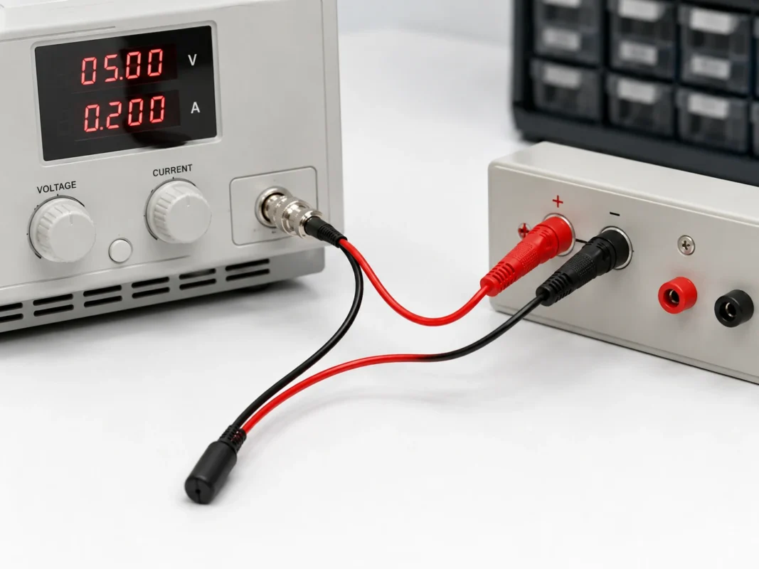
Two products may both be advertised as a BNC to banana adapter while having completely different mechanical structures.
The first is a rigid adapter. It normally has a BNC connector on one end and two fixed banana plugs on the other. The banana contacts are held at a defined center-to-center spacing so the complete adapter can be inserted directly into a matching pair of binding posts.
The second is a flexible BNC to banana plug cable. It uses a BNC connector, a length of coaxial or paired cable and two separated leads terminated with individual red and black banana plugs.
Neither structure is universally better. The correct choice depends on the front-panel layout, the distance between the equipment and the test point, and how frequently the connection must be moved.
Identify the rigid dual-banana adapter
A rigid BNC-to-dual-banana adapter is useful when the destination equipment has two binding posts arranged at the same pitch as the adapter.
Its main advantages are compactness and fast installation. There is no loose breakout section to route across the bench, and the short signal path reduces clutter. It may be suitable for training instruments, audio test equipment, passive circuit boxes and laboratory terminal panels.
The limitation is that both banana contacts are locked into one body. They cannot be moved independently. Even when both sides use nominal 4 mm sockets, the adapter may not fit if the binding-post spacing is different, the sockets are recessed, or a neighboring control blocks the BNC body.
A rigid adapter can also place mechanical leverage on the equipment panel. A heavy BNC cable hanging from the opposite side may twist the banana sockets or place stress on their internal mounting hardware.
Identify the flexible banana plug cable
A flexible BNC to banana cable separates the two banana plugs, allowing each plug to reach an independently positioned terminal.
This version is usually more practical when:
- The binding posts are farther apart than a fixed dual plug.
- The terminals are arranged vertically rather than horizontally.
- One socket is recessed or located behind a panel edge.
- The BNC instrument sits away from the terminal panel.
- Nearby switches or knobs prevent the use of a rigid body.
- Repeated repositioning is part of the test procedure.
The flexible structure also reduces direct mechanical leverage on the binding posts. However, the exposed loop formed by the separated conductors is usually larger and more variable. This matters when the signal contains fast edges or higher-frequency components.
Treat the search direction as an interface description
Search phrases such as banana plug to BNC adapter, BNC banana plug adapter and BNC to banana adapter usually describe the same interface combination. They do not necessarily indicate that the signal can travel in only one direction.
A passive adapter normally has no directional circuitry. The important questions are:
- Is the BNC connector male or female?
- Is it designed for 50 Ω or 75 Ω equipment?
- Are the banana contacts fixed or separated?
- Are they standard 4 mm plugs?
- Which plug connects to the BNC center contact?
- Which plug connects to the BNC shell?
- What voltage and current can the complete assembly handle?
- Does its mechanical arrangement fit the intended instrument?
Product direction should therefore be described through connector gender and wiring, not merely through the order of words in the product title.
Map the BNC Center and Shell to the Banana Plugs
A typical BNC connector contains two conductive paths. The center contact carries the primary signal, and the outer shell connects to the coaxial shield or reference conductor.
A common BNC-to-banana wiring arrangement is:
This mapping is logical and widely used, but it should never be assumed from plug color alone.
Assign the center conductor to the signal plug
In many assemblies, the BNC center contact is connected to the red banana plug. The red plug is then treated as signal, positive or high, depending on the application.
These words are not always interchangeable. In an AC waveform test, “signal” is usually more accurate than “positive.” The instantaneous voltage may move above and below the reference level. In other systems, the red lead may carry a sensor output, trigger pulse or control voltage.
Use the terminology shown on the equipment schematic rather than assuming every red terminal is a DC-positive connection.
Assign the BNC shell to the reference plug
The BNC outer shell is commonly wired to the black banana plug. The black plug may be identified as return, common, reference, shield or ground.
Those labels can describe electrically different conditions.
A return conductor carries current back toward the source. A circuit common is a reference node shared by parts of a circuit. Protective earth is a safety connection associated with the equipment chassis and building ground. A shield may be connected to earth at one point, at both ends or through another network.
Therefore, a black banana plug should not automatically be connected to any node marked “ground” until the instrument grounding arrangement has been checked.
Verify the wiring instead of trusting plug color
A digital multimeter can confirm the wiring before the adapter is connected to valuable equipment.
| BNC element | Expected banana connection | Test method | Acceptance |
| Center contact | Red or designated signal plug | Continuity test | Continuous |
| Outer shell | Black or designated reference plug | Continuity test | Continuous |
| Center to shell | No direct connection | Resistance test | Meets project limit |
| Plug color | Matches drawing or label | Visual inspection | Correct |
| Cable movement | No intermittent contact | Dynamic continuity test | Stable |
Place one meter probe on the BNC center contact and the other on the expected signal plug. Repeat the process between the BNC shell and the reference plug.
Next, check resistance between the center contact and shell. A passive two-conductor adapter should not contain an unintended short between them. During a dynamic test, gently move the cable entry, split point and banana plug terminations while watching the meter. Any unstable reading suggests a conductor, solder joint, crimp or strain-relief problem.
Will a Fixed Dual-Banana Adapter Fit the Binding Posts?
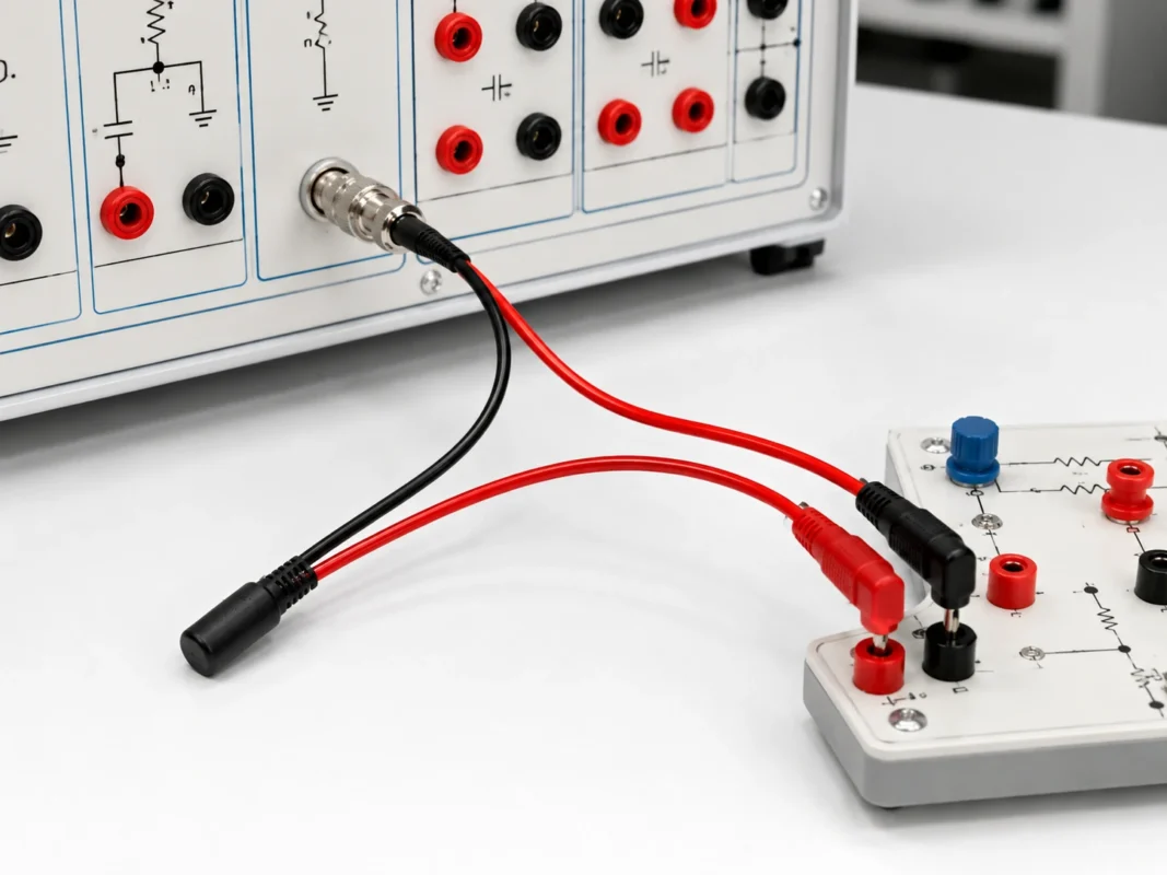
The phrase “4 mm banana plug” identifies the approximate contact diameter, but it does not guarantee that a fixed dual-plug adapter will fit a particular instrument.
You must also check the center-to-center distance between the binding posts.
The acceptable tolerance must come from the actual product dimensions, plug flexibility, socket structure and equipment drawing. A universal tolerance should not be assumed.
Measure the center-to-center post spacing
Measure from the center of one socket to the center of the other rather than from the outside edge of the binding-post bodies.
Also record:
- Socket diameter
- Usable insertion depth
- Panel recess depth
- Distance to adjacent controls
- Orientation of the terminal pair
- Space required by the BNC coupling sleeve
A product may appear to match the spacing but still fail to seat fully because the adapter housing contacts the front panel before the plugs reach the bottom of the sockets.
Check horizontal, vertical and recessed arrangements
Some laboratory equipment uses horizontal red and black binding posts. Others place the terminals vertically. Certain educational panels use deeply recessed safety sockets, while older equipment may have exposed metal binding posts.
A rigid adapter designed for a horizontal pair may technically enter a vertical pair, but the attached cable may hang awkwardly or obstruct the display. On crowded equipment, the BNC body can also block a power switch, adjustment knob or neighboring terminal.
Mechanical compatibility should be evaluated as part of the connection system, not as a separate cosmetic issue.
Use a flexible cable when the pitch does not match
Choose a flexible BNC-to-banana test lead when the sockets do not match a fixed pitch or when the equipment layout creates excessive leverage.
Separate leads are also preferable when one banana connection must reach a signal terminal and the other must reach a remote common point. The individual conductors can be routed naturally without forcing the equipment sockets toward each other.
Do not bend the contacts of a rigid dual-banana adapter to compensate for incorrect spacing. Permanent bending can reduce contact pressure, damage the insulation or transfer stress into the internal wiring.
Does the Connection Stay at 50 Ohms After the Breakout?
A BNC connector and its coaxial cable section may be designed for a nominal 50 Ω system. This does not mean that the entire BNC-to-banana assembly remains a controlled 50 Ω transmission line.
The coaxial section controls impedance through a defined relationship between the center conductor, dielectric and surrounding outer conductor. At the banana breakout, the shield no longer completely surrounds the signal conductor. The two conductors become separate wires or terminals with variable spacing.
This transition changes the electrical geometry.
Separate the coaxial section from the banana section
Before the breakout, the BNC connector and cable may provide:
- Controlled characteristic impedance
- Continuous shielding
- Defined conductor spacing
- Lower radiation and pickup
- More repeatable high-frequency behavior
After the breakout, the connection may have:
- Variable signal-to-return spacing
- A larger current-loop area
- More exposure to external electric and magnetic fields
- Additional parasitic inductance
- Additional parasitic capacitance
- Greater sensitivity to lead placement
TEJTE’s 50-ohm BNC cable guide explains why impedance consistency must be considered from the source through the cable, connectors and termination. A BNC-to-banana adapter represents the point where that controlled coaxial chain enters an open terminal system.
Use the adapter for low-frequency and functional work
A BNC-to-banana adapter is commonly more appropriate for:
- DC measurements
- Audio-frequency testing
- Low-frequency function-generator signals
- Basic filter and amplifier demonstrations
- Educational circuit experiments
- Low-speed control signals
- Sensor simulation
- Continuity and functional verification
These applications are generally less sensitive to the uncontrolled geometry of the separated banana conductors.
Even at low frequencies, the voltage, current and grounding conditions must still be checked. “Low frequency” does not automatically mean “low risk.”
Avoid treating it as a precision GHz adapter
The BNC connector may have an RF frequency rating, but the complete BNC-to-banana assembly should not be assigned the same bandwidth without measurement.
Usable performance depends on:
- Length of the exposed leads
- Distance between signal and return
- Source impedance
- Load impedance
- Signal rise and fall times
- Required amplitude accuracy
- Permitted overshoot and ringing
- External electromagnetic noise
- Contact condition
- Test-fixture geometry
A square wave can contain significant high-frequency energy even when its repetition rate appears low. Fast edges may produce ringing or overshoot through a breakout lead that performs acceptably with a sine wave at the same fundamental frequency.
When controlled impedance is essential, maintain a coaxial interface and use an appropriate load, fixture or feed-through connection. TEJTE’s BNC coupler guide can help when the actual task is to extend or pass a coaxial BNC connection without converting it to binding posts.
Where Can You Use This Adapter Safely?
The adapter is most useful when the equipment on one side provides a BNC signal port and the other side provides compatible banana sockets or binding posts.
Safe use depends on understanding the circuit behind both interfaces.
Connect a function generator to binding-post inputs
A function generator may be connected to a low-voltage circuit board, passive network or teaching panel through a BNC-to-banana cable.
Before connecting, verify:
- Generator output amplitude
- DC offset
- Generator output impedance
- Expected load impedance
- Maximum input voltage of the circuit
- Reference-terminal potential
- Whether the generator shell is earth-referenced
Many generators specify amplitude based on a particular load condition. The displayed voltage may not equal the actual open-circuit voltage. Review the equipment manual and measure the output when necessary.
Never connect a generator output directly to another active output unless the equipment is specifically designed for that arrangement.
Connect BNC instruments to laboratory terminal panels
The adapter can simplify connections to:
- Laboratory patch panels
- Custom test fixtures
- Training boards
- Passive component boxes
- Terminal strips
- Low-voltage development systems
- Electronic load signal or sense terminals
- Instrumentation input panels
For repeated production testing, label both banana plugs and mechanically support the cable. A documented connection procedure reduces reversed polarity and prevents operators from using the same lead in an unsuitable high-voltage test.
Use caution with oscilloscope inputs
On many bench oscilloscopes, the BNC shell is connected to the instrument chassis and protective earth. Connecting the corresponding black banana plug to a circuit node may therefore force that node to earth potential.
This can create a short circuit, damage the device under test, trip protection equipment or expose the operator to a hazardous condition.
Before using an ordinary grounded oscilloscope:
- Identify the circuit reference node.
- Check whether that node may be connected to protective earth.
- Confirm the oscilloscope input rating.
- Verify whether the BNC shells of multiple channels share a common connection.
- Use a suitable differential or isolated measurement system when the node is floating or at high common-mode voltage.
Do not defeat the oscilloscope protective-earth connection to make the instrument “float.”
Reject unknown high-voltage applications
A general BNC banana plug adapter should not be assumed suitable for:
- AC mains circuits
- Offline switch-mode power supplies
- Inverter outputs
- Motor drives
- High-voltage battery stacks
- Floating high-side measurements
- High-energy capacitor systems
- Unknown current paths
These applications require measurement accessories with defined insulation, working-voltage, transient, category, creepage and clearance ratings.
The IEC 61010 family addresses safety requirements for electrical equipment used in measurement, control and laboratory environments. Use equipment and accessories whose published ratings match the actual measurement task rather than relying on connector appearance alone.
Choose Between a Rigid Adapter and a Flexible Cable
The choice should be made according to the equipment layout and test process rather than price alone.
| Requirement | Rigid adapter | Flexible cable |
| Matching paired binding posts | Preferred | Compatible |
| Irregular terminal spacing | Poor fit | Preferred |
| Compact bench arrangement | Preferred | Depends on routing |
| Reduced socket leverage | Moderate | Better |
| Minimum loose wiring | Better | Lower |
| Independent terminal access | Not possible | Preferred |
| Frequent repositioning | Less convenient | Preferred |
| High-frequency repeatability | Must be validated | Usually more variable |
Pick a rigid body for compact fixed terminals
A rigid adapter works well when the binding posts have the correct spacing and the connection will remain in place.
It keeps the bench tidy and reduces loose lead length. It can also make polarity easy to identify when the adapter body clearly marks the signal and reference contacts.
Check that the attached BNC cable does not hang vertically from the adapter or act as a lever. Where necessary, support the cable or use a short flexible jumper.
Pick a flexible cable for irregular layouts
A flexible BNC-to-banana plug cable offers better routing and lower mechanical stress when the destination terminals are separated.
It is also easier to use with equipment that has deep panels, angled front surfaces or unrelated terminal positions.
Keep the signal and return leads close together where practical. Avoid creating a large loop across the bench, especially when testing low-level signals or waveforms with fast transitions.
Consider handling frequency
For a connection that remains installed for weeks, a rigid adapter may provide a cleaner setup. For daily experiments, classroom use or repair work, flexible leads usually adapt to more situations.
Repeated bending should occur in the cable rather than directly at the connector termination. Molded strain relief or a suitable flexible boot can improve durability.
How Do You Control Voltage, Current and Grounding Risk?
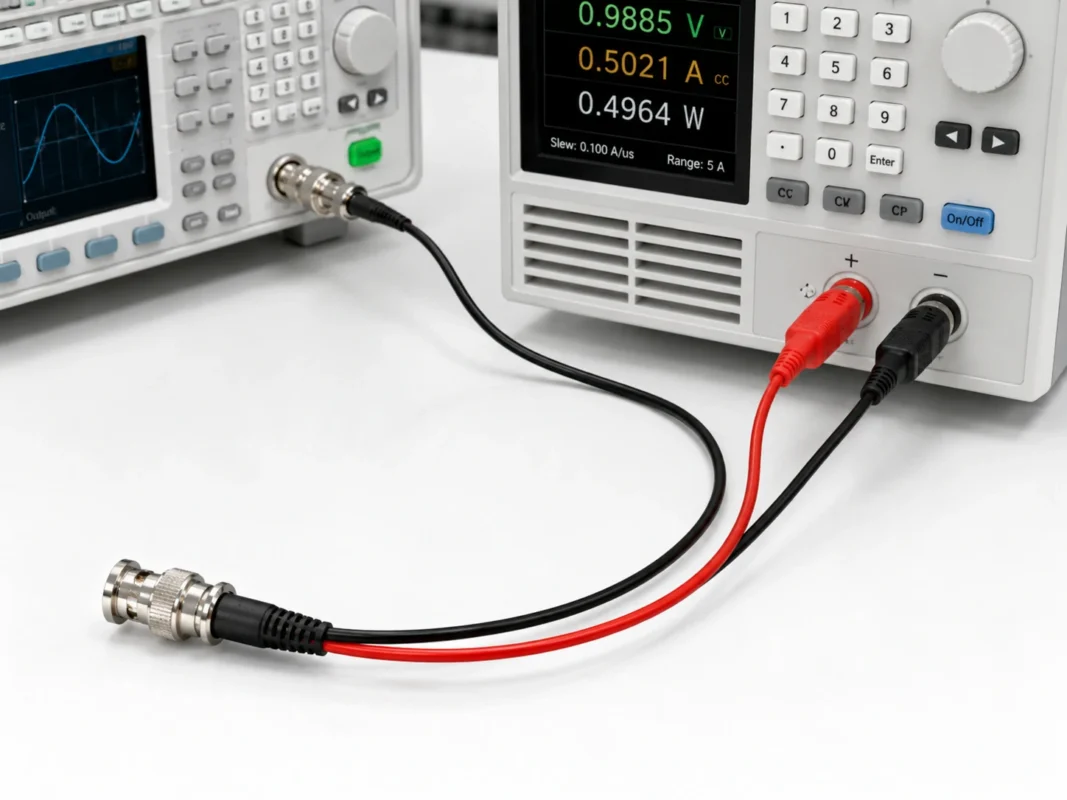
Voltage and current are separate ratings. A product that tolerates a certain voltage may not safely carry a high current, and a plug that carries substantial current at low voltage may not have enough insulation for a higher-voltage application.
Confirm the complete assembly ratings
Request or verify:
- Maximum working voltage
- Maximum current
- Conductor cross-section
- Contact resistance
- Insulation resistance
- Dielectric withstand rating
- Plug-contact material
- Connector-body insulation
- Temperature range
- Temperature rise under load
- Applicable safety category, when relevant
The lowest-rated part determines the usable rating of the complete assembly. This includes the BNC interface, wire, split junction, solder or crimp termination, insulation and banana plugs.
Identify whether the BNC shell is grounded
Use several sources of evidence:
- Instrument operating manual
- Input or output schematic
- Shell-to-chassis continuity measurement
- Chassis-to-protective-earth continuity measurement
- Front-panel isolation marking
- Manufacturer statement for isolated channels
Do not rely entirely on a single continuity reading when the equipment is powered off. Some instruments use switching, relays, protection networks or frequency-dependent coupling.
Prevent accidental shorts between instruments
A ground loop or short can occur when two earth-referenced instruments are connected to different points in a circuit.
For example, the black banana plug from a function generator and the black banana plug from an oscilloscope may both connect through their BNC shells to protective earth. Attaching them to two different circuit nodes can short those nodes together through the instruments.
Use this safety gate before connection:
Verify Samples Before Bulk Purchase
A product photograph is not enough to approve a BNC banana plug adapter for repeated laboratory or production use.
Sample inspection should cover the mechanical interface, internal wiring and behavior during movement.
Inspect the mechanical interface
Check:
- BNC male or female configuration
- Bayonet sleeve movement
- Center-contact alignment
- 50 Ω or 75 Ω specification
- Banana-plug diameter
- Fixed plug spacing
- Spring-contact pressure
- Cable-entry support
- Split-junction molding
- Insulation condition
- Product markings
BNC connectors use a quick bayonet coupling and are available in both 50 Ω and 75 Ω configurations. The impedance should therefore be stated on the drawing or specification rather than judged from the external appearance.
Test continuity while moving the leads
Connect a multimeter and gently move the assembly at the following locations:
- BNC cable entry
- Adapter body
- Main cable
- Wire split point
- Banana-plug entry
- Strain-relief sleeve
The resistance should remain stable. An intermittent reading may reveal an incomplete crimp, damaged conductor, weak solder joint or insufficient strain relief.
Do not perform an aggressive pull test unless a force and method have been defined. An uncontrolled manual pull can damage a good sample without producing useful comparative data.
Compare measurements against a reference connection
For functional approval:
- Apply a known low-voltage signal.
- Measure it through a suitable reference connection.
- Replace the reference with the BNC-to-banana assembly.
- Compare measured amplitude.
- Compare noise and waveform shape.
- Reposition the banana leads.
- Repeat the test.
- Record any variation.
For higher-frequency work, the comparison should include rise time, overshoot, ringing and sensitivity to lead position. If repeatability is unacceptable, retain a coaxial connection or redesign the fixture.
Incoming inspection standard
| Inspection item | Method | Acceptance record |
| BNC gender | Drawing and visual check | Correct/incorrect |
| BNC impedance | Specification review | 50 Ω/75 Ω |
| Banana diameter | Dimensional measurement | Target ± tolerance |
| Fixed plug spacing | Dimensional measurement | Target ± tolerance |
| Center-to-signal continuity | DMM | Pass/fail |
| Shell-to-reference continuity | DMM | Pass/fail |
| Center-to-shell isolation | Resistance test | Project limit |
| Dynamic continuity | Flex test | Stable/unstable |
| Plug retention | Insertion and removal test | Pass/fail |
| Final decision | Combined review | Approve/reject |
What Information Belongs on the RFQ?
A clear RFQ prevents the supplier from choosing the interface arrangement from a product title or reference photograph.
Name the exact BNC interface
Specify:
- BNC male or BNC female
- 50 Ω or 75 Ω
- Straight or angled orientation
- Standard or insulated body
- Contact and shell finish
- Required mating connector
A request that says only “BNC male to banana plug” does not define the banana arrangement, cable length, wiring, ratings or plug spacing.
Define the banana-plug arrangement
Include:
- One or two banana plugs
- 4 mm or another diameter
- Fixed dual-plug body or separate leads
- Fixed contact spacing
- Red and black color assignment
- Stackable or non-stackable plugs
- Shrouded or unshrouded construction
- Required insertion depth
- Desired contact material or finish
Shrouded plugs may not fit older exposed binding posts, while unshrouded plugs may not meet the safety requirements of certain equipment. Confirm the receiving socket design.
Document the wiring
Write the mapping directly:
Where another arrangement is required, provide a drawing. Do not describe a nonstandard wiring scheme only through plug color.
State the operating conditions
The RFQ should contain:
For a long connection that does not actually need banana terminals, review the TEJTE BNC extension cable guide before adding an unnecessary breakout. Maintaining the coaxial path may provide better shielding and more predictable signal behavior.
Which Alternative Lead Solves the Job Better?
A BNC banana adapter is only one of several ways to connect a laboratory instrument to a device under test.
Choose alligator clips for exposed terminals
A BNC-to-alligator lead may be more practical for:
- Bare wires
- Large solder pads
- Ground studs
- Battery tabs
- Temporary circuit points
- Irregular metal terminals
Alligator clips are quick to attach but may slip, rotate or contact adjacent conductors. They are not automatically suitable for high voltage, high current or fast waveform measurements.
Choose banana plugs for standard binding posts
Banana plugs are better suited to equipment with defined banana sockets or binding posts, including:
- Laboratory power supplies
- Electronic loads
- Audio equipment
- Training systems
- Terminal panels
- Passive test boxes
- Low-frequency signal fixtures
They usually provide a cleaner and more repeatable mechanical connection than clips when the correct sockets are available.
Choose a passive or differential probe for waveform measurement
An oscilloscope probe is preferable when the task requires:
- Defined attenuation
- Probe compensation
- Lower input capacitance
- Short ground connection
- Reduced loop area
- Fast-edge measurement
- Better waveform repeatability
For floating or high-common-mode measurements, use a properly rated differential or isolated probe system.
Keep the interface coaxial when RF impedance matters
Do not use banana terminals merely because they are convenient when the test requires:
- VNA measurements
- Insertion-loss testing
- Return-loss testing
- RF module characterization
- Controlled 50 Ω fixtures
- High-frequency signal-integrity analysis
- Repeatable phase measurements
In those cases, continue the BNC or another appropriate coaxial interface and terminate the system correctly. The TEJTE 50-ohm BNC terminator guide explains how the source, transmission path and load work together to control reflections.
Final Selection Checklist
Before ordering or connecting a BNC-to-banana adapter, confirm all of the following:
- Correct BNC gender
- Correct nominal impedance
- Rigid or flexible structure
- Correct banana-plug diameter
- Compatible fixed plug spacing
- Verified center and shell mapping
- Suitable working-voltage rating
- Suitable current rating
- Compatible instrument grounding
- Acceptable signal frequency and edge speed
- Adequate insulation and strain relief
- Sample continuity under movement
- Mechanical fit without socket stress
- Clear RFQ and approved drawing
A BNC-to-banana adapter is a useful laboratory accessory when it is treated as an intentional interface transition rather than a universal RF adapter. The BNC section may begin as a controlled coaxial path, but the banana breakout introduces a different geometry, grounding arrangement and mechanical environment.
Choose a rigid adapter for compatible paired binding posts and a flexible cable for irregular terminal layouts. Verify the wiring with a meter, check whether the BNC shell is earth-referenced, and never assume that connector fit alone proves electrical safety.
When low-frequency access to standard binding posts is the real requirement, the adapter can provide a simple and efficient connection. When impedance control, fast-edge fidelity, floating measurement or high-voltage safety is the priority, use a connection system designed specifically for that task.
FAQ
Does “banana plug to BNC adapter” mean the signal only travels toward the BNC side?
No. The wording generally describes the two interfaces rather than a required direction of signal flow. Compatibility depends on the connector genders, internal wiring, ratings and connected equipment.
Can a fixed dual-banana adapter fit every pair of binding posts?
No. The plug spacing, insertion depth, panel recess and surrounding clearance must match the equipment. Use a flexible cable when the terminal layout is irregular.
Is the red banana plug always connected to the BNC center pin?
It commonly is, but color is not proof of wiring. Confirm the product drawing or perform a continuity test before connecting the adapter.
Can a BNC-to-banana adapter preserve a true 50-ohm path?
The BNC and coaxial portion may be designed for 50 Ω, but the separated banana terminals do not maintain the same controlled coaxial geometry. The difference becomes more important as frequency and signal edge speed increase.
Can I connect a function generator directly to power-supply binding posts?
Only when the terminals are intended to receive an external signal and the voltage, current, grounding and impedance conditions are compatible. Do not connect two active outputs together unless the equipment documentation explicitly permits it.
Why does the waveform change when the banana leads are moved?
Moving the leads changes their spacing, loop area and parasitic inductance and capacitance. A loose or contaminated plug may also create variable contact resistance.
When is a BNC-to-alligator cable better than a BNC-to-banana adapter?
Use alligator clips for temporary connections to exposed conductors, large pads or irregular terminals. Use banana plugs when the equipment provides compatible binding posts or banana sockets.
