
A BNC-to-alligator-clips lead looks simple: one BNC connector, one length of cable, and two clips. On a laboratory bench, however, this assembly changes the electrical behavior of the signal path in an important way.
Inside the BNC connector and coaxial cable, the signal conductor is surrounded by a shield. This geometry helps control impedance, limit electromagnetic pickup, and provide a defined return path. At the breakout end, the center conductor and shield are separated into two individual wires. The cable is no longer fully coaxial at that point.
That transition is the main reason a BNC to alligator clips cable can be convenient for low-frequency troubleshooting but unsuitable for precision RF measurements, fast digital edges, or unsafe floating-node measurements.
This guide explains how to identify the wiring, connect the clips safely, estimate the practical signal limitations, select the correct cable construction, inspect custom assemblies, and prepare an unambiguous purchase specification.
For a broader explanation of BNC impedance, shielding, signal type, and cable length, first review the BNC cable selection guide. This article focuses specifically on what changes after the coaxial structure opens into two clip leads.
Where Does a BNC-to-Clip Lead Fit on the Bench?
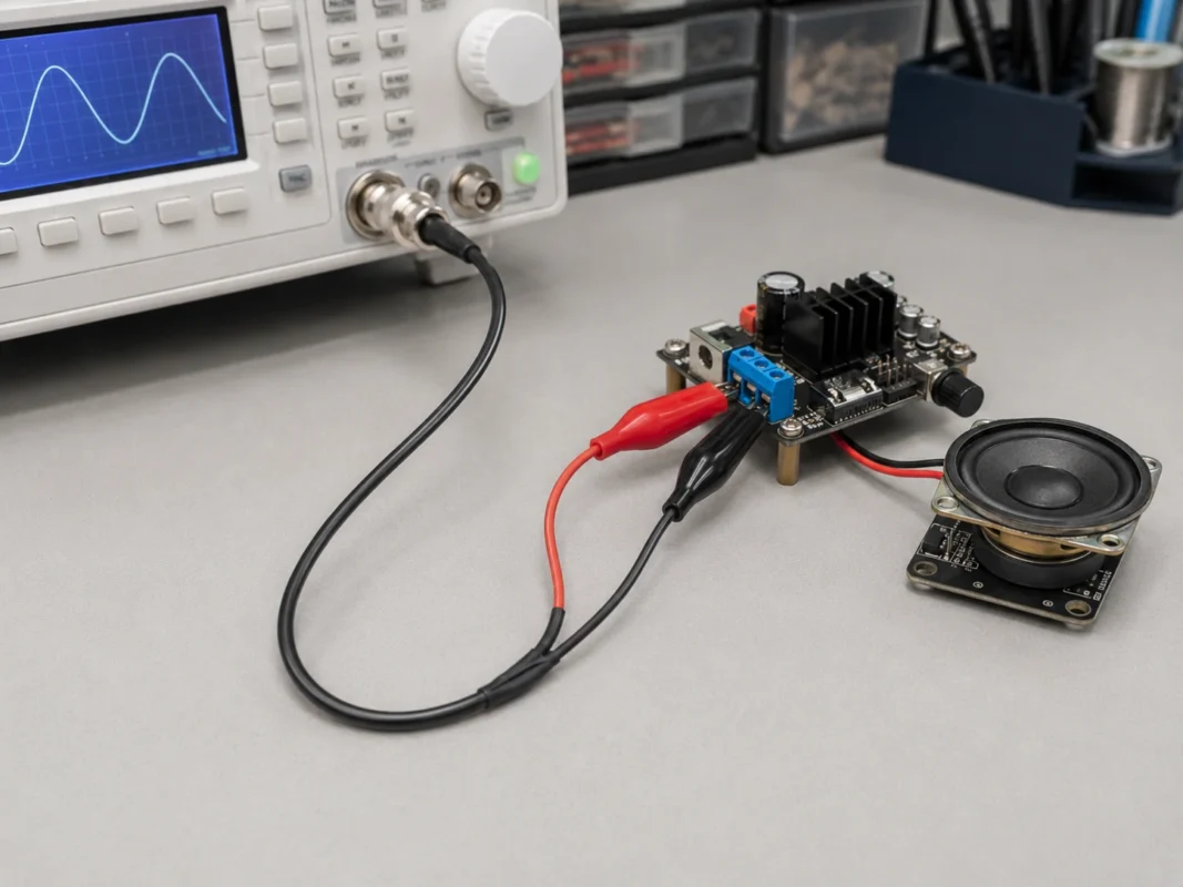
A BNC breakout lead provides temporary access between a BNC-equipped instrument and a circuit that does not have a matching coaxial connector.
Common examples include connecting a function generator to a breadboard, feeding a low-frequency signal into a repair fixture, observing a control waveform with an oscilloscope, or attaching a frequency counter to a large test terminal.
The lead is useful because it removes the need to install a BNC connector on every temporary test point. The clips can attach quickly to screw terminals, ground studs, battery tabs, bus bars, exposed pads, or component leads.
Convenience, however, should not be confused with measurement quality.
Connect BNC instruments to temporary circuit points
Typical bench applications include:
- Function generator output to a development board
- Oscilloscope input to a low-voltage signal point
- Frequency counter input to a temporary test fixture
- Audio generator output to an amplifier input
- Pulse source connection to a relay or control circuit
- Signal injection during equipment repair
- Educational demonstrations using breadboards
- Continuity and functional checks on assembled hardware
For these tasks, the lead offers faster setup than building a permanent coaxial fixture.
A BNC-to-clip cable is especially practical when the connection must be changed repeatedly. A repair technician may need to inject a test signal at several points in a circuit. A hardware developer may move the reference clip between different ground locations. An instructor may need students to connect the same generator to multiple breadboard circuits.
Separate temporary access from precision measurement
A BNC to alligator clip cable is generally appropriate for:
- Low-frequency waveform observation
- Audio signals
- DC and slow control signals
- Basic pulse testing
- Temporary signal injection
- Functional verification
- Educational experiments
- Repair and troubleshooting work
It should not automatically be selected for:
- Calibration-grade measurements
- Controlled-impedance RF testing
- GHz signal characterization
- High-voltage floating nodes
- Mains-referenced switching circuits
- High-current power connections
- Measurements requiring defined probe attenuation
- Sensitive rise-time or overshoot verification
- Situations requiring a specified input capacitance
A standard oscilloscope probe is not merely a wire with a tip. It may include attenuation components, compensation adjustment, controlled input resistance, defined capacitance, shielding, and accessories designed to reduce the ground loop. A basic BNC breakout cable provides none of these characteristics unless they are specifically engineered into the assembly.
Recognize when the product is called a breakout lead
Suppliers may describe the same general product using several names:
- BNC to alligator clips
- BNC to crocodile clips
- BNC breakout cable
- BNC test leads
- BNC cable with alligator clips
- BNC oscilloscope test leads
- BNC male to alligator clips
“Breakout cable” is the broader term. It means the conductors inside a connector or cable are separated into individually accessible terminations.
The breakout end does not have to use alligator clips. It may terminate in:
- Bare wires
- Ferrules
- Banana plugs
- Test hooks
- Mini-grabbers
- Ring terminals
- Spade terminals
- PCB headers
Therefore, a BNC alligator clip cable is one type of BNC breakout cable, not a complete synonym for every breakout configuration.
How Are the BNC Center and Shield Split Into Two Clips?
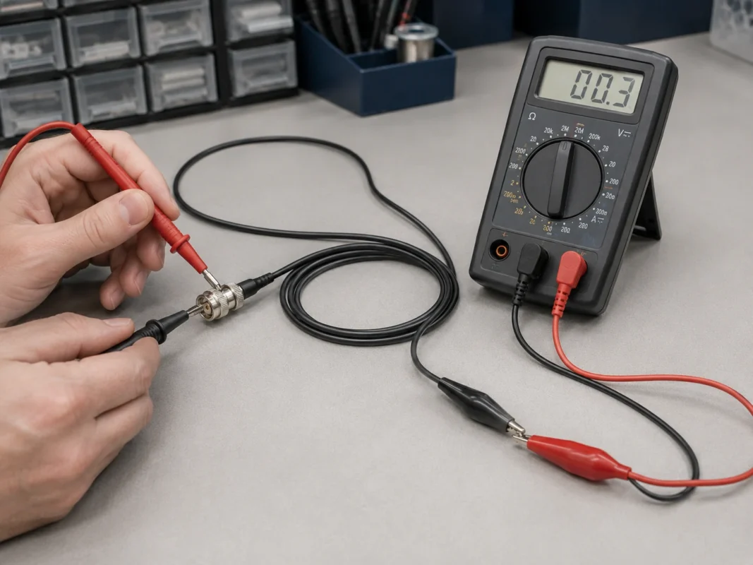
A conventional BNC coaxial assembly contains two main electrical paths:
- The BNC center contact connects to the coaxial cable’s inner conductor.
- The BNC outer shell connects to the coaxial shield.
At the clip end, these two paths are separated.
In many assemblies, the inner conductor is connected to a red clip and the shield is connected to a black clip. This is a common convention, but it is not a universal electrical guarantee.
Color helps the operator recognize the intended connection. It does not prove the internal wiring.
Trace the center conductor to the signal clip
The BNC center contact normally carries the signal. In a typical red-and-black assembly, this conductor runs to the red alligator clip.
The red clip may be described as:
- Signal
- Output
- Input
- Positive
- Hot
- Center conductor
“Positive” should be used carefully. An AC waveform changes polarity, and some circuits use negative-going signals. The technically accurate description is usually “signal clip” or “center-conductor clip.”
Before first use, verify continuity between the BNC center contact and the intended signal clip.
Trace the connector shell to the reference clip
The BNC shell normally connects to the coaxial shield. At the breakout end, the shield is connected to the reference clip, commonly black.
Depending on the instrument and circuit, this clip may represent:
- Signal return
- Circuit common
- Chassis reference
- Protective-earth-connected ground
- Generator return
- Oscilloscope input reference
These terms are not interchangeable.
For example, a circuit’s negative supply terminal is not always connected to earth. A chassis may be grounded while the signal common is isolated. A battery-powered board may float relative to the laboratory bench.
That is why the operator must identify the actual circuit reference before attaching the black clip.
Reject undocumented internal mapping
A product listing that only says “BNC cable with red and black clips” is incomplete.
A technical drawing or product specification should state:
- BNC connector gender
- Nominal cable impedance
- BNC center-contact destination
- BNC shell destination
- Red-clip wiring
- Black-clip wiring
- Center-to-shell isolation
- Cable type
- Overall length
- Split-lead length
The following wiring map can be used for sample approval.
| BNC element | Internal path | Typical termination | Verification method |
| Center contact | Inner conductor | Red signal clip | Continuity test |
| Connector shell | Cable shield | Black reference clip | Continuity test |
| Center to shell | Isolation path | No intentional connection | Resistance test |
| Clip color | Visual identifier | Red and black | Compare with drawing |
| Final mapping | Confirmed electrical route | Pass or fail | Inspection record |
A continuity test is inexpensive and should be performed before an unfamiliar lead is connected to valuable equipment.
Which Clip Should Touch Signal and Which Should Touch Reference?
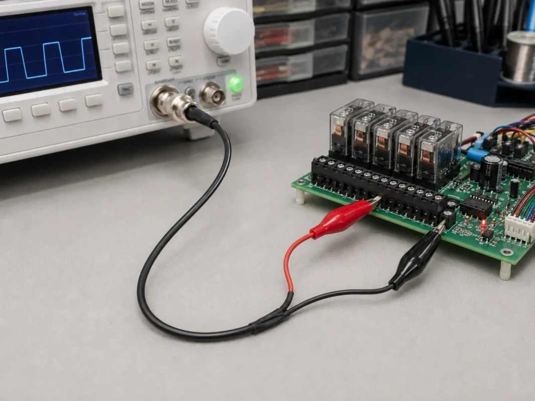
The signal clip normally connects to the circuit node being measured or driven. The reference clip connects to the return or reference point required by the instrument.
The difficult part is not identifying red and black. The difficult part is determining whether the intended reference point is electrically compatible with the instrument’s BNC shell.
Identify the circuit reference first
Before connection, determine which of the following applies:
- Circuit ground
- Signal common
- Power return
- Chassis ground
- Protective earth
- Isolated reference
- Floating reference
- High-side switching node
These points may have different voltages between them.
Consider a battery-powered development board. Its negative terminal may float relative to earth until a grounded oscilloscope is attached. Connecting the oscilloscope reference clip can force that point to earth potential.
This may be harmless in a simple low-voltage circuit. It may be destructive in an inverter, bridge circuit, offline power supply, or system containing multiple grounded instruments.
Connect the reference clip in a controlled sequence
For a compatible low-voltage circuit, a practical connection sequence is:
- Turn off the circuit when practical.
- Confirm the BNC center-to-clip mapping.
- Check whether the instrument BNC shell is earth-referenced.
- Identify the circuit’s intended reference point.
- Attach the reference clip.
- Attach the signal clip.
- Power the circuit or enable the source.
- Complete the measurement.
- Disable the signal or power.
- Remove the signal clip first.
- Remove the reference clip last.
This order reduces the chance that the signal lead will touch an undefined node while the return path is disconnected.
Do not treat black as automatically safe ground
On many traditional bench oscilloscopes, the BNC shell is connected to the chassis and protective earth. This means the black clip may have a direct or low-resistance path to earth ground.
If that clip is attached to a non-earth node, the connection can short the circuit through the oscilloscope.
The risk is not limited to incorrect readings. Possible outcomes include:
- Damaged circuit traces
- Failed switching devices
- Burned probe leads
- Tripped protection devices
- Damaged oscilloscope inputs
- Dangerous touch voltage
- Arc or spark at the connection point
Tektronix explains that conventional grounded oscilloscope probe reference leads should be connected only to an earth-ground-referenced point. Defeating the instrument’s protective-earth connection can place hazardous voltage on accessible metal parts.
Use this decision process before connecting:
- Is the black clip confirmed to connect to the BNC shell?
- Is the instrument shell connected to protective earth?
- Is the intended circuit point at earth potential?
- Are the voltage and current within the assembly’s ratings?
- Is a single-ended measurement appropriate?
When any answer is unknown, stop and verify the system instead of relying on clip color.
Can You Use This Lead on an Oscilloscope Safely?
A BNC-to-alligator lead can be used with an oscilloscope in limited situations, but it should not be treated as a universal replacement for a standard probe.
The first question is not bandwidth. It is grounding.
Check whether the oscilloscope input is earth-referenced
Review the instrument manual and determine:
- Whether the oscilloscope is a grounded bench model
- Whether it is an isolated handheld model
- Whether the BNC shells share a common reference
- Whether channels are isolated from one another
- The maximum input voltage
- The maximum BNC shell voltage
- The input impedance
- Whether a 50-ohm termination is enabled
- Whether special isolated inputs are available
Do not infer isolation from the power source alone. A battery-powered instrument may have isolated inputs, common inputs, or limitations on common-mode voltage.
Likewise, an oscilloscope connected through an isolation transformer is not automatically safe for floating measurements. Removing protective grounding can expose the chassis and connected ports to hazardous voltage.
Never place a grounded reference clip on a live high-side node
Problematic applications include:
- Offline AC/DC power supplies
- Rectified mains circuits
- Motor inverters
- Variable-frequency drives
- Half-bridge and full-bridge circuits
- High-side MOSFET measurements
- Solar inverters
- UPS systems
- Stacked battery packs
- Industrial control circuits with different grounds
In a half-bridge circuit, for example, the switching node rapidly moves between supply rails. Connecting an earth-referenced black clip to that node can create a direct short during part of the switching cycle.
The lead may physically attach, but the measurement architecture is wrong.
Use differential or isolated equipment when necessary
A floating or high-common-mode measurement may require:
- A differential oscilloscope probe
- A galvanically isolated probe
- An isolated-input oscilloscope
- A properly rated high-voltage differential probe
- A current probe
- An isolated signal-conditioning module
The replacement must be selected for the actual differential voltage, common-mode voltage, bandwidth, insulation system, and measurement category.
A BNC breakout cable does not create isolation. Separating the red and black leads physically does not separate them electrically from the instrument.
Match ratings to the complete assembly
Do not use the BNC connector’s standalone voltage or frequency rating as the rating of the finished test lead.
The complete assembly may be limited by:
- Cable insulation
- Split-wire insulation
- Clip spacing
- Exposed jaw length
- Clip material
- Crimp construction
- Strain relief
- Connector termination
- Environmental contamination
- Operator access
A metal alligator clip with a partially insulated boot may expose much more conductive area than a protected oscilloscope probe tip.
For purchasing and safety approval, specify the maximum working voltage and current of the assembled cable, not only the connector.
How Much Bandwidth Remains After the Coax Opens Into Two Leads?
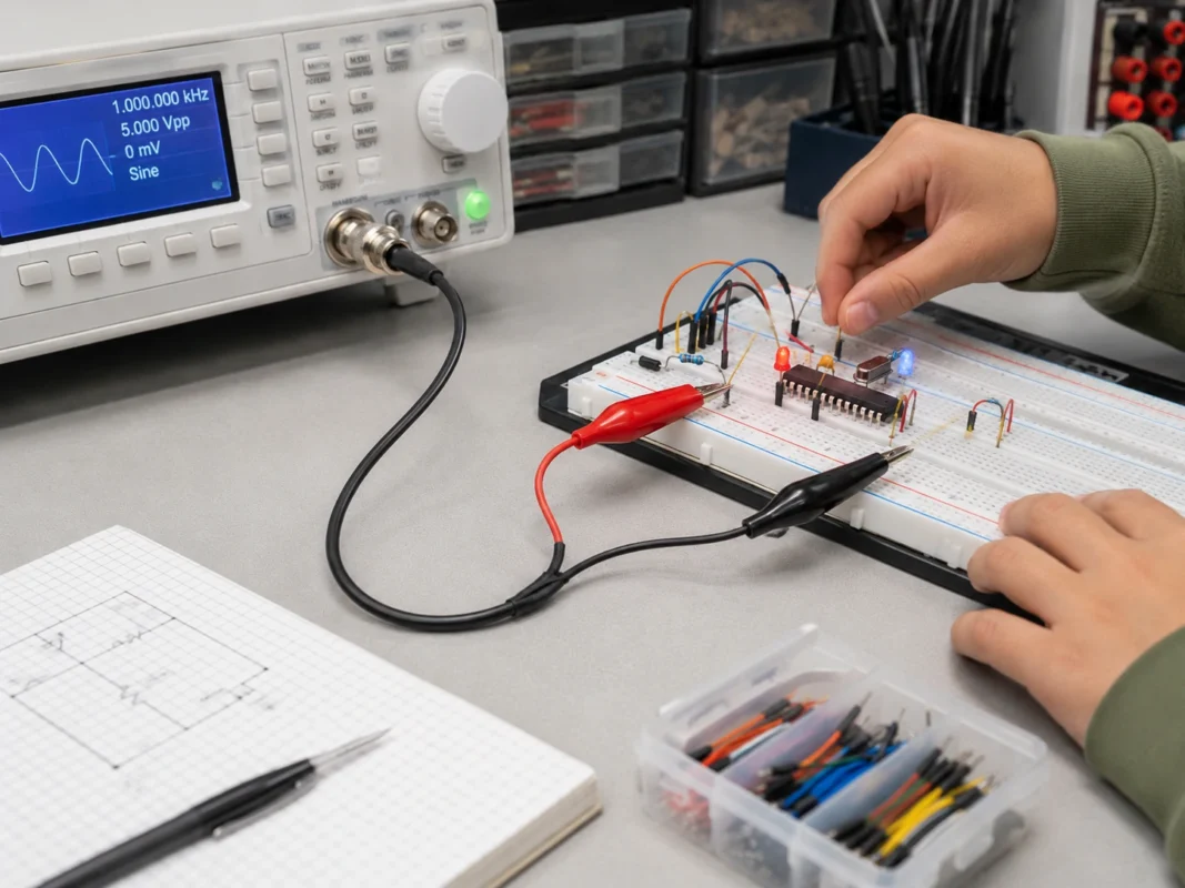
The coaxial section may have a nominal impedance of 50 ohms, but the exposed clip section is no longer a controlled 50-ohm transmission line.
This does not mean the cable stops working. It means its high-frequency behavior becomes less predictable.
Treat the split section as a non-coaxial transition
Inside coaxial cable, the shield surrounds the center conductor. This arrangement creates a defined relationship among conductor diameter, shield diameter, dielectric material, and impedance.
At the breakout:
- The conductors are separated.
- The electromagnetic field is no longer confined in the same geometry.
- Loop area increases.
- Parasitic inductance increases.
- Noise pickup increases.
- Radiation may increase.
- Impedance varies with lead position.
- Results may change when the clips are moved.
The 50-ohm label remains meaningful for the coaxial section. It does not guarantee a 50-ohm condition between the split point and the clips.
Readers who need an end-to-end controlled path should review how to maintain a controlled 50-ohm BNC path and avoid breaking the line into long, separated conductors.
Keep the exposed loop short
A signal travels out through one conductor and returns through another. The physical area between those paths forms a loop.
A large loop generally has more inductance and captures more electromagnetic interference than a small loop.
To reduce the loop:
- Keep the split leads short.
- Place the clips close together.
- Attach the reference clip near the signal point.
- Avoid stretching the two leads in opposite directions.
- Do not route the loop beside transformers or switching inductors.
- Avoid placing it over high-current power traces.
- Do not coil excess split wire.
- Keep the coaxial section intact as close to the DUT as possible.
Rohde & Schwarz notes that long oscilloscope ground leads increase inductance and can produce ringing, overshoot, and undershoot when measuring fast edges. The same principle applies to the separated reference lead of a BNC alligator clip cable.
Define usable bandwidth by waveform accuracy
There is no single honest bandwidth value for every BNC to alligator clips cable.
The practical limit depends on:
- Coaxial cable type
- Overall cable length
- Split-lead length
- Distance between clips
- Source impedance
- Load impedance
- Oscilloscope input mode
- Signal rise time
- Signal amplitude
- Required amplitude accuracy
- Acceptable ringing
- Nearby noise sources
- Clip contact resistance
- Test-point geometry
A slow sine wave may look acceptable while a square wave at the same repetition frequency shows significant ringing. Square-wave edges contain higher-frequency energy than the fundamental frequency alone suggests.
A cable may therefore appear suitable at “1 MHz” when testing a sine wave but distort a 1 MHz digital clock with fast edges.
Use a measurement-risk score
The following score is a practical engineering screen, not an industry standard.
Rate each factor from 1 to 5:
| Total score | Recommended action |
| 6–10 | Suitable for basic low-frequency checks |
| 11–18 | Compare results with a proper probe |
| 19–30 | Use a dedicated probe or coaxial fixture |
For example, a short lead connected to an audio amplifier input in a quiet laboratory may score 7 or 8. A long separated lead attached to a switching converter may score above 20.
The score does not replace a safety review. Any mains-related, floating, or high-voltage condition should be rejected before signal-quality scoring begins.
Choose hooks or probe tips for dense circuit boards
Mini-hooks, grabbers, and standard probes are better for:
- IC pins
- Small vias
- Fine component leads
- Dense PCBs
- Closely spaced test points
- Hands-free measurements on small nodes
A hook can reduce the chance of the contact sliding onto a neighboring pin. A probe tip also allows the reference connection to be placed closer to the signal point.
Choose banana leads for binding posts
Banana plugs are typically more appropriate for:
- Bench power supplies
- Electronic loads
- Digital multimeters
- Binding-post fixtures
- Low-frequency power connections
A banana lead provides better mechanical compatibility with a binding post than an alligator clip attached to the outside of the post.
For higher current, use a cable designed for the required conductor size, insulation temperature, contact resistance, and current rating. A thin RF breakout cable is not a power lead.
Choose a coaxial fixture when impedance matters
Use a fully coaxial connection when testing:
- RF filters
- Amplifiers
- Oscillators
- Matching networks
- Antenna circuits
- Fast clock paths
- Pulse systems
- Controlled-impedance PCBs
Possible interfaces include:
- BNC test fixture
- SMA test fixture
- PCB edge-launch connector
- Short coaxial pigtail
- Probe socket
- Defined 50-ohm load
- Permanently installed test connector
When an instrument input requires termination, use the correct load rather than assuming the clips provide it. The TEJTE guide explains how to terminate a BNC instrument input correctly.
If a fully coaxial cable only needs additional reach, a coupler and another matched cable may be more appropriate than converting the path to clips. Review how to extend a coaxial BNC path without breaking out to clips.
How Should You Choose Cable Length, Clip Size, and Lead Spacing?
Mechanical details often decide whether the cable is practical in daily use.
A technically correct assembly may still fail if the cable pulls on the DUT, the jaws do not open far enough, or the split leads cannot reach both test points.
Choose the shortest practical overall length
Longer cable adds:
- Attenuation
- Capacitance
- Bench clutter
- Mechanical load
- More opportunities for damage
- Greater pickup
- Storage difficulty
An assembly should be long enough to reach naturally without pulling the instrument or DUT.
Use the following worksheet:
| Field | Example unit |
| Instrument-to-DUT route | mm |
| Handling allowance | mm |
| Strain-relief allowance | mm |
| Coaxial section length | mm |
| Split-lead section length | mm |
| Final overall length | mm |
| Length tolerance | ±mm |
Do not add a large safety margin without considering signal performance. Excess length is not free.
Specify the split length separately
“Cable length: 1 meter” does not tell the manufacturer how the final meter is divided.
The drawing should define:
- BNC rear reference point
- Start of breakout
- Coaxial section length
- Red lead length
- Black lead length
- Clip body length
- Overall end-to-end length
- Measurement method
- Length tolerance
Two 1-meter products may behave differently if one has a 50 mm split and the other has a 300 mm split.
For better high-frequency behavior, keep the split section only as long as required to reach the two test points.
Match the jaw opening to the test point
Specify:
- Maximum jaw opening
- Jaw length
- Jaw width
- Tooth profile
- Spring force
- Insulated or exposed jaws
- Clip material
- Contact plating
- Replaceable or fixed clip
- Boot material
- Boot color
A small clip is easier to use on a PCB but may not grip a ground stud. A large clip may grip firmly but can short adjacent terminals.
Evaluate contact material and grip
Common clip constructions include plated steel, copper, and copper-alloy components.
The most suitable choice depends on:
- Required current
- Contact resistance
- Corrosion resistance
- Spring life
- Mechanical strength
- Cost
- Environmental conditions
The cable supplier should not claim “copper clip” unless it is clear whether this means the full clip body, contact insert, jaw surface, or plating.
For repeated production orders, request material descriptions and sample inspection criteria.
How Do You Verify Polarity, Continuity, and Contact Stability?
Every unfamiliar BNC test lead should be checked before use. Custom production samples require a more formal inspection.
Map both conductors with a multimeter
Perform these checks:
- BNC center contact to red clip
- BNC center contact to black clip
- BNC shell to black clip
- BNC shell to red clip
- BNC center to shell
- Red clip to black clip
For the common wiring arrangement:
- Center to red should show continuity.
- Shell to black should show continuity.
- Center to black should remain open.
- Shell to red should remain open.
- Center to shell should remain isolated.
Select a resistance limit appropriate to the project and test equipment.
Flex the cable during continuity testing
A static continuity check may miss an intermittent termination.
Gently flex the assembly at:
- BNC cable entry
- Connector strain relief
- Breakout junction
- Red-lead exit
- Black-lead exit
- Clip crimp
- Clip hinge
- Insulation boot
The reading should remain stable. Any intermittent open circuit, sudden resistance change, or noise indicates a termination problem.
Compare it with a known-good probe
This does not convert the breakout lead into a calibrated probe. It shows whether it is adequate for the intended task.
A strong position-dependent change is evidence that the open-lead geometry is affecting the measurement.
Use an incoming inspection standard
| Inspection item | Method | Acceptance field |
| BNC gender | Visual and drawing | Correct/incorrect |
| Nominal impedance | Specification review | 50Ω, 75Ω, or project value |
| Center-to-signal clip | Continuity | Pass/fail |
| Shell-to-reference clip | Continuity | Pass/fail |
| Center-to-shell isolation | Resistance test | Project limit |
| Clip grip | Mechanical check | Pass/fail |
| Cable flex stability | Dynamic continuity | Stable/unstable |
| Color mapping | Drawing comparison | Correct/incorrect |
| Overall length | Measurement | Target ± tolerance |
| Split length | Measurement | Target ± tolerance |
| Insulation | Visual inspection | Accept/reject |
| Final disposition | Combined review | Accept/reject |
For repeat orders, retain an approved sample and signed drawing so that later shipments are compared against the same standard.
What Must a Buyer Put on the RFQ?
The phrase “BNC to alligator clips” is not enough for a purchase order.
An RFQ should define the connector, cable, wiring, dimensions, ratings, test requirements, and intended application.
State the BNC interface clearly
Use a format such as:
Do not rely on shorthand such as “BNC-J” or “BNC-K” unless both buyer and manufacturer use the same naming convention.
For international RFQs, write:
- BNC male or BNC female
- 50 ohms or 75 ohms
- Straight or right-angle
- Plug or jack, where required
- Cable-mount construction
Define the electrical ratings independently
Specify:
- Maximum working voltage
- Maximum test current
- Intended signal frequency
- Expected rise time, when relevant
- Nominal cable impedance
- Insulation resistance
- Conductor continuity limit
- Shield continuity requirement
- Test environment
Do not state that the complete cable supports the connector’s maximum frequency unless the assembled product has been tested under a defined fixture and acceptance criterion.
The exposed clip section normally prevents the complete assembly from behaving like a controlled RF cable at its maximum connector frequency.
Document cable and clip construction
Include:
- Coaxial cable model
- Cable impedance
- Cable outer diameter
- Jacket material
- Jacket color
- Overall length
- Coaxial section length
- Split-lead length
- Split-wire gauge
- Red and black insulation
- Clip material
- Jaw opening
- Clip body size
- Strain-relief method
- Breakout protection method
For custom coax selection, the BNC coaxial cable structure and selection guide provides useful background on conductor, dielectric, shield, jacket, and termination choices.
Request reports according to project risk
Possible documentation includes:
- Mechanical drawing
- Electrical wiring diagram
- Continuity report
- Isolation test report
- Working-voltage test report
- First-article inspection report
- Material declaration
- Sample approval record
- Packaging specification
- Cable identification label
A low-voltage educational cable may only need continuity inspection. A production test fixture used every day may require flex testing, dimensional inspection, and retained first-article records.
FAQ
Is the black alligator clip always isolated from earth ground?
No. On many bench instruments, the BNC shell is connected to the chassis and protective earth. Check the instrument manual and confirm continuity before attaching the black clip to a circuit.
Why does a square wave show more ringing with alligator clips?
The separated leads create a larger current loop and additional parasitic inductance. Fast waveform edges interact with that inductance and with circuit capacitance, producing overshoot or ringing. Shorten the split leads and place the reference clip close to the signal point.
Can this cable replace a standard 10× oscilloscope probe?
Usually not. A 10× probe provides defined attenuation, compensation, input resistance, input capacitance, shielding, and accessories for reducing the reference loop. A basic BNC breakout lead normally has none of these defined characteristics.
Is a 50-ohm BNC cable still 50 ohms at the clip end?
The coaxial section may have a nominal impedance of 50 ohms. Once the center conductor and shield separate into two clip wires, that section is no longer a controlled coaxial transmission line.
What should be tested when approving custom samples?
Verify BNC gender, center-to-signal continuity, shell-to-reference continuity, center-to-shell isolation, cable length, split length, jaw opening, clip grip, insulation condition, color mapping, and continuity stability while flexing the cable.
Final Selection Principle
A BNC to alligator clips lead is most useful as a temporary low-frequency access tool. It connects BNC instruments to terminals and test points that do not justify a permanent coaxial interface.
Its limitations begin where the coaxial structure ends.
The exposed clip leads create a larger loop, less predictable impedance, more noise pickup, and greater sensitivity to physical placement. More importantly, the reference clip may be electrically connected to the instrument chassis and protective earth.
Select the cable only after answering five questions:
- Which clip connects to the BNC center?
- Which clip connects to the BNC shell?
- Is the shell earth-referenced through the instrument?
- Does the signal require controlled high-frequency behavior?
- Are the full assembly’s voltage, current, insulation, and mechanical ratings documented?
For low-voltage functional checks, education, audio work, temporary signal injection, and large terminal connections, a correctly specified BNC alligator clip cable can be fast and practical.
For floating nodes, mains circuits, fast edges, precision measurements, or controlled RF paths, use a differential probe, isolated measurement solution, standard oscilloscope probe, or fully coaxial fixture instead.
