
A technician adds a BNC tee to an oscilloscope input, connects two 50-ohm instruments, and sees the waveform amplitude drop. Nothing is broken. Every connector mates correctly, and continuity checks pass.
The problem is electrical.
A basic BNC T connector does not automatically divide a signal into two matched outputs. In most cases, it simply joins three center contacts at one electrical node. The source may now see two loads in parallel, while an unused branch can act as a transmission-line stub.
That distinction matters in RF testing, oscilloscope measurements, CCTV distribution, calibration fixtures, and production test systems. Before ordering a BNC tee or a product advertised as a BNC splitter, check the internal topology, branch loads, impedance, cable length, termination point, and required output isolation.
Is a BNC T Connector Actually a Signal Splitter?
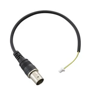
BNC coaxial cable assembly featuring a BNC interface, flexible black cable, strain relief, and a miniature board-side connector for RF signal routing, equipment integration, and test-system connections.
The product name creates much of the confusion.
Online listings may use “BNC splitter,” “BNC tee adapter,” and “BNC T connector” for products that look almost identical. Their electrical behavior may be completely different.
A direct tee normally has a simple internal arrangement:
- The three center contacts are electrically connected.
- The three connector shells share the same shield or reference path.
- No internal circuit transforms the impedance.
- No network guarantees equal power division.
- Output-to-output isolation is not defined.
The T-shaped body describes the mechanical arrangement. It does not prove that the product contains a matched splitting network.
Trace the three ports before trusting the product name
For a direct tee, a multimeter will normally show continuity from the center contact of one port to the center contacts of the other two ports. The outer bodies should also be continuous with each other, while the center contacts remain isolated from the shells.
That test helps confirm a direct topology. It does not confirm high-frequency performance.
A product described as a matched splitter needs more evidence. The specification should state:
- Nominal impedance
- Operating frequency range
- Insertion loss
- Return loss or VSWR
- Output-to-output isolation
- Amplitude balance
- Power rating
- DC path behavior
If the supplier provides only connector genders, body material, and continuity information, the part is probably a direct tee rather than a designed RF power divider.
Separate a tee from a matched power divider
| Requirement | Direct BNC Tee | Matched RF Splitter | Active Video Distributor |
| Internal connection | Shared electrical node | Resistive, transformer, or divider network | Buffered electronic outputs |
| Port matching | Not guaranteed | Designed for stated impedance | Designed for stated video impedance |
| Output isolation | Poor or undefined | Specified in dB | High due to active buffering |
| Equal division | Not guaranteed | Defined within a frequency range | Reproduces the input at multiple outputs |
| External power | No | Usually no | Yes |
| Typical use | Monitoring or local termination | RF signal division | Multi-monitor video distribution |
A matched splitter may still use three BNC interfaces, but its internal circuit is doing the real work. The connector body alone does not create the match.
For more background on the BNC interface itself, see the TEJTE guide to BNC connectors, uses, and adapters.
BNC product identity decision tree
Use this check before approving a marketplace listing:
Do not accept “splitter” as sufficient technical identification. Fix the topology in the purchase description.
What Load Does the Source See After a Tee Is Added?
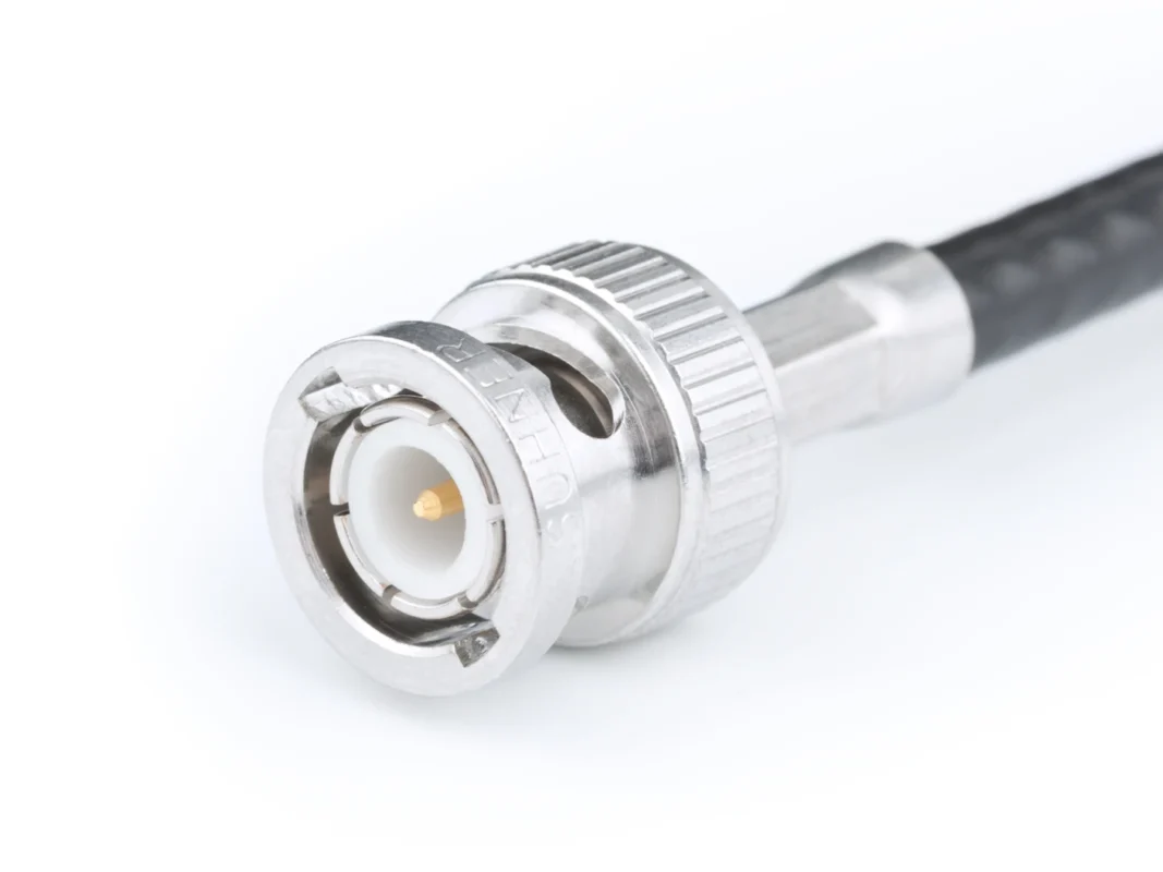
A tee connects branches. It does not automatically protect the source from the combined load.
For two resistive loads, the approximate parallel impedance is:
Convert the combined load into reflection risk
The reflection coefficient at an idealized 50-ohm node is:
This calculation is a screening tool, not a complete model of the physical setup. At RF and with fast digital edges, cables behave as transmission lines. Branch length, connector discontinuities, source impedance, cable velocity factor, and load input structure all affect the observed result.
Still, the 25-ohm calculation explains a common bench symptom: the signal amplitude changes immediately after the second terminated instrument is connected.
Distinguish high-impedance monitoring from dual termination
| Branch A | Branch B | Approximate source load | Practical concern |
| 50Ω | 50Ω | 25Ω | Strong mismatch |
| 50Ω | 1MΩ | Approximately 50Ω | Often acceptable at low frequency; cable stub still matters |
| 75Ω | 75Ω | 37.5Ω | Video amplitude and reflection risk |
| 75Ω | High-Z | Approximately 75Ω | May work in an approved loop-through arrangement |
| 50Ω | Open cable | Frequency-dependent | Open branch acts as a stub |
A high-impedance input is not the same as a terminated RF input. Two oscilloscopes set to 1 MΩ may create relatively light DC loading, but their cables and input capacitance can still alter fast edges.
Which Three-Port Gender Pattern Matches the Bench Setup?
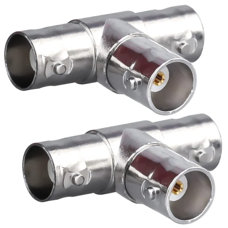
A tee can be electrically correct and mechanically unusable.
Start with the three existing interfaces rather than selecting the product from a catalog photo:
- What gender is the source or instrument port?
- What gender is the cable connector?
- What gender is the terminator?
- Will the tee mount directly to an instrument?
- Is there enough clearance to rotate both bayonet couplings?
- Will one branch interfere with an adjacent oscilloscope channel?
A common bench arrangement uses a BNC male to dual female adapter. The male center port plugs directly into a female oscilloscope input. One female branch accepts the incoming BNC male cable, while the other accepts a male terminator.
Avoid correcting the wrong tee with adapter stacks
This arrangement creates unnecessary interfaces:
Oscilloscope→ Gender changer→ BNC tee→ Barrel coupler→ Cable A better BOM selects the correct tee from the beginning:
Oscilloscope female input→ BNC male-to-dual-female tee→ BNC male cable + BNC male terminator Every added interface introduces another contact pair, another dimensional tolerance, and another possible impedance discontinuity. Adapter stacks also put more leverage on the oscilloscope input.
The front connector genders must be written separately in the RFQ. “BNC tee” is not enough.
Where Should the 50-Ohm Termination Sit on an Oscilloscope?
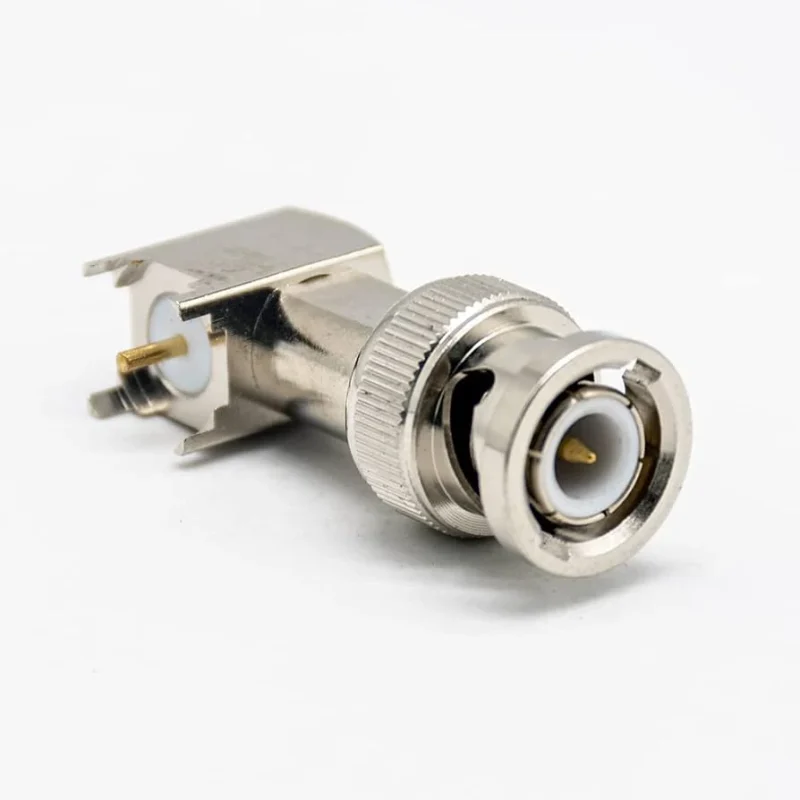
The termination belongs at the receiving end of the transmission line, as close as practical to the intended measurement reference plane.
Before adding an external terminator, check the oscilloscope input setting.
Prevent accidental double termination
Consider this setup:
50Ω source→ 50Ω cable→ BNC tee→ oscilloscope set to 50Ω→ external 50Ω terminator on second branch At the tee, the scope input and external terminator are approximately in parallel. The result is again close to 25 ohms.
The operator may interpret the lower amplitude as a source problem, cable loss, or instrument calibration error. In reality, the load was changed.
Check whether a feed-through terminator is cleaner
A feed-through termination may eliminate the need for a separate tee in some measurement arrangements. The signal enters one side, sees the intended termination at the receiving point, and continues through the accessory only where the system design requires it.
The correct option depends on the instrument, source, probe, and calibration method. The TEJTE 50-ohm BNC terminator guide explains the difference between a true terminator and a feed-through termination in more detail.
A practical topology card is useful at the bench:
| Scope input | External termination | Likely arrangement |
| Internal 50Ω | None | Direct cable connection |
| 1MΩ | 50Ω feed-through | Terminate at the scope input |
| 1MΩ with tee | One 50Ω branch | Review stub length and total loading |
| Internal 50Ω | External 50Ω | Usually a double-load error |
| Unknown | Unknown | Stop and check the instrument manual |
| Input return loss | VNA | Project limit |
| Branch transmission | VNA | Recorded in dB |
| Amplitude balance | VNA | Maximum difference |
| Output isolation | VNA | Required only if claimed |
| Bayonet retention | Mate/unmate test | Pass / fail |
| Body looseness | Mechanical inspection | None / reject |
| Final classification | Engineering review | Tee / splitter / reject |
How Can an Open Branch Distort a Fast Edge?
An open branch is not electrically invisible.
Once a cable is attached to the unused side of the tee, that branch becomes a transmission-line stub. The signal travels down the branch, reaches the open end, reflects, and returns to the tee.
Possible symptoms include:
- Ringing
- Overshoot
- Undershoot
- Delayed steps
- Frequency ripple
- Cable-length-dependent amplitude changes
- Different results when the unused cable is moved or replaced
Compare stub delay with signal rise time
The approximate one-way propagation time is:
Where:
- (L) is the stub length.
- (VF) is the cable velocity factor.
- (c) is the speed of light.
- (t_r) is the signal rise time.
A useful internal screening ratio is:
A larger ratio means the returned reflection is more likely to appear as a visibly separate disturbance rather than blending into the original transition.
This ratio is not an industry acceptance standard. Use it to decide which setups deserve waveform testing.
Remove the branch before trying to compensate for it
The simplest fixes are usually physical:
- Remove the unused cable.
- Shorten the branch.
- Terminate it correctly.
- Move the monitoring point.
- Use a suitable high-impedance probe.
- Replace the tee with a matched splitter.
Adding more adapters rarely solves a stub problem. It usually adds more discontinuities.
For branch delay and cable selection, the TEJTE RG cable guide provides a broader comparison of coaxial cable structures and propagation considerations.
Should the Tee Be 50 Ohms or 75 Ohms?
BNC connectors from different impedance families may physically mate. That does not make the signal path electrically consistent.
Use a 50-ohm system for typical RF and laboratory equipment such as:
- Oscilloscopes
- RF signal generators
- Function generators
- Spectrum analyzers
- Frequency counters
- RF test fixtures
- Laboratory coaxial measurement chains
Use a documented 75-ohm system for compatible video paths such as:
- Analog composite video
- CCTV
- Broadcast video equipment
- Selected digital-video coaxial systems
Audit the entire chain:
Source port→ Tee or splitter→ Branch cable A→ Branch cable B→ Load A→ Load B→ Any external terminator One correctly specified tee cannot correct a 50/75-ohm mixture elsewhere in the path.
The TEJTE BNC cable selection guide covers the practical differences between 50-ohm RF and 75-ohm video cable systems.
Can One Video Feed Drive Two Displays Through a Tee?
A picture may appear on both displays and still be electrically wrong.
If both video inputs terminate in 75 ohms:
A passive tee does not transform that 37.5-ohm load back to 75 ohms.
Possible symptoms include:
- Lower video amplitude
- Reduced contrast or signal margin
- Reflections or ghosting
- Unstable synchronization
- Increased sensitivity to cable length
- One display affecting the other
Check for a high-impedance loop-through input
Some professional video devices provide:
- A high-impedance loop-through input
- A separate loop output
- Selectable 75-ohm termination
- One final terminated device at the end of the chain
In that arrangement, intermediate devices remain high impedance and only the final receiver provides the 75-ohm load.
Do not assume a monitor or DVR supports loop-through operation because it has two BNC connectors. Check the manual and termination switch.
Use active distribution for permanent video branches
An active video distribution amplifier is usually the safer choice when one source must feed:
- Multiple 75-ohm displays
- Independent long cable runs
- Different rooms or equipment racks
- Outputs requiring isolation
- A permanent CCTV distribution system
Which Device Should Replace a Tee for True Two-Way Distribution?
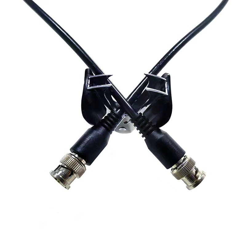
A pair of BNC to alligator clip test leads designed for temporary oscilloscope connections, low-frequency signal measurements, circuit troubleshooting, laboratory testing, and production test fixtures.
The replacement depends on the signal.
Use a resistive splitter for broadband matched bench work
A resistive splitter can provide:
- Broad frequency coverage
- Defined port impedance
- Predictable insertion loss
- Some isolation through the resistor network
- Simple passive construction
The trade-off is loss. Energy is dissipated in the network rather than being divided with ideal efficiency.
Use a transformer or Wilkinson divider for RF power division
A frequency-specific RF divider may provide:
- Controlled impedance
- Defined equal or unequal power division
- Better output isolation
- Specified amplitude balance
- Specified phase balance
- A documented operating band
Its performance must be checked across the required frequency range. A divider intended for one RF band should not be assumed to work from DC to its highest marked frequency.
Keep the tee for node access
A direct tee is still useful when the task is clearly defined:
- Add one high-impedance monitoring point.
- Mount a local termination at an instrument.
- Perform temporary low-frequency verification.
- Build a known loop-through arrangement.
- Access a service or calibration node.
The tee is not defective because it lacks output isolation. It is simply a different product.
What Tests Separate a Good Tee from a Risky One?
A BNC tee can pass visual inspection and continuity while still being unsuitable for the intended RF band.
Map continuity first
For a direct tee, verify:
- Center contact continuity across all three ports
- Shell continuity across all three ports
- No center-to-shell short
- Correct male and female interfaces
- Secure body assembly
- Normal bayonet engagement
Measure RF behavior under the correct termination conditions
For VNA testing:
- Calibrate at the intended reference plane.
- Connect the port under test.
- Terminate the other ports using the specified system impedance.
- Record input return loss.
- Measure transmission from the common port to each branch.
- Repeat the setup where port symmetry is relevant.
Do not demand power-divider isolation from a direct tee unless the supplier claimed that performance. If the product is sold as a matched splitter, request the exact test conditions.
BNC tee acceptance standard
Production buyers should also define sampling quantity, packaging protection, label format, and whether the supplier must preserve a reference sample.
What Specifications Must Be Fixed Before Ordering?
Write the product name by topology.
A direct tee can be described as:
Direct BNC T Connector BNC Male to Dual BNC Female 50 Ohm
A matched splitter should be described differently:
Two-Way Matched BNC RF Splitter 50 Ohm Specified Frequency Range Defined Insertion Loss and Output Isolation
Do not write only “BNC splitter.” That leaves the internal circuit undefined.
State the application, not only the connector arrangement
The supplier should know whether the part is intended for:
- Oscilloscope termination
- High-impedance signal monitoring
- Equal RF power division
- CCTV distribution
- Signal combining
- Calibration equipment
- Production test fixtures
The same connector arrangement may be acceptable for one task and wrong for another.
BNC T connector RFQ block
A useful BOM note might read:
BNC T connector, direct three-port topology, 50 ohm, BNC male common port to two BNC female branch ports, for oscilloscope termination node, nickel-plated body, gold-plated center contacts, drawing approval required, continuity and mechanical mating inspection before shipment.
That description is harder to misinterpret than “one BNC splitter.”
FAQ
Does a BNC T connector divide the input power equally?
Not necessarily. A direct BNC tee connects three ports to one electrical node but does not guarantee equal power division, matched impedance, or branch-to-branch isolation. The actual voltage and power at each branch depend on source impedance, load impedance, cable length, frequency, and termination. Use a designed RF splitter when equal division is required.
What happens when two 50-ohm instruments are connected to one tee?
Under a simplified parallel-load model, two 50-ohm inputs present approximately 25 ohms to the source. That mismatch can reduce the measured amplitude and increase reflections. A matched splitter or another approved measurement topology is safer when both instruments require 50-ohm termination.
Must an unused BNC tee port always be terminated?
A bare unused connector port does not create the same delay as a long cable branch, but an attached open cable can behave as a stub. Its effect depends on cable length, velocity factor, signal rise time, and frequency. Remove unused cables or terminate them correctly when waveform integrity matters.
Can two oscilloscopes monitor the same signal through a tee?
They may be able to when both scope inputs are high impedance and the cable branches are short enough for the required bandwidth. Two scopes set to internal 50-ohm termination create approximately a 25-ohm load and should not be connected through a direct tee without analyzing the source and measurement requirements.
Does the male port always act as the input?
No. A passive direct tee is normally bidirectional. Male and female describe the mechanical connector interfaces, not fixed signal direction. The user may call one port the common or input port for convenience, but the internal node itself does not enforce direction.
Can a 50-ohm BNC tee be used in a 75-ohm CCTV system?
It may physically connect, but it introduces an impedance inconsistency. For a permanent CCTV system, use a documented 75-ohm tee in an approved loop-through arrangement or an active video distribution amplifier when one source must drive multiple terminated inputs.
How can a buyer identify a real matched BNC splitter?
Check whether the datasheet specifies internal topology, operating frequency, port impedance, insertion loss, return loss, amplitude balance, and output isolation. A listing that provides only connector genders and body dimensions is more likely to describe a direct BNC tee.
A BNC T connector is useful when the goal is to access a known electrical node. It becomes risky when the buyer expects it to perform impedance transformation, equal RF division, or isolated video distribution.
Before ordering, fix five points: topology, impedance, all three connector genders, expected branch loads, and termination location. For matched distribution, request S-parameters and output-isolation data rather than relying on the T-shaped body or marketplace title.
For a custom BNC tee, matched splitter, or coaxial test assembly, provide the operating frequency, cable impedance, source impedance, load values, connector configuration, and required inspection method. Those details make it possible to separate a simple mechanical adapter from the RF component the system actually needs.
