
A BNC male to male cable looks straightforward: one BNC male connector at each end with a length of coaxial cable between them. On an RF test bench, however, a cable that physically connects two instruments may still produce unreliable measurements if its impedance, cable type, length, termination quality, or operating bandwidth is not clearly defined.
This cable format is commonly used to connect two devices equipped with BNC female ports. Typical examples include a signal generator connected to a test fixture, an RF source connected to a frequency counter, or a module output connected to a measurement instrument.
Before selecting a cable, engineers should confirm more than the connector name. A complete specification should identify both connector genders, the nominal impedance, the coaxial cable family, the required assembly length, and the electrical acceptance limits.
Readers who need a broader introduction to BNC interfaces can first review the BNC connector guide. This article focuses specifically on short BNC male-to-male jumpers used for RF testing, especially assemblies made with RG316 coax.
When Should You Connect Two BNC Female Ports Directly?
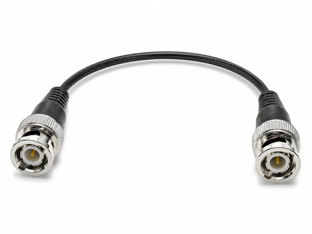
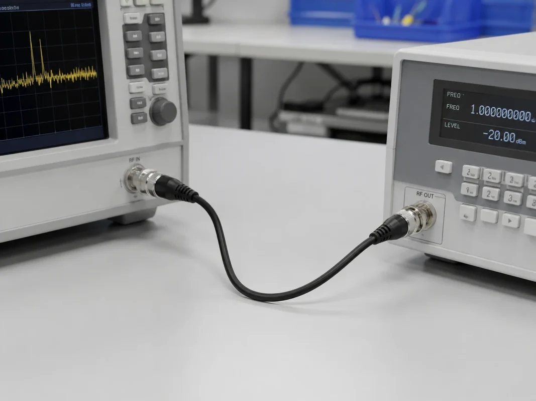
A BNC male-to-male jumper is appropriate when the source equipment and destination equipment both have BNC female interfaces.
For example, a bench signal generator may have a female BNC output, while a test fixture has a female BNC input. The cable therefore needs a BNC male connector at both ends.
The same arrangement may be used for:
- A signal generator connected to a test fixture
- An RF source connected to a frequency counter
- A module output connected to an oscilloscope
- Two sections of a BNC patch panel
- A test rack connected to laboratory equipment
- Short RF signal routing between instruments
The first step is to map the complete connection:
Do not select cable gender from the direction of the signal. Terms such as “input cable” and “output cable” describe equipment functions, not connector gender.
A BNC male connector can be used on either the source side or the destination side. A passive coaxial cable normally carries an RF signal in either direction.
Use one jumper instead of two cables and a coupler
Two BNC female ports can also be connected through a more complicated arrangement:
This arrangement may work, but it introduces an additional cable and an additional mated interface. Every extra transition creates another location where mechanical wear, contamination, impedance variation, or poor contact may affect the RF path.
A single male-to-male jumper provides a cleaner arrangement:
BNC female port→ BNC male-to-male cable→ BNC female port
The direct cable has fewer connection points, is easier to label, and reduces the number of components that must be inspected during troubleshooting.
A coupler remains useful when an existing cable must be extended temporarily. For a permanent test setup or a repeatable production station, a cable manufactured to the correct length is usually easier to control. More guidance on longer cable routes is available in the BNC extension cable guide.
How Do You Confirm Both Ends Are BNC Male?
The phrase “BNC-to-BNC cable” is not precise enough for purchasing. It does not tell the supplier whether the required ends are male, female, or a combination of the two.
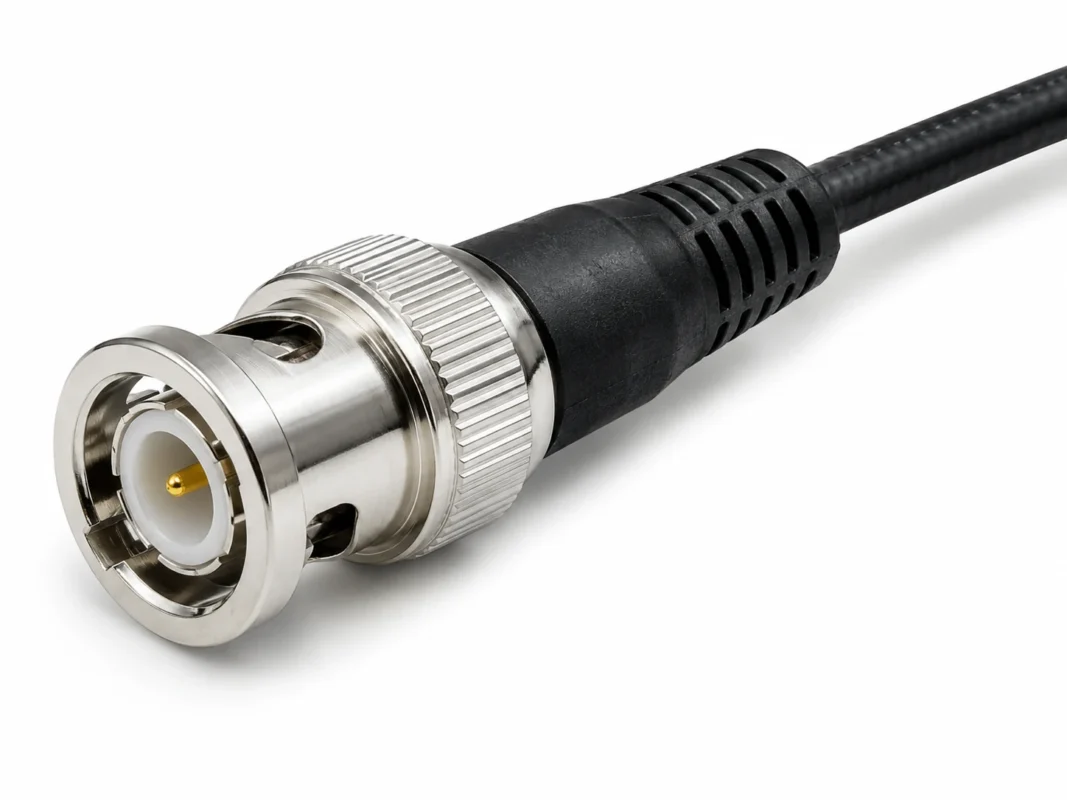
A BNC male connector normally has two recognizable features:
- A center contact pin
- A rotating bayonet coupling sleeve
The male connector is pushed onto a female jack and then rotated so that the bayonet sleeve locks onto the two studs on the female interface.
Check the center contact
The center contact provides the quickest gender check. A standard BNC male connector normally uses a protruding center pin, while the mating female connector uses a socket.
Do not rely only on the outer body shape. Connector photographs taken from the side may hide the center contact, making male and female versions difficult to distinguish.
For purchasing approval, request at least one front-facing image or a connector drawing that clearly shows the center contact.
Check the bayonet structure
The coupling sleeve on a BNC male connector rotates during mating. The female jack normally has two external studs that fit into the slots of the male sleeve.
The bayonet structure allows fast connection and removal, which is one reason BNC cables remain common on frequently reconfigured test benches.
Before bulk production, verify that the sleeve rotates smoothly and locks without excessive looseness. A connector that feels secure mechanically is less likely to move during measurement, although mechanical inspection alone cannot verify RF performance.
Use an unambiguous purchasing description
Avoid descriptions such as:
- BNC input cable
- BNC output lead
- Double BNC cable
- BNC-BNC wire
- BNC connector cable
A better description is:
- BNC Male to BNC Male
- Straight to Straight
- 50 Ohm
- RG316 Coaxial Cable
- Specified Overall Length
The assembly drawing should also define how length is measured. Depending on the supplier, cable length may refer to:
- Cable jacket length
- Connector tip-to-tip length
- Connector reference-plane length
- A nominal length excluding connector bodies
Without a defined reference plane, two suppliers may interpret a “500 mm cable” differently.
BNC Interface Confirmation Card
| Confirmation field | Required entry |
| Equipment port A | BNC male / BNC female |
| Equipment port B | BNC male / BNC female |
| Cable end A | BNC male |
| Cable end B | BNC male |
| Center contact | Pin confirmed |
| Coupling style | Bayonet |
| Impedance | 50Ω / 75Ω |
| Orientation | Straight / right angle |
| Drawing reviewed | Yes / no |
| Compatibility result | Pass / review |
Why Use RG316 for a Short BNC Jumper?
RG316 is often selected for compact BNC jumper cables because it has a relatively small diameter and can be routed through crowded test fixtures more easily than thicker coaxial cable.
The cable is frequently used where:
- Instruments are positioned close together
- The jumper must pass behind a rack
- A test fixture has limited internal space
- Heavy cable could place stress on the equipment port
- Heat resistance is more important than minimum attenuation
- The assembly is short enough for its loss to remain acceptable
RG316 commonly uses a PTFE dielectric and an FEP outer jacket. These materials make the cable suitable for applications where temperature resistance and compact routing are important.
However, RG316 should not automatically be described as a low-loss cable. Its small diameter brings mechanical advantages, but the same compact construction generally results in more attenuation than a thicker cable over the same frequency and distance.
Balance flexibility against attenuation
A short RG316 BNC cable may perform well between nearby instruments. As cable length and operating frequency increase, its attenuation becomes more important.
The selection should therefore be based on the complete application:
For a short jumper inside a fixture, reducing cable diameter may be more valuable than saving a small fraction of a decibel.
For a longer bench route, a thicker cable such as RG58 may offer a more useful loss margin. The differences between the two cable families are discussed in more detail in the RG316 versus RG58 guide.
When should you consider RG58 or another cable?
RG58 or another larger coaxial cable may be more appropriate when:
- The cable run is relatively long
- The highest operating frequency is near the system limit
- Maximum insertion loss is tightly controlled
- The RF power is higher
- The route has enough space for a larger bend radius
- The assembly will remain permanently installed
- Cable weight will not pull on the equipment port
- Repeated tight bending is not required
In some test systems, a hybrid approach is useful. A thicker low-loss cable may cover most of the route, while a short, flexible RG316 jumper is used near the device or fixture.
Does a 0–6 GHz Label Guarantee Usable Results?
No. A “0–6 GHz” label does not, by itself, define the performance of the finished cable assembly.
The stated range may refer to the connector design, a component family, or a general product category. It does not guarantee that every cable length will have the same insertion loss, return loss, or measurement repeatability at 6 GHz.
The finished assembly is affected by several elements:
- Connector geometry
- Connector impedance
- Cable attenuation
- Cable length
- Center-conductor termination
- Shield termination
- Crimp consistency
- Soldering quality
- Cable bending
- Connector wear
- Additional adapters in the path
A connector may be described as suitable for a certain upper frequency, but the complete assembly may still exceed the customer’s insertion-loss limit because of cable length.
Likewise, a short assembly may have acceptable insertion loss but poor return loss if the connector transition is not properly controlled.
Separate connector capability from assembly performance
A complete evaluation should distinguish between:
Connector frequency capability
The upper frequency at which the connector design is intended to operate under specified conditions.
Cable attenuation
The signal loss contributed by the coaxial cable at a particular frequency and length.
Assembly insertion loss
The total transmitted signal loss measured through the finished cable.
Assembly return loss or VSWR
The amount of signal reflected because the assembly does not perfectly match the system impedance.
Mechanical repeatability
The change in measured performance after the connector is disconnected, reconnected, or the cable is repositioned.
A cable can physically transmit a signal at 6 GHz without meeting the measurement accuracy required by a specific project. “Signal present” and “acceptable RF performance” are not the same acceptance criteria.
Define usable bandwidth from the application
The useful operating range should be based on the customer’s limits rather than a broad product label.
Define:
- Highest operating frequency
- Cable assembly length
- Maximum permitted insertion loss
- Minimum permitted return loss
- Maximum VSWR
- Required measurement repeatability
- Instrument uncertainty
- Number of other transitions in the path
For example, a 200 mm jumper and a 2 m cable made from the same components should not be expected to have identical insertion loss at the upper end of the band.
Request a VNA report when the upper band matters
When the application approaches the claimed upper frequency, request a vector network analyzer measurement of the finished assembly.
A useful report should include:
- S11 or return-loss data
- S21 or insertion-loss data
- Sweep start frequency
- Sweep stop frequency
- Calibration method
- Calibration reference planes
- Cable assembly length
- Sample or serial identification
- Test date
- Test fixture or adapter details
A VNA evaluates both reflected and transmitted signals, which makes it suitable for checking S11, S21, return loss, and cable transmission behavior. The measurement principles are explained in the Rohde & Schwarz VNA fundamentals reference.
Do not approve an assembly solely from a generic cable attenuation table. The finished product should be tested in the same configuration that will be supplied.
How Much Loss Can the RF Path Accept?
A loss budget converts a vague requirement such as “low loss” into an engineering limit.
The basic cable-loss calculation is:
Where:
- Attenuation is expressed in dB/m
- Cable length is expressed in meters
- Cable loss is expressed in dB
This calculation estimates the contribution of the coaxial cable itself. It does not automatically include connector transitions, adapters, couplers, or mismatch loss.
Add the other interfaces
A more complete planning formula is:
The purpose of the formula is not to create false precision. Connector loss varies with frequency, design, manufacturing quality, mating condition, and measurement method.
Instead, the estimate helps answer practical questions:
- Is RG316 suitable for this length?
- Can one adapter be removed?
- Should the cable be shortened?
- Is a thicker coaxial cable needed?
- Does the assembly need an RF test report?
- Is enough margin available for production variation?
Keep a realistic margin
A calculated result that exactly equals the permitted limit is not a robust design.
Allow margin for:
- Sample-to-sample differences
- Connector remating variation
- Instrument uncertainty
- Calibration drift
- Temperature
- Cable bending
- Connector contamination
- Manufacturing tolerances
- Long-term wear
Suppose a project allows a maximum path loss of 2.0 dB. If the estimated assembly loss is already 1.95 dB before manufacturing variation and measurement uncertainty are included, the cable has almost no practical margin.
A better design may shorten the jumper, remove an unnecessary coupler, or select a lower-loss cable.
BNC Jumper Loss Budget Calculator
| Field | Symbol or calculation |
| Operating frequency | f, MHz or GHz |
| Cable length | L, m |
| Verified attenuation | α(f), dB/m |
| Calculated cable loss | α(f) × L |
| Number of extra interfaces | N |
| Estimated interface loss | N × IL interface |
| Design margin | Project-defined value |
| Total estimated loss | Cable + interfaces + margin |
| Maximum allowed loss | IL limit |
| Remaining margin | IL limit − total loss |
| Decision | Pass / shorten / change cable |
The attenuation values used in this calculation should come from the final supplier specification or from an agreed test report. If an image, catalog, and datasheet show conflicting values, the discrepancy should be resolved before the purchase order is approved.
How Do You Keep the Entire Connection at 50 Ohms?
A 50-ohm BNC cable cannot maintain a 50-ohm signal path by itself. The complete chain must be reviewed.
Check the impedance of:
- Signal generator output
- Oscilloscope input
- Spectrum analyzer input
- Frequency counter input
- Test fixture
- BNC connectors
- Coaxial cable
- Couplers and adapters
- Tee connectors
- Final termination
BNC connectors are available in both 50-ohm and 75-ohm versions. The two versions may appear similar and may physically mate, but that does not make them electrically interchangeable in a controlled RF measurement system.
Avoid mixing RF and video components
A video cable fitted with BNC connectors is not automatically suitable for a 50-ohm RF test system. Many video and broadcast systems use 75-ohm components.
Problems occur when a laboratory stores 50-ohm RF jumpers and 75-ohm video cables in the same area without clear labels.
A useful labeling system includes:
Color labels or heat-shrink markers can reduce selection errors, but written impedance identification should still be included.
For a more complete discussion of end-to-end matching, see the TEJTE guide to maintaining a true 50-ohm BNC signal chain.
Confirm the oscilloscope input setting
Some oscilloscopes offer both a high-impedance input and an internal 50-ohm input. Others require an external 50-ohm terminator.
This difference affects the signal amplitude seen by the instrument.
Before connecting a source, check:
- Whether the input is set to 1 MΩ or 50Ω
- Whether an external terminator is installed
- The maximum voltage permitted in 50-ohm mode
- Whether a tee connection is being used
- Whether another instrument is connected in parallel
A tee connection can create a second signal path and change the effective load. The cable cannot correct an incorrect termination arrangement.
Which Cable Length Works Best on a Test Bench?
The best cable length is the shortest length that reaches the equipment naturally without pulling on the connector.
Do not select length from straight-line distance alone. The real route may include:
- Horizontal movement
- Vertical movement
- Space behind connectors
- Cable bend radius
- Instrument movement
- Fixture access
- A service loop
- Strain-relief points
A cable that is exactly equal to the measured straight-line distance may be too short once connector access and bending are considered.
Avoid a cable that is too short
An overly short cable can pull sideways on BNC ports. This may cause:
- Incomplete bayonet locking
- Connector movement during testing
- Wear on the equipment jack
- Stress on an internal PCB
- Unstable measurement results
- Damage when equipment is moved
The cable should rest naturally after installation. It should not act like a tensioned strap between two instruments.
Avoid unnecessary excess length
A cable that is much longer than required creates a different set of problems:
- Higher insertion loss
- More cable clutter
- Accidental loops and coils
- Greater risk of snagging
- More difficult cable identification
- Increased bending during handling
- Greater chance of connecting the wrong instrument
The goal is not “as short as possible” in an absolute sense. The goal is the shortest strain-free routed length.
Standardize several laboratory lengths
A laboratory or production facility may benefit from standardizing a small group of cable lengths, such as:
- Short fixture jumper
- General bench jumper
- Rack connection jumper
- Custom service jumper
The exact lengths should be based on the equipment layout rather than copied from another laboratory.
Custom Length Worksheet
| Measurement | Unit |
| Horizontal distance | mm |
| Vertical distance | mm |
| Connector access allowance | mm |
| Service loop | mm |
| Calculated routed length | mm |
| Selected standard length | mm |
| Excess length | mm |
| Strain-free fit | Pass / fail |
When specifying length to a manufacturer, also state the permitted tolerance and the measurement reference points.
Can This Cable Replace a Precision RF Test Lead?
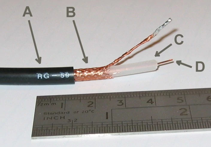
Cutaway image of an RG58 coaxial cable showing its main construction layers. The image supports comparison between RG58 and smaller RG316 cable when selecting a BNC jumper based on attenuation, routing space, flexibility and cable length.
A standard RG316 BNC cable assembly may be suitable for general laboratory signal routing, functional testing, and equipment interconnection.
That does not automatically make it a precision or calibration-grade RF test cable.
Precision measurement cables may require additional performance controls, including:
- Phase stability under flexure
- Amplitude stability under flexure
- Tightly controlled insertion loss
- Defined connector repeatability
- Serialized VNA data
- Controlled mechanical bending
- High mating-cycle connectors
- Individual traceability
- Defined storage and handling procedures
A general interconnect may pass continuity and basic VNA testing while still showing too much variation for a sensitive measurement application.
Define repeatability before using the term “test cable”
The word “test cable” is often used loosely. A more useful specification defines how repeatability will be evaluated.
One possible procedure is:
- Measure S11 and S21 with the cable in a defined position.
- Disconnect both ends.
- Reconnect the cable.
- Repeat the measurement.
- Perform several mating cycles.
- Reposition the cable gently.
- Measure again.
- Compare the changes.
The acceptance limit should state the maximum permitted variation rather than merely saying the cable must be “stable.”
Select the correct product grade
A practical classification may include:
General RF interconnect
For basic equipment connection and noncritical signal routing.
Production functional-test jumper
For repeated pass/fail testing where measurement limits have adequate margin.
Laboratory measurement cable
For engineering measurements requiring controlled insertion loss, return loss, and repeatability.
Calibration-grade cable
For high-precision work requiring tighter phase, amplitude, connector, handling, and traceability controls.
An ordinary BNC male-to-male RG316 assembly should not be marketed as calibration-grade solely because its connectors are described as operating up to 6 GHz.
How Should Samples Be Tested Before Bulk Ordering?
A sample evaluation should confirm both workmanship and electrical performance.
The test plan should reflect the final application. A continuity test alone is not enough for a cable that will be used at RF frequencies.
Inspect the workmanship
Check:
- Correct connector genders
- Center pin alignment
- Bayonet sleeve movement
- Connector body looseness
- Crimp consistency
- Cable entry and strain relief
- Heat-shrink condition
- Jacket scratches or cuts
- Cable diameter
- Assembly length
- Labeling
- Packaging protection
The cable should not rotate inside the connector termination when light force is applied.
Measure continuity and isolation
Basic electrical checks include:
- Center conductor continuity
- Shield continuity
- Center-to-shield isolation
- Intermittent contact during light movement
Continuity verifies that the conductors are connected. It does not verify characteristic impedance or high-frequency signal integrity.
Test the actual operating frequencies
A useful RF test plan includes:
- A low-frequency reference point
- The primary operating frequency
- The highest operating frequency
- The longest required cable length
- Repeated mating
- Light flexing
- The actual adapters or fixtures used by the customer
Testing only at a convenient mid-band frequency may miss problems near the application’s upper limit.
BNC Cable Assembly Acceptance Standard
| Inspection item | Test method | Acceptance field |
| Connector gender | Visual and drawing | Correct / incorrect |
| Assembly length | Tape or caliper | Target ± tolerance |
| Center continuity | DMM | Pass / fail |
| Shield continuity | DMM | Pass / fail |
| Center-to-shield isolation | DMM or megohmmeter | Project limit |
| Return loss | VNA | Minimum dB |
| VSWR | VNA | Maximum ratio |
| Insertion loss | VNA | Maximum dB |
| Remating variation | Repeated measurement | Maximum change |
| Flex sensitivity | Light handling test | Stable / unstable |
| Workmanship | Visual inspection | Approved / rejected |
| Final disposition | Combined review | Approved / rejected |
Keep the approved sample, drawing, test report, and packaging method as the production reference.
What Must Be Included in the Purchase Specification?
A clear RFQ reduces the chance of receiving the wrong connector gender, impedance, length, or performance level.
Start by writing both connector ends separately:
Do not rely on “BNC-BNC cable.”
Define the cable and mechanical requirements
Include:
- Coaxial cable family
- Nominal outer diameter
- Jacket material
- Jacket color
- Overall assembly length
- Length measurement method
- Length tolerance
- Straight or right-angle orientation
- Strain-relief requirement
- Product marking
- Packaging method
When reviewing supplier images, remember that a nominal cable diameter and a measured finished diameter may not be identical. The approved value should come from the final controlled specification.
Define the electrical requirements
Include:
- Nominal impedance
- Operating frequency range
- Maximum insertion loss
- Frequency at which insertion loss is specified
- Minimum return loss or maximum VSWR
- RF power, when relevant
- Test method
- Calibration reference planes
- Whether every cable or only samples must be tested
A frequency range without an insertion-loss or return-loss limit leaves too much room for interpretation.
Request only necessary documents
Depending on the project, documents may include:
- Mechanical drawing
- Product specification
- VNA test report
- First-article inspection report
- Material declaration
- RoHS documentation
- Lot traceability
- Individual test record
- Packing list
- Certificate of conformity
Not every project needs every document. Requiring unnecessary paperwork can increase cost and lead time without improving the finished assembly.
FAQ
Can a BNC male-to-male cable connect two oscilloscopes?
It may physically connect two BNC female ports, but first check the signal direction, output level, input mode, impedance, termination, and voltage limits. Two instrument ports should not be connected merely because the connectors fit.
Is every BNC male-to-male cable 50 ohms?
No. BNC products are available in both 50-ohm and 75-ohm versions. Confirm the connectors, coaxial cable, equipment ports, couplers, and termination.
Why use RG316 instead of RG58?
RG316 is smaller and easier to route around compact fixtures. RG58 may be preferable when a longer route, lower attenuation, or greater power margin is more important.
Does reversing the cable change its RF behavior?
A passive male-to-male cable normally carries signals in either direction. Small differences may still appear if the two connector terminations are not equally consistent.
Can continuity testing qualify the cable?
No. Continuity confirms the electrical path but does not verify impedance, insertion loss, return loss, VSWR, or performance at the operating frequency.
