BNC Extension Cable Length, Loss & Routing Guide
Nov 10,2025
Preface
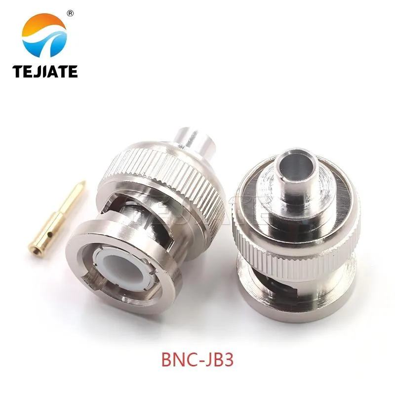
Figure is in the "Which BNC bulkhead fits your panel thickness?" section. Serving as a complement to the BNC-J-1.5, it visually presents a variant designed for thicker panels, expanding the reader's selection range.
If you’ve ever pushed a signal line a few meters too far, you’ve probably seen it happen — a trace that once looked perfect starts to blur, ghost, or flicker.
That’s the quiet warning of a BNC extension cable losing its headroom.
At TEJTE, we work with signal paths daily. Our benches run full of oscilloscopes, analyzers, and cables — from the BNC-JB3 50 Ω weld-type jack to precisely matched RG58, RG59, and LMR-240 coax. Over time, we’ve learned that “just a little extra length” can quietly shift return loss, noise floor, and measurement reliability.
This guide lays out what those losses really look like, how far you can safely run an extension, when to choose 50 Ω versus 75 Ω, and a few routing habits that save you hours of troubleshooting later.
How long can a BNC extension cable run before loss breaks your signal?
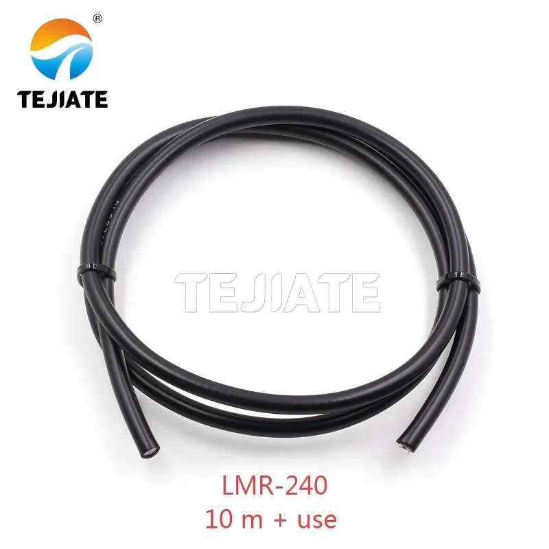
This image aims to show the robust appearance, thicker outer diameter (6.1mm) of LMR-240 cable, and its application examples in outdoor environments (e.g., rooftops, antenna masts), reinforcing its positioning as a long-distance, low-loss solution.
Signal strength never disappears all at once — it fades, one dB at a time. To see where the limits sit, you can model the total insertion loss as:
[ IL_{total}= \alpha_{cable} \times L + N_{conn} \times IL_{conn} ]
where
• α (cable attenuation) = loss per meter (dB/m) at the operating frequency
• L = run length (m)
• IL_conn ≈ 0.05 – 0.10 dB per BNC joint
• N_conn = number of connectors or couplers
For most RF test paths, try to stay under 1 dB total loss; in video CCTV use, around 3 dB is still acceptable.
Measured attenuation (20 °C / sea level)
| Cable Type | Impedance (Ω) | Freq (MHz) | Loss (dB/100 m) | Conn Loss (dB/pc) | Practical Notes |
|---|---|---|---|---|---|
| RG58 | 50 ± 2 | 100 | 7.66 | 0.08 | Green ≤ 1 dB @ <15 m; Yellow ≤ 2 dB @ <25 m |
| 900 | 43.2 | ||||
| 1500 | 69.6 | ||||
| RG59 | 75 ± 3 | 100 | ~ 4.5 | 0.08 | Used for video links up to 300 m |
| 900 | ~ 24 | ||||
| 1500 | ~ 38 | ||||
| LMR-240 | 50 | 100 | 5.0 | 0.05 | Low-loss choice for long RF runs |
| 900 | 24.8 | ||||
| 1500 | 32.4 |
Color key: ✅ Green – safe within budget | ⚠ Yellow – borderline | 🔴 Red – exceeds budget
Example:
Using TEJTE RG58, attenuation ≈ 0.0766 dB/m @ 100 MHz. A 10 m run with two BNCs adds about 0.9 dB total loss — comfortably inside the 1 dB budget for RF instrumentation.
Small details matter: coil memory, temperature, and moisture can nudge attenuation upward by ~0.1 dB per 10 m.
For long outdoor routes, many engineers switch from RG58 bnc coaxial cable to LMR-240 — it cuts roughly 25–30 % of the loss at 1 GHz without giving up flexibility.
(Internal anchor → “Verify return loss after extension” links later to 50 Ohm BNC Terminator Guide)
Should you choose 50 Ω or 75 Ω for the extension path?
This one decision sets the tone for your entire system.
50 Ω bnc extension cables dominate lab benches, RF modules, and test gear because they optimize power transfer.
75 Ω bnc cables live in CCTV and broadcast chains where voltage fidelity matters more than wattage.
Mix them and the system stops behaving predictably. One mismatched section can drive VSWR from 1.20 to 1.6 or higher — roughly 10 % of your signal power bouncing back.
In TEJTE’s own tests, pairing a BNC-JB3 50 Ω connector with RG58 kept VSWR ≤ 1.20 through 3 GHz (IEC 60169-8 verified).
Dropping in a 75 Ω segment raised return loss from –26 dB to –14 dB — instantly visible on an oscilloscope edge.
| Application | Recommended Cable | Impedance | Freq Range | Loss @ 1 GHz (dB/m) |
|---|---|---|---|---|
| RF Bench / Test Gear | RG58 / LMR-240 | 50 Ω | DC – 6 GHz | 0.24 / 0.18 |
| CCTV / Broadcast Video | RG59 BNC cable | 75 Ω | DC – 2 GHz | 0.24 |
| Hybrid Panels | Use BNC-KKY feed-through coupler + proper termination | Match segment | — | — |
A good habit: label every jumper with its impedance. When someone adds a “spare” bnc to bnc cable months later, you’ll know exactly whether it belongs.
(Reserved anchor → “Use a feed-through at panel entries” to BNC Coupler Selection Guide)
RG59 or RG58 for this run — how do you pick without overthinking?
It’s easy to fall down a rabbit hole of datasheets, but the practical rule is simple:
pick by impedance first, then by loss and flexibility.
For RF and test benches, 50 Ω RG58 bnc cable remains the everyday workhorse.
It’s light, bends easily, and terminates cleanly with BNC-JB3 connectors.
At 100 MHz it loses only 7.66 dB per 100 m (≈ 0.0766 dB/m).
For a ten-meter patch you barely feel the loss.
On the other hand, RG59 bnc cable (75 Ω) shines in CCTV and video feeds.
Its copper braid and thicker 6.1 mm OD jacket hold up better outdoors, and attenuation stays under 5 dB/100 m at 100 MHz — plenty margin for cameras under 300 m.
| Property | RG58 (50 Ω) | RG59 (75 Ω) |
|---|---|---|
| Outer Diameter (mm) | ≈ 5.0 | ≈ 6.1 |
| Attenuation @ 100 MHz (dB/100 m) | 7.66 | 4.5 |
| Minimum Bend Radius (mm) | 50 | 60 |
| Frequency Limit (GHz) | Up to 6 | Up to 2 |
| Typical Use | RF Test / Instrumentation | CCTV / Video Distribution |
| Recommended Connector | BNC-JB3 (50 Ω) | BNC-KKY feed-through (75 Ω) |
If the path runs longer than 30 m at high frequency, consider stepping up to LMR-240 bnc coaxial cable, which cuts roughly 30 % off the loss of RG58.
The Understanding RF Cables Guide covers that broader cable family if you want the deeper math.
Can a BNC-to-BNC patch solve your extension more cleanly?
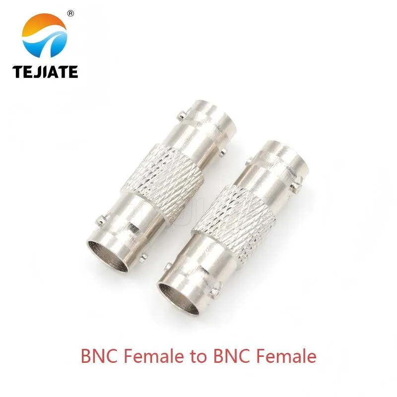
Figure is located in the "Which female-to-female orientation avoids extra adapters?" section. It clearly shows the form factor of the most common "barrel" coupler, helping readers understand its physical difference from feed-through connectors and providing a visual reference when discussing connector orientation, enclosure wiring, and avoiding adapter stacks.
Every extra joint introduces a reflection. Still, sometimes the neatest answer is a short bnc to bnc cable rather than another coupler.
A direct male-to-male bnc extension cable eliminates one mechanical gap and keeps impedance continuous through the barrel.
It also means one fewer surface that can oxidize — small win, big difference for long-term reliability.
But couplers do have their place.
A BNC-KKY feed-through (female-to-female) connector is ideal for panel mounts or rack-front bulkheads.
If the setup changes often, a detachable coupler spares your permanent line from wear.
In stable systems, though, order the proper length cable and avoid stacking adapters.
| Configuration | Extra Loss (dB) | Reflection Risk | Best Use Case |
|---|---|---|---|
| Single patch (BNC-M to BNC-M) | ≤ 0.05 | Low | Lab jumpers ≤ 10 m |
| Coupler + two cables | ≈ 0.10 – 0.15 | Medium | Temporary joins |
| Two couplers in series | > 0.20 | High | Avoid if possible |
Before cutting, double-check whether your equipment has front-panel access.
If so, one feed-through BNC adapter keeps everything serviceable from the outside — a trick borrowed from our own test racks at TEJTE Labs.
That same principle appears in the BNC Coupler Selection Guide, which dives deeper into panel-mount best practices.
How do you route through conduit without damaging the cable?
You can buy the perfect coax and ruin it in five minutes of bad routing.
Most damage happens not from voltage or moisture but from tight bends and abrasive pulls through conduit.
Follow the 40 % fill-ratio rule:
add up the cross-sectional area of all cables, divide by the conduit area, and stay under 0.4.
That leaves enough air space for friction reduction and heat dissipation.
Also mind bend radius — every bnc extension cable has a limit.
For RG58, that’s ≈ 50 mm; for RG59, ≈ 60 mm; for LMR-240, ≈ 61 mm (dynamic).
Exceeding those values compresses the dielectric and raises attenuation by as much as 10 %.
A few field-tested tips:
- Use cable lubricant when pulling more than 5 m through a tight elbow.
- Tag both ends with labels showing impedance and length.
- Secure runs every 1.5 m to prevent droop — slack traps moisture.
| Cable Type | Outer Diameter (mm) | Min Bend Radius (mm) | Conduit ID for 1 Run (mm) | Fill Ratio Example (%) |
|---|---|---|---|---|
| RG58 | 5.0 | 50 | 13 | 37 % |
| RG59 | 6.1 | 60 | 16 | 36 % |
| LMR-240 | 6.1 | 61 | 16 | 36 % |
For multi-camera security runs, using slightly oversized conduit not only lowers pull force but also makes future replacements painless.
If you want more about installation standards and outdoor jacket selection, see TEJTE’s upcoming Outdoor Coax Routing Tips blog (coming soon on tejte.com/blog).
What jacket thickness / OD is “good” for an outdoor extension?
When people ask about a “good thickness” for a bnc extension cable, they usually mean one that survives the outdoors without becoming a steel rod.
There’s no single number that works for everyone — what matters is a balance between UV resistance, mechanical strength, and flexibility.
For reference, TEJTE’s common cable types show the following outer diameters (OD):
- RG58: ≈ 5.0 mm
- RG59: ≈ 6.1 mm
- LMR-240: ≈ 6.1 mm (dual-shielded foam PE core)
A thicker jacket usually means higher abrasion resistance and better UV life, but it also raises bending stiffness. If you’re routing around corners or through camera housings, smaller OD cables like RG58 make installation easier.
For exposed rooftops, however, LMR-240 or RG59 with a PVC / PE / FEP jacket stands up better against sunlight and rain.
| Cable | Outer Dia (mm) | Jacket Material | Shielding | UV / Weather Suitability | Typical Use |
|---|---|---|---|---|---|
| RG58 | 5.0 | PVC | Al foil + CCA braid | Indoor / short outdoor | RF bench instrument |
| RG59 | 6.1 | PVC | Bare Cu braid | Moderate outdoor | CCTV / Video |
| LMR-240 | 6.1 | PVC / FEP | Dual shield (foil + tinned Cu braid) | Excellent outdoor durability | 5G / RF link extension |
A handy rule: every 0.5 mm increase in OD reduces the risk of mechanical cracking by roughly 10 %, but raises the bend radius proportionally.
If your route passes roof edges or metal trays, add a light cable tie zip every 1 m to stop sway and prevent jacket rubbing.
For more detail on weather sealing and outdoor coax care, see TEJTE’s N-type Connector Guide, which dives into IP67 sealing and long-term outdoor matching.
What should you look for in a Siamese video + power combo run?
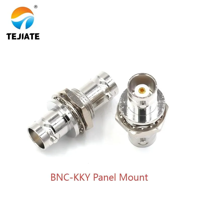
The image shows TEJTE BNC-KKY, a bulkhead panel-mount BNC connector for clean pass-through on instrument fronts or enclosures. It offers stable 50 Ω/75 Ω options, low mating loss, and reliable grounding for CCTV and RF benches.
Siamese cables combine a 75 Ω video line with a power pair — convenient for CCTV, but tricky when distances grow.
A good all-in-one bnc video cable needs three things: stable impedance, decent copper cross-section for voltage drop, and tight bonding between the video and power jackets to block water ingress.
In TEJTE’s lab tests, a 20 m Siamese run with 0.5 mm² power wire drops only ≈ 0.4 V at 12 VDC / 0.5 A load. Beyond 50 m, the same wire loses > 1 V, enough to dim camera IRs.
| Distance (m) | Wire Gauge (mm²) | Voltage Drop (V) | Video Loss (dB) | Recommendation |
|---|---|---|---|---|
| 20 | 0.5 | 0.4 | 0.5 | Safe |
| 50 | 0.5 | 1.1 | 1.2 | Add local power |
| 100 | 0.75 | 1.5 | 2.4 | Use separate power feed |
When assembling, use matching BNC-KKY couplers and ensure both power and video share a single ground reference — that’s what prevents hum bars on analog feeds.
If your installation runs outdoors, choose a bonded or “molded-pair” jacket rather than two loose cables tied together; it resists capillary water seepage.
The BNC-KKY panel mount types listed in TEJTE’s product catalog are ideal for connecting these dual lines through junction boxes or DVR housings — keeping the video path 75 Ω pure while grounding the power side solidly.
How do you verify loss and reflections after extending the line?
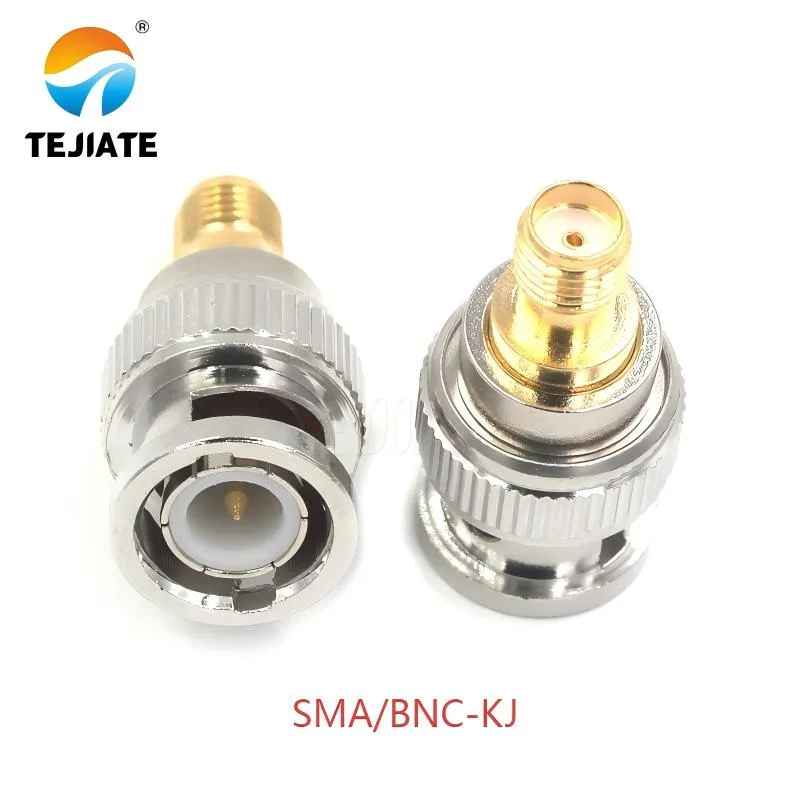
The product image shows TEJTE SMA/BNC-KJ, used to bridge SMA-F modules or pigtails to BNC-M instruments. Precision machining ensures low insertion loss and consistent 50 Ω matching across common bench frequencies.
Before calling a project done, always check the extension itself.
A quick continuity test tells you if the core and shield are intact, but to really trust a bnc extension cable, you need to measure its reflection behavior.
Start with DC continuity: both center and shield should read < 1 Ω end-to-end.
Then, using a simple return-loss bridge or VNA, sweep the cable at operating frequency.
Look for return loss (RL) better than –20 dB (≈ VSWR ≤ 1.22) for RF paths, or –14 dB for video lines.
| Check Item | Method | Accept Limit | Tools |
|---|---|---|---|
| Continuity | Multimeter (2-wire) | ≤ 1 Ω | DMM |
| Shield Integrity | Wiggle test | No drops | Scope / Beeper |
| Return Loss (50 Ω) | S11 @ 100 MHz – 1 GHz | ≥ ‑20 dB | VNA / RL bridge |
| Return Loss (75 Ω) | S11 @ 10 MHz – 500 MHz | ≥ ‑14 dB | Sweep tester |
| Insertion Loss | Compare end-to-end | ≤ 1 dB | RF meter / analyzer |
Field engineers often keep a log sheet with cable length, type, and RL value — especially for multi-channel systems.
That log becomes gold later when diagnosing noise spikes or image dropouts.
If you want a practical step-by-step of these tests, TEJTE’s SMA-to-BNC Adapter Lab Integration Guide shows how to run the same checks on mixed connectors and measure reflections accurately.
Could brand-level tolerance and plating change long-term stability?
Every cable looks identical when it’s new, but the difference shows up a year later—right after the first round of humidity and repeated plug cycles.
That’s where brand-level quality and plating consistency start to matter.
TEJTE’s BNC-JB3 connectors use a brass body with tri-alloy plating, rated for ≥ 500 mating cycles and a contact resistance ≤ 1.5 mΩ (center), ≤ 1 mΩ (outer).
Those numbers seem small, yet even a 1 mΩ jump at the interface adds micro-voltage offsets and tiny phase noise at higher frequencies.
Low-grade couplers often skip uniform plating or proper nickel under-layers.
That leads to micro-corrosion between the brass pin and PTFE insulator, increasing VSWR drift over time.
If your setup lives in a humid workshop or outdoor rack, nickel or tri-metal plating simply lasts longer.
| Parameter | TEJTE BNC-JB3 | Generic Low-Cost Connector |
|---|---|---|
| Contact Resistance (center / outer) | ≤ 1.5 mΩ / ≤ 1 mΩ | 3-5 mΩ typical |
| Mating Durability | ≥ 500 cycles | 100-200 cycles |
| Temperature Range | -45 °C ~ +125 °C | -20 °C ~ +85 °C |
| Dielectric | PTFE | PVC or Nylon |
| Compliance | RoHS / IEC 60169-8 | Often unlisted |
You don’t need enterprise software—just a clear labeling habit.
Every bnc extension cable that leaves the bench should carry three markings: impedance, length, and install date.
It sounds trivial until you’re standing on a ladder wondering which line runs to which camera.
Use a heat-shrink label near the connector or wrap a clear adhesive tag on the jacket.
Mark “50 Ω / RG58 / 5 m – 2025-11” or “75 Ω / RG59 / 20 m – Lobby Camera.”
Include an entry in a small spreadsheet listing S/N, measured IL, and return-loss values.
Can you document extensions so field maintenance is painless?
Even the braid density of the coax plays a role.
TEJTE’s RG58 double-shield uses a single-sided aluminum foil + 16 × 0.12 mm CCA braid, delivering around 90 dB shielding attenuation and VSWR ≤ 1.20 up to 3 GHz—tight tolerances that keep lab signals clean.
For test environments, these small details translate into fewer recalibrations and stable readings.
A few cents saved on plating today can cost hours of retesting later.
| Record Field | Example Entry |
|---|---|
| Cable Type / Impedance | RG58 - 50 Ω |
| Length | 5 m |
| Connector Model | BNC-JB3 |
| IL @ 100 MHz | 0.45 dB |
| RL @ 1 GHz | -22 dB |
| Install Date | 2025-11-05 |
| Location | RF Bench #2 |
Later, if a signal channel fails, your maintenance crew can check the label, open the log, and swap the correct jumper without tracing every line.
That’s the kind of discipline that makes a technical system “self-documenting”—and it’s exactly how TEJTE manages its own lab networks.
FAQ — Practical Questions on BNC Extension Cables
What size conduit should I choose for a BNC extension cable?
Stay below a 40 % fill ratio by area and maintain a bend radius ≥ 10 × OD.
A 16 mm conduit fits a single RG59 comfortably, leaving clearance for pull lubricant and heat expansion.
What is a good jacket thickness for outdoor BNC extensions?
Look for UV-resistant PVC or FEP jackets around 5–6 mm OD.
Thicker doesn’t always mean stronger—balance abrasion protection with bend flexibility.
What should I look for in a Siamese BNC video + power cable?
Use consistent 75 Ω video coax, adequate copper gauge for power, and bonded jackets.
Keep voltage drop below 1 V across the run to avoid IR-LED dimming.
How far can I run RG59 before video quality degrades?
With attenuation ≈ 4.5 dB / 100 m @ 100 MHz, you can safely reach 250–300 m for analog CCTV before brightness fade becomes visible.
Can I use a BNC coupler instead of buying a longer cable?
You can, but each joint adds ≈ 0.1 dB loss and reflection points.
A single bnc to bnc cable cut to length is cleaner for precision setups.
Do I need 50 Ω or 75 Ω for my extension?
Match your system—lab gear = 50 Ω, CCTV = 75 Ω—and keep the entire chain consistent to avoid return-loss jumps.
How do I verify the extension after installation?
Run a quick continuity test (< 1 Ω), then measure return loss ≥ –20 dB for RF or –14 dB for video using a sweep tester or VNA.
Closing Notes
Across this guide, you’ve seen how bnc extension cables behave across different lengths, impedances, and environments.
By combining low-loss coax such as RG58, RG59, or LMR-240 with quality connectors like TEJTE BNC-JB3, you maintain clean, reliable signals for years.
Keep impedance pure, label clearly, and log your test data—the small details that make an engineer’s setup both elegant and bulletproof.
Bonfon Office Building, Longgang District, Shenzhen City, Guangdong Province, China

A China-based OEM/ODM RF communications supplier
Table of Contents
Owning your OEM/ODM/Private Label for Electronic Devices andComponents is now easier than ever.
