BNC Bulkhead Connector Guide – Panel Mount, Cable Prep & Testing Tips
Nov 3,2025
Preface
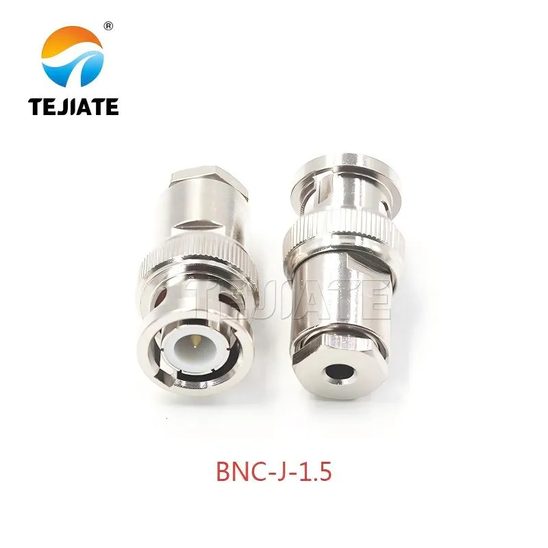
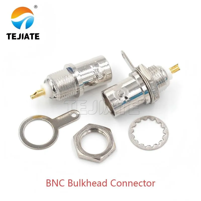
Figure is located in the preface, serving as the visual introduction to the document. It shows the actual appearance of this classic connector, whose design balances easy installation, mechanical stability, and consistent grounding performance.
Every engineer has faced it: a panel that’s ready for wiring, yet the connector just won’t seat right. The BNC bulkhead connector seems trivial until a small mismatch in thread length or washer stack throws off grounding or alignment. It’s the kind of detail that separates a clean install from a noisy one.
The BNC-J-1.5 open-window version from TEJTE hits that sweet balance. Its 14.8 mm threaded barrel mates perfectly with panels between 1 mm and 2 mm thick, locking firm without crushing gaskets. That consistency matters when you’re wiring measurement instruments or compact communication enclosures where every millimeter counts.
People often underestimate these connectors. Once you’ve fought with stripped nuts or loose shells under vibration, you start respecting the geometry behind a good panel-mount BNC.
Which BNC bulkhead fits your panel thickness?
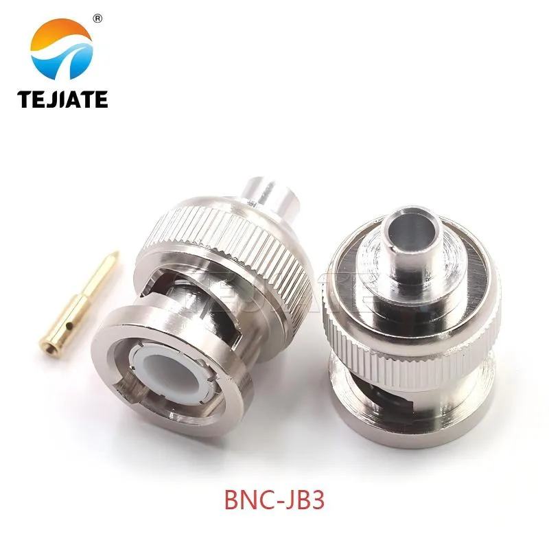
Figure is in the "Which BNC bulkhead fits your panel thickness?" section. Serving as a complement to the BNC-J-1.5, it visually presents a variant designed for thicker panels, expanding the reader's selection range.
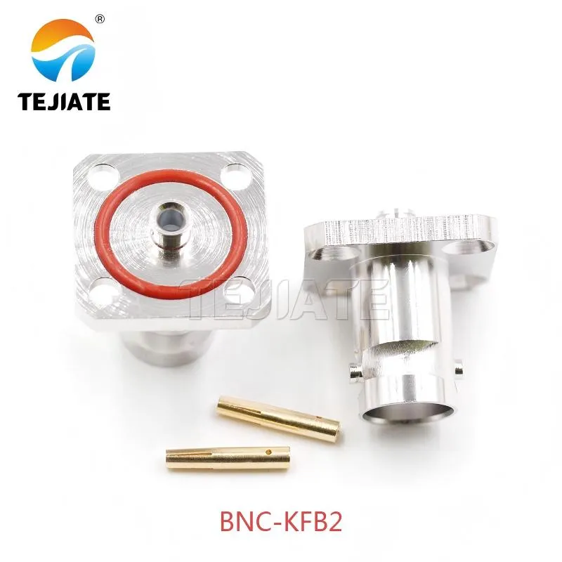
Figure also appears in the panel thickness selection section. It demonstrates the third mainstream form factor—the flange-mounted type. This connector addresses the critical needs of sealing and maintaining a stable connection in high-vibration environments through bolt fixation and O-ring compression.
Not all panels are made equal. Some are brushed aluminum barely 1 mm thick; others are multi-layer housings with powder coating that steals half a millimeter. When choosing a BNC bulkhead connector, look beyond the catalog code—think in terms of thread reach and how much of it remains after washers and paint.
For most light-gauge panels, the BNC-J-1.5 works beautifully: 14.8 mm thread, 9.5 mm body diameter, safe engagement when paired with a 0.3 mm lock washer and 0.5 mm gasket. If your wall is thicker than 2 mm, a long-thread BNC-JB3 (≈ 20.6 mm overall) or a flanged BNC-KFB2 with its O-ring seal may be the smarter pick—especially for outdoor or ruggedized enclosures.
Field note: Try to keep at least 80 % of the nut’s thread in contact. Less than that, and vibration will eventually loosen the joint even if torque looks right on paper.
Thread length vs. panel stack: nut, lock washer, gasket
Common stack values engineers actually measure in the field:
- Panel thickness (t): 1.2 mm
- Washer (w): 0.3 mm
- Gasket (g): 0.5 mm (optional)
- Nut (n): 2.5 mm
Then check:
Protrusion = L – (t + w + g)
For L = 14.8 mm → 13 mm left → passes the ≥ n × 0.8 engagement rule.
Straight vs. right-angle body for enclosure clearance
What panel cutout and hardware stack do you need?
| Parameter | Symbol | Range | Example (TEJTE BNC-J-1.5) | Note |
|---|---|---|---|---|
| Panel Thickness | t | 0.8 – 2.0 mm | 1.2 mm | Front wall or chassis |
| Hole Diameter | d | 9.3 – 9.7 mm | 9.5 mm | Laser or CNC cut |
| Thread Length | L | 11 – 15 mm | 14.8 mm | Connector barrel |
| Nut Thickness | n | ≈2.5 mm | 2.5 mm | Nickel-plated brass |
| Washer | w | ≈ 0.3 mm | 0.3 mm | Lock washer |
| Gasket | g | 0 – 0.5 mm | 0.5 mm | Silicone ring |
| Result | Protrusion = L – (t + w + g) = 13 mm | OK (≥ n × 0.8) | Check thread exposure |
Before mounting, clean the paint or anodization around the hole—oxidized surfaces weaken RF grounding.
For outdoor boxes, add a thin conductive washer; it preserves shielding while maintaining IP protection.
More design details appear in TEJTE’s Coaxial Cable Guide where panel transitions are discussed alongside cable loss and grounding continuity.
How to match 50 Ω or 75 Ω for your signal path?
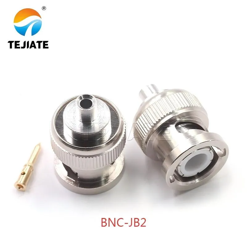
Figure is located in the "How to match 50 Ω or 75 Ω for your signal path?" section. It visually illustrates the core concept of impedance matching and introduces high-performance connectors like the BNC-JB2 that comply with the IEC 60169-8 standard.
A mismatch that looks harmless on the bench can eat half your return-loss margin at 3 GHz. The BNC series exists in both 50 Ω and 75 Ω forms—mechanically identical, electrically very different.
- 50 Ω paths: RF test gear, wireless modules, and network analyzers.
- 75 Ω paths: Video distribution and CCTV backbones.
The BNC-JB2 and BNC-JB3 models are built for DC–6 GHz, using PTFE insulators and ≤ 1.5 mΩ center-contact resistance. Rated from −45 °C to +125 °C and fully RoHS compliant, they meet IEC 60169-8 standards. The flanged BNC-KFB2 adds O-ring sealing for IP applications—common in outdoor sensors or 5G edge devices.
Mixing risks & mitigation
Yes, a 50 Ω plug fits a 75 Ω jack physically. Electrically? Not great. The mismatch adds a small reflection (~2–3 %). To cope:
- Keep the transition short (< 30 cm)
- Use a matching adapter when possible
- Don’t chain multiple mismatched joints
Return-loss budget thinking
Following the impedance discussion, Figure emphasizes a often-overlooked issue through a schematic: even if a single connector performs well, cascading multiple connectors can significantly degrade system performance, thus stressing the importance of consistent impedance at the system design level.
How do you prep RG58 or RG316 for crimp or solder?
Cable prep is where most signal losses are born. A BNC bulkhead connector can only perform as well as its termination. Whether you’re using RG58, RG174, or RG316, a clean strip with no nicked braid or uneven dielectric matters more than brand or plating.
Engineers usually keep two sets of tooling: a coax stripper with precise blade depth and a crimp die matched to the ferrule’s ID. For solder pins, temperature control and quick wetting are key — too much heat and PTFE insulation will creep.
Below is a verified reference drawn from TEJTE’s RG-series coax specs and production tooling.
| Cable Type | Outer Jacket Strip | Braid Strip | Dielectric Strip | Center Pin Type | Ferrule ID (mm) | Recommended Tooling |
|---|---|---|---|---|---|---|
| RG58 (50 Ω) | 5.0 mm | 3.0 mm | 1.5 mm | Crimp / Solder | 2.8 – 3.0 | Crimp Tool 0.178 die |
| RG174 (50 Ω) | 4.5 mm | 2.5 mm | 1.2 mm | Crimp | 2.3 – 2.4 | Micro Crimp Tool 0.128 die |
| RG316 (50 Ω) | 5.0 mm | 3.0 mm | 1.0 mm | Crimp / Solder | 2.4 – 2.5 | Precision PTFE Coax Crimp |
Workshop tip: If you hear a “snap” when seating the center pin, it’s right. If it slides loosely, the dielectric was shaved too far. Always pull-test before crimping the ferrule.
When assembling RG316 jumpers for high-frequency test leads (up to 6 GHz), keep the braid neat and tinned only if absolutely required. TEJTE’s own guide on Coaxial Cable Assembly and Testing explains why over-tinned braid increases VSWR above 2 GHz.
How do you install a BNC bulkhead step by step?
Installation seems trivial, but skipping torque order or washer sequence leads to intermittent grounds. Below is a field-tested workflow that balances mechanical stability and RF consistency.
- Verify cutout and hardware – Ensure the hole is 9.5 ± 0.2 mm and de-burred. Dry-fit the connector to confirm alignment.
- Terminate center pin – Crimp or solder the pin to the prepared center conductor. Avoid wicking solder into the dielectric.
- Seat dielectric and braid – Slide the pin into the body until it clicks; fold braid evenly around the shell.
- Slide ferrule and crimp – Crimp evenly without flattening the body; ferrule should sit flush with the shell.
- Insert body into panel – Align the key, add washer and nut, then finger-tighten before final torque.
- Tighten to spec – Use controlled torque (~ 0.5 N·m for brass body). Stop once the washer bites; don’t over-stress the threads.
- Bonding check – Use a multimeter: shell to panel < 0.1 Ω means solid ground.
This step-wise method mirrors what TEJTE follows during quality validation. Each connector is tested for contact resistance < 1.5 mΩ (center) and insulation resistance > 2000 MΩ per IEC 60169-8.
Can you keep bend radius and strain relief within spec?
Good coax handling is half of RF reliability. Bending a BNC cable assembly too close to the back shell adds hidden reflection and weakens the crimp joint.
Typical minimum bend radii:
- RG58: ≥ 50 mm
- RG174: ≥ 28 mm
- RG316: ≥ 15 mm
If space is tight inside an enclosure, use a short pigtail jumper between the panel bulkhead and the main harness. For instance, a 5 cm RG316 pigtail relieves stress while preserving return-loss below −20 dB at 3 GHz.
Right-angle bulkheads help where clearance is under 25 mm. However, for long test leads or flexible setups, straight connectors with strain-relief sleeves maintain impedance more uniformly. When planning harnesses, reference TEJTE’s RF Cable and Connector Selection Guide for compatible assemblies across RG58, RG174, and RG316 ranges.
How to test continuity and return loss after assembly?
DC checks: shield continuity and isolation
Start simple:
- Shell-to-panel continuity: should read < 0.1 Ω. Anything higher hints at poor washer contact or trapped paint.
- Center pin-to-shield isolation: > 100 MΩ (for 50 V DC range) ensures the dielectric isn’t heat-damaged.
A handheld LCR meter or a standard multimeter works fine here. In field labs, engineers often log these readings next to serial numbers—an easy way to trace assembly quality.
Simple S11 “smoke test”
For RF verification, connect a short, known-good coax (e.g., RG316, 15 cm) to a network analyzer or return-loss bridge.
- Terminate the opposite end in 50 Ω load.
- Sweep DC–3 GHz (or up to 6 GHz for precision models like BNC-JB3).
- Look for |S11| < −20 dB across the band.
If a reflection spike appears around 1 GHz, it usually means a slight crimp void or center-pin gap. TEJTE’s QA method includes a “5-cycle remate test” — measuring insertion loss before and after five connect/disconnects to ensure mechanical consistency.
Quick insight: return-loss dips rarely come from the connector itself. Most arise from braid fray, poor grounding, or excessive solder wicking inside the dielectric.
How do you seal outdoor installs against moisture?
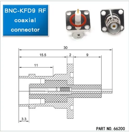
Figure is in the "How do you seal outdoor installs against moisture?" section. As a concrete example, it shows how to use an engineering drawing to accurately understand the physical interface and mounting requirements of a connector, which is crucial for ensuring sealing and proper installation.
Gasket and O-ring compression
Thread seal and drip loop
For straight-body connectors, apply a thin wrap of PTFE thread tape around the rear nut. Avoid thick sealant; it can block electrical bonding.
Cables exiting downward should form a drip loop—a small bend lower than the connector port—to prevent water from creeping toward the shell.
UV and temperature concerns
PVC-jacketed cables like RG58 handle temperatures up to 70 °C but degrade under UV. For constant sun exposure, switch to FEP-jacketed RG316, rated −55 to +150 °C with minimal dielectric drift.
These combinations, detailed further in TEJTE’s Outdoor RF Assembly Guide, extend service life far beyond standard builds.
Avoid these fit and noise mistakes during panel mount
Paint under ground path
Oversized holes
Braid whiskers and cross-threading
Tiny braid strands touching the center pin are a classic intermittent fault—especially on RG174. Use magnification if necessary during assembly.
Cross-threaded nuts should be replaced, not “forced straight,” since brass deforms easily and affects torque calibration.
Speed up ordering with the connector–cable matrix
| Mount Type | Impedance (Ω) | Cable Compatibility | Termination | Body Form | Panel Thickness Range (mm) | Notes |
|---|---|---|---|---|---|---|
| BNC-J-1.5 | 50 | RG316 / RG174 | Crimp / Solder | Straight | 1 – 2 | General lab and chassis use |
| BNC-JB2 | 50 | RG58 | Solder | Straight | 1 – 2 | High-power lab signals up to 6 GHz |
| BNC-JB3 | 50 | RG58 | Solder | Straight | 2 – 3 | Extended-thread for thicker panels |
| BNC-KFB2 | 50 | RG405 | Solder | Flange | 1 – 3 | IP67 O-ring sealed outdoor version |
Frequently Asked Questions (FAQ)
1. Can a 50-ohm BNC plug connect to a 75-ohm bulkhead jack?
2. What size hole should I drill for a BNC panel mount connector?
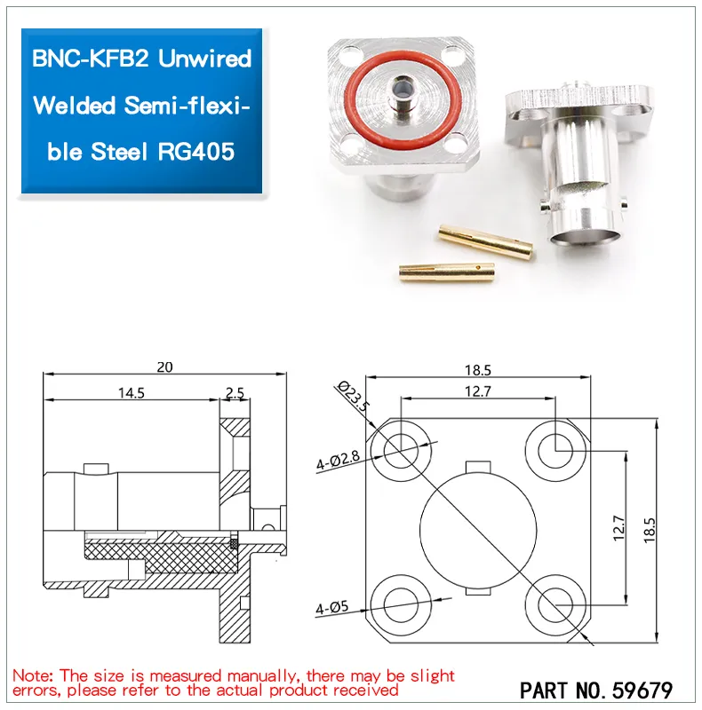
Figure serves as a key visual reference in the document for understanding flanged and sealed connectors like the BNC-KFB2. Through an exploded view, it visually reveals how this model achieves moisture-proof sealing via the integrated O-ring, and ensures mechanical stability and effective grounding in outdoor or harsh environments through the flange and thread structure, materializing the "O-ring seal" and "flange mount" features described in the text.
3. Is crimping or soldering better for RG58 and RG316 cables?
Both methods work when done properly.
- Crimp terminations are faster, repeatable, and ideal for production.
- Solder joints allow more control on small batches or when thermal cycling is expected.
For RG316 (with PTFE dielectric), avoid prolonged soldering heat. If you prefer consistent impedance and speed, use crimp ferrules matched to 2.5 mm ID.
4. How tight should I torque the BNC bulkhead nut?
5. Can I mount a BNC connector on a painted or plastic enclosure?
6. How should I weather-seal outdoor BNC panel feed-throughs?
Use the supplied silicone gasket or O-ring and compress evenly. For long-term exposure, wrap the joint with self-fusing tape and form a drip loop in the cable.
PVC-jacketed RG58 works in mild conditions, but for full-sun or high-temperature sites, switch to FEP-jacketed RG316 rated up to 150 °C.
TEJTE’s Outdoor Connector Sealing Guide covers detailed sealing and grounding examples.
Safety & Compliance Note
Even the most solid-looking BNC bulkhead connector is only as reliable as its compliance behind the scenes. All TEJTE parts conform to IEC 60169-8 dimensional standards and meet RoHS 3 and REACH environmental directives. These aren’t just checkboxes — they ensure mechanical interchangeability across global test equipment and protect long-term material stability.
For high-stress fields such as defense electronics or automotive telematics, it’s worth requesting material traceability and salt-spray certification when placing your order. Those small paperwork steps can save an entire qualification round later.
Before powering up any RF system, take a moment to verify the grounding path from connector shell to chassis. A quick continuity check—five seconds at most—can prevent hours of chasing phantom noise or unstable readings during panel-mount RF testing. Seasoned engineers do it out of habit; newcomers soon learn why.
Bonfon Office Building, Longgang District, Shenzhen City, Guangdong Province, China

A China-based OEM/ODM RF communications supplier
Table of Contents
Owning your OEM/ODM/Private Label for Electronic Devices andComponents is now easier than ever.
