
A blade fuse holder can look correct in a product photo and still be wrong for the circuit.
That mistake usually starts with the fuse shape. A buyer sees a “car fuse holder,” confirms the ampere number, and assumes the part will fit. The sample may even pass a simple continuity check. The problem appears later, after the fuse runs warm, the terminal loses grip, or the maintenance team discovers that a MINI blade fuse was never meant to sit in a standard holder slot.
A good selection process starts with the exact blade format, then checks current, voltage, contact construction, mounting style, and environment. That is the only way to keep a blade fuse holder from becoming the weak point in an otherwise simple low-voltage protection circuit.
How do you identify the blade format before choosing a holder?
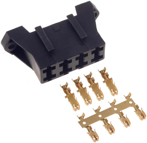
This image displays the internal structure of an ATO ATC blade fuse holder, including metal terminal contacts and housing design. Proper contact force and terminal construction help improve current carrying capability and long-term electrical reliability.
Start with geometry. Fuse color can help identify ampere rating inside a known fuse family, but it does not prove holder compatibility.
A red fuse may be 10 A, but the holder still needs the correct blade width, blade spacing, body size, insertion depth, and retention design. If those details are not checked, the fuse may sit loosely, only partly contact the terminal, or fail under vibration.
For purchasing, avoid descriptions like:
“Normal automotive fuse holder, 20 A.”
That is too vague. A better request is:
“Standard ATO/ATC blade fuse holder for approved fuse P/N, rated system voltage, required continuous current, mounting style, and environmental condition.”
Current automotive blade-fuse families are not one universal mechanical system. Standard ATC/ATO, MINI, low-profile MINI, Micro, and MAXI products all need their own holder path. Treating them as interchangeable sizes is one of the easiest ways to create a hidden field failure.
Use a simple identification card before approving the holder.
| Check Item | Required Information | Status |
| Fuse family | Standard, MINI, Micro, MAXI, or other defined family | PASS / HOLD |
| Blade width | Confirm from fuse drawing | PASS / HOLD |
| Blade spacing | Confirm from fuse drawing | PASS / HOLD |
| Body width and height | Confirm holder clearance | PASS / HOLD |
| Fuse current rating | Marking plus datasheet | PASS / HOLD |
| Fuse voltage rating | Exact P/N rating | PASS / HOLD |
| Holder P/N | Exact supplier drawing | PASS / HOLD |
| Approved mate | Fuse and holder confirmed together | PASS / HOLD |
This table is simple on purpose. It catches the basic mistake before the discussion moves into current rating or price.
For broader holder architecture decisions, this blade-format check should sit under the parent selection process in your Fuse Holder Selection Guide. The blade version is only one branch of the full fuse-holder decision.
Which ATO/ATC holder details must match the fuse?
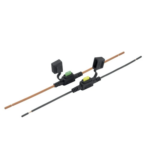
This image shows an inline blade fuse holder used in automotive and DC electrical circuits. The holder integrates fuse protection into wire harness applications and provides a compact solution for protecting individual power branches.
ATO and ATC are often discussed together in the market, but the label alone is not enough for approval.
A supplier may list a product as an ATO fuse holder, ATC fuse holder, or ATO ATC fuse holder. That does not automatically confirm the terminal design, contact force, material, plating, or continuous-current capability. The exact datasheet still matters.
The visible slot is only the front of the problem. Behind it, the holder has a spring contact system that must grip the fuse blades with enough force and enough contact area. If that system is weak, the fuse can remain electrically connected while the holder runs hot.
A standard blade fuse holder should be checked in two separate ways:
| Approval Point | Fuse Side | Holder Side |
| Physical interface | Blade dimensions | Slot and terminal geometry |
| Electrical rating | Fuse current and voltage | Holder continuous current and voltage |
| Thermal behavior | Time-current behavior | Contact heating and housing limit |
| Mechanical retention | Blade stiffness | Terminal spring force |
| Service life | Replacement cycles | Contact wear and retention loss |
Do not merge fuse rating and holder rating into one number. A fuse marked 30 A does not prove the holder can carry 30 A continuously in the actual installation. That depends on terminal construction, wire or PCB connection, temperature rise, and airflow.
For RF buyers, this may feel similar to connector sourcing: the front interface can mate, but the rear construction still decides whether the part works in production. Fuse holders have the same kind of trap. The mating shape is not the whole specification.
How do MINI, Micro, Standard, and MAXI holder paths differ?
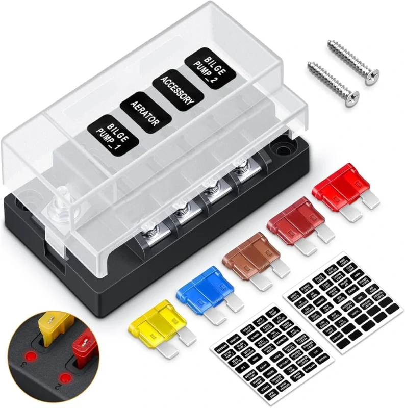
A mini fuse holder is not just a smaller standard holder. A mini blade fuse holder is a dedicated mechanical system for miniature blade fuses. The same rule applies to Micro and MAXI formats.
MINI is often used where space is tight. Micro formats are even more compact and common in dense vehicle electrical designs. Standard ATO/ATC remains the middle-size reference for many automotive and accessory circuits. MAXI is the larger, higher-current boundary, but it should not be used as a casual upgrade just because a smaller holder overheated.
Overheating is a symptom. It may be caused by undersized wire, poor crimping, low contact force, wrong terminal material, high ambient temperature, or incorrect holder selection. Moving to a maxi blade fuse holder without diagnosing the original problem can hide the real issue.
A practical comparison looks like this:
| Blade Family | Relative Size | Dedicated Holder Needed? | Main Selection Risk |
| Micro | Smallest group | Yes | Confusing it with MINI |
| MINI | Compact | Yes | Assuming it fits standard holders |
| Standard ATO/ATC | Medium | Yes | Assuming all holders carry the same current |
| MAXI | Large | Yes | Ignoring terminal and thermal design |
Use exact current ranges only from the selected fuse and holder documentation. The family name helps narrow the path, but the final approval still belongs to the part number.
When should current rating force a different blade format?
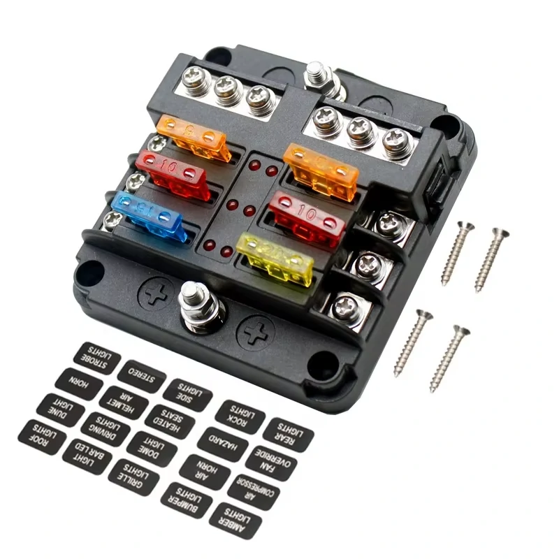
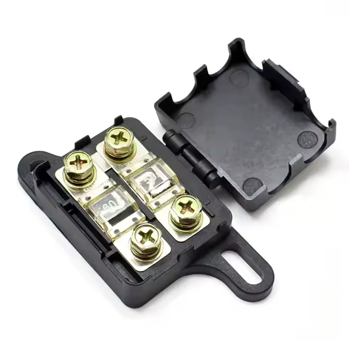
This image shows a multi-position automotive blade fuse block designed for centralized circuit protection. Fuse blocks are commonly used when multiple electrical branches require independent fuse protection in automotive and DC power systems.
Do not choose the blade format from ampere rating alone.
The better design order is:
Load → conductor → protection requirement → fuse family → holder
The weaker order is:
Load current → same-number fuse holder
That second path is where many purchasing mistakes come from. A buyer asks for a 30A blade fuse holder, receives a holder that physically accepts a 30 A fuse, and assumes the job is done. But continuous holder current, maximum holder current, fuse opening behavior, terminal temperature, and wire capacity are different checks.
As current increases, small contact problems become expensive quickly. Contact resistance that looks minor at low current can create serious local heating at higher current.
Use the basic heat relationship:
Pheat = I² × R
That square matters. If current doubles, heating from the same resistance rises four times. This is why a holder can brown, soften, or lose spring force even when the fuse has not blown.
A blade format escalation gate keeps this decision controlled:
- Define normal continuous current.
- Define transient or inrush current.
- Confirm conductor capacity.
- Confirm holder continuous rating.
- Confirm loaded temperature.
- Confirm fuse time-current behavior.
- Move to a larger validated format only if the complete system requires it.
Decision result:
Standard / MINI adequate → retain format
Current or thermal margin inadequate → evaluate larger validated format
This is also where single-circuit holder selection should be separated from multi-circuit distribution. If several circuits share one protected location, that may belong in a future Automotive Fuse Block Selection Guide, not inside a single blade holder decision.
How should a 12V automotive circuit constrain holder selection?
This image shows a blade fuse holder with internal contact terminals. The terminal structure, contact pressure, and material selection directly affect resistance, temperature rise, and electrical performance during continuous operation.
A 12V blade fuse holder is not approved just because the vehicle is called a 12 V system.
A running vehicle does not stay at exactly 12.0 V. Charging voltage, transient events, battery condition, accessory loads, and wiring layout all affect the electrical environment. The holder does not need to “make” the system 12 V. It needs to survive the actual DC voltage, current, temperature, vibration, and service conditions around that circuit.
For an automotive blade fuse holder, check the maximum DC voltage from the exact part number. Many automotive blade fuse and holder products are commonly specified around 32 VDC systems, but that number should come from the holder documentation, not from a marketplace title.
Do not let voltage rating distract from the rest of the chain. The holder is only one part of the protection path:
| Protection Element | What Must Be Checked |
| Vehicle circuit | Nominal and maximum normal voltage |
| Fuse | Voltage rating, current rating, time-current behavior |
| Holder | Voltage rating, continuous current, contact system |
| Wire | Gauge, insulation, routing temperature |
| Terminal | Crimp quality, material, retention |
| Environment | Moisture, dust, vibration, heat |
A valid low-voltage circuit needs all of these to match. A good fuse in a weak holder is still a weak protection point.
Also keep transient protection outside the holder’s job description. A blade holder does not replace TVS protection, load-dump design, reverse-polarity protection, or ECU-level qualification. It simply provides the mechanical and electrical interface for the fuse.
When does waterproofing become a holder requirement?
A rubber cap is not a waterproof rating.
That point matters because many low-cost blade fuse holders look sealed in photos. A cap may block casual dust or splash, but it does not automatically mean IP67, engine-bay suitable, dust-tight, or acceptable for exterior wiring.
Before specifying a waterproof blade fuse holder, define the installation zone:
| Installation Zone | Typical Exposure | Holder Requirement |
| Interior electronics | Low moisture, low dust | Standard holder may be enough |
| Trunk or cargo area | Occasional moisture, vibration | Covered or protected holder |
| Engine bay | Heat, vibration, splash, contaminants | Rated sealed holder, material check |
| Exterior accessory wiring | Water spray, dust, movement | Explicit environmental rating |
| Off-road or marine-adjacent use | Heavy splash, mud, corrosion risk | Higher sealing and retention review |
The weak point is often not the cap. Leakage can enter from the wire exit, terminal entry, cover fit, housing joint, or service opening. If the holder is inline, the splice and wire seal may matter as much as the fuse cover.
For full wire-in, wire-out design, that topic belongs in the Inline Fuse Holder Selection Guide. This blade holder article should only define when sealed blade construction becomes necessary, not repeat the full harness sealing process.
A useful purchasing sentence is:
“Waterproof blade fuse holder for [fuse family], rated current, system voltage, wire size, installation zone, and required IP/environmental rating.”
That is much safer than:
“Waterproof car fuse holder.”
Choose the mounting architecture before the terminal style
The mounting architecture decides how the fuse will be installed, serviced, and inspected. Terminal style comes after that.
If the fuse protects one harness branch, inline mounting is often the natural path. It keeps the protection close to the wire branch and can be serviced without opening an electronic enclosure. But inline holders bring wire gauge, splice, strain relief, and sealing questions. Those details should be handled before ordering.
If the fuse belongs inside an electronic assembly, PCB mounting may be cleaner. A PCB blade fuse holder can allow service access while keeping protection on the board. But PCB copper width, solder joint quality, heat rise, and enclosure temperature all become part of the current path.
Panel or stackable holders are different again. They may be useful when field access matters, but they need clearance planning. A fuse that can technically be inserted is not automatically easy to replace after the harness, cover, bracket, or adjacent module is installed.
A simple decision path helps:
| Selection Question | Direction |
| Is there only one protected circuit? | Use an individual blade fuse holder |
| Does it protect a wire-in/wire-out branch? | Consider inline architecture |
| Does protection belong inside a device? | Consider PCB mounting |
| Does the user need tool-free field access? | Check panel or service-facing design |
| Are several circuits grouped in one service location? | Evaluate a fuse block instead |
Multi-circuit distribution should not be forced into this article. If the requirement is centralized distribution, shared supply, multiple outputs, and one service panel, that is closer to an automotive fuse block or blade fuse block decision.
How do contact force and voltage drop reveal a weak holder?
A blade fuse holder can pass continuity and still be electrically poor.
Continuity only says the circuit is connected. It does not say the connection is low resistance under load, stable after heating, or strong after repeated fuse replacement.
The current path is:
Wire or PCB → holder terminal → fuse blade → fuse element → opposite blade → holder terminal → wire or PCB
Every interface adds resistance. If terminal force is weak, plating is poor, the fuse is not fully seated, or the holder has been serviced many times, resistance can rise. The symptom may be voltage drop, heat, discoloration, softened plastic, intermittent power, or nuisance faults in the protected circuit.
Use two simple checks:
Vdrop = I × R
Pheat = I² × R
Voltage drop affects the load. Local heating affects the holder.
This is why a holder may look fine at 2 A and fail at 20 A. The contact system is being tested harder, and heat rises quickly as current increases.
For a low-risk accessory circuit, a simple loaded voltage-drop check may be enough. For higher-current, high-temperature, or frequently serviced equipment, the holder should be checked before and after insertion cycles.
Do not ignore mechanical feel. A fuse that inserts with almost no resistance, rocks inside the slot, or loses retention after a few replacements deserves review, even if it still passes a meter test.
Use standards and drawings to approve dimensional compatibility
Old dimension charts are a risky basis for new purchasing specs.
For road-vehicle blade-type fuse-links, ISO lists ISO 8820-3:2026 as covering Type C medium, Type E high-current, and Type F miniature blade-type fuse-links for road vehicles (ISO). The practical takeaway is simple: use the current standard as a reference point, then verify the exact fuse and holder drawings.
The standard applies to the fuse-link. It does not approve every holder that claims to accept a similar blade shape.
A holder still needs its own:
- outline drawing
- terminal drawing
- continuous-current rating
- material specification
- environmental rating
- insertion and retention requirement
- production change-control record
A current fuse datasheet can help show why exact documentation matters. Littelfuse ATOF blade fuses, for example, are rated 32 VDC and state compliance with SAE J1284 and ISO 8820-3 in the published datasheet (Littelfuse ATOF datasheet). That statement belongs to that fuse series. It does not automatically approve an unknown holder, an unknown terminal, or a copied housing.
This record is not paperwork for its own sake. It protects the buyer when a supplier changes terminal plating, housing material, mold source, or spring geometry but keeps the same sales title.
How should first-article testing prove thermal and mechanical margin?
First-article testing should test the actual fuse and holder pair, not a similar sample.
Record the exact fuse family, fuse current, holder P/N, terminal style, wire size or PCB implementation, and installation position. Then test the pair under representative load. A bench continuity check is too light for a part that may sit near heat, vibration, and repeated service cycles.
Start with loaded voltage drop. Measure it cold, then after the holder reaches a stable warm condition. If the product will be serviced often, repeat the measurement after several insertion and removal cycles.
Next, measure temperature at the real hot spots:
| Test Point | Why It Matters |
| Fuse blade | Confirms blade-to-terminal heating |
| Holder terminal | Reveals weak contact or poor plating |
| Housing | Shows plastic heat exposure |
| Crimp or solder joint | Finds termination heat |
| PCB copper or wire entry | Checks current path beyond the holder |
A holder can stay electrically functional while the spring force declines. That is why retention should be checked after thermal cycling or repeated fuse replacement. Loose retention often appears before a complete open circuit.
If a holder fails here, do not solve it only by raising fuse size. The fuse protects the circuit. It does not repair contact resistance, wrong terminals, poor crimping, or undersized conductor design.
Build the RFQ and lot-control plan around the exact fuse family
A clear RFQ prevents most blade fuse holder mistakes before samples are made.
Write the fuse family before the ampere value. “Blade fuse holder, 20 A” is not enough. It leaves the supplier to guess the mechanical family, terminal style, voltage class, mounting method, and environment.
A stronger RFQ line is:
Standard ATO/ATC blade fuse holder for approved fuse P/N, 12 V automotive accessory circuit, required continuous current, wire-in/wire-out installation, covered interior mounting, voltage-drop limit to be confirmed by sample test.
For a higher-risk circuit, add temperature-rise limit, retention requirement, plating requirement, and sample test quantity.
Use separate fields for fuse current and holder current:
| RFQ Field | Requirement |
| Blade fuse family | ATO/ATC, MINI, Micro, MAXI, or exact family |
| Approved fuse P/N | Required |
| Fuse current range | Required |
| Holder continuous current | Required |
| Holder maximum current | Required |
| System voltage | Required |
| Mounting architecture | Inline, PCB, panel, or other |
| Terminal type | Crimp, solder, PCB, quick-connect, or specified |
| Contact material / plating | Required for controlled sourcing |
| Environmental requirement | Interior, engine bay, exterior, sealed, etc. |
| Waterproof rating | Only if explicitly needed |
| Voltage-drop limit | Define test current |
| Temperature-rise limit | Define location and condition |
| Drawing revision | Required |
| Production quantity | Required |
| Change-control rule | Required |
Incoming inspection should then check more than the carton label. Confirm the fuse family, holder P/N, critical dimensions, terminal condition, fuse seating, retention, continuity, and any agreed voltage-drop test. If a supplier changes terminal material, plating, tooling, housing resin, or spring geometry, increase inspection before releasing the lot.
That is especially important for blade fuse holders bought from multiple suppliers. Two parts can share the same appearance and still behave differently under load.
FAQ
Can a MINI blade fuse be installed in a standard blade fuse holder?
No. MINI and standard blade fuse families use different physical interfaces and need compatible holders. Do not approve the holder from fuse color, ampere rating, or product-photo appearance.
Are ATO and ATC fuse-holder labels always interchangeable?
Do not assume that from the name alone. Confirm blade dimensions, fuse P/N, holder P/N, terminal construction, and datasheet rating before treating an ATO fuse holder and ATC fuse holder as interchangeable in production.
Can every holder that physically accepts a 30A blade fuse carry 30A continuously?
No. A 30A blade fuse holder must be checked by holder continuous-current rating, terminal design, contact material, wire or PCB connection, ambient temperature, and loaded voltage drop.
Can a 32V-rated blade fuse holder be used in a nominal 12V automotive system?
Potentially, if the exact holder’s voltage, current, terminal, environmental, and fuse compatibility specifications meet the vehicle circuit. A 32 VDC rating does not mean the circuit operates at 32 V. It only describes part of the holder’s allowable electrical rating.
Does a rubber cover make a blade fuse holder waterproof?
No. A waterproof blade fuse holder should have an explicit environmental rating or supplier specification. Check the cap, housing joint, wire entry, terminal entry, and service opening.
Why can holder voltage drop increase after several fuse replacement cycles?
Repeated fuse insertion can reduce contact force, scratch plating, expose oxidation, or loosen the terminal grip. Higher contact resistance increases voltage drop and local heating.
Does ISO 8820-3:2026 mean all automotive blade fuse holders are interchangeable?
No. ISO 8820-3:2026 applies to blade-type road-vehicle fuse-links. The holder still needs its own drawing, terminal specification, current rating, material data, mounting design, and environmental approval.
Final practical note
The safest blade fuse holder selection does not start with price or ampere marking. It starts with the exact blade family, then verifies the holder terminal system, continuous current, voltage rating, mounting architecture, environment, and first-article test result.
For purchasing, the best short rule is:
Specify the fuse family, approved fuse P/N, holder P/N, continuous current, system voltage, mounting style, terminal construction, environmental requirement, and inspection method before releasing production.
That gives engineers, buyers, and suppliers the same target. It also prevents the most common blade holder failure: a part that fits the fuse, but not the job.
