
A replacement fuse box can look correct on the bench and still be wrong for the vehicle.
The connectors may plug in. The cover may snap shut. The fuse labels may even look close enough to pass a quick visual check. The trouble starts when one feed is routed differently, a relay cavity serves another function, or an interior accessory circuit gets confused with an engine-bay distribution path.
That is why an automotive fuse box should be treated as a vehicle-specific electrical center, not just a plastic box that holds blade fuses.
How do you locate the correct automotive fuse box before opening it?
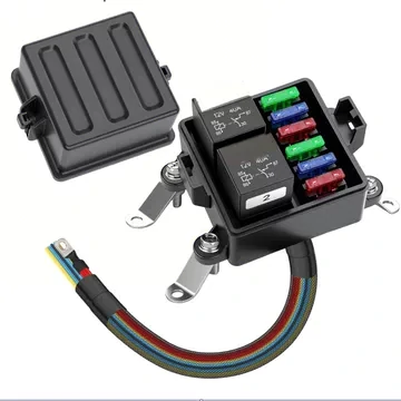
This image presents a compact automotive fuse and relay box designed for vehicle circuit protection. The unit includes blade fuse positions, relay sockets, metal mounting brackets and a color-coded harness for organized wiring.
Start with the vehicle information, not the box shape.
A car fuse box location can vary by make, model year, trim, powertrain, and market version. One vehicle may place a primary electrical center under the hood, another may split protection between the engine bay and cabin, and a higher-trim version may add a rear or trunk electrical center for body electronics.
Before removing covers or pulling components, record the vehicle identity:
- Make and model
- Model year
- Engine or powertrain option
- Fuse-box location
- Fuse-box part number
- Cover or lid part number
- Harness connector count
- Fuse and relay families present
This prevents a common service mistake: using a generic diagram for a similar vehicle and assuming it applies to the one in front of you.
Use the vehicle service information before relying on a generic location diagram
Online fuse-box diagrams can be helpful for orientation, but they should not be the final authority. A vehicle fuse box is tied to the harness, options, relay layout, and factory power-distribution design.
A technician or buyer should verify the actual service information before treating any cavity as correct. This matters even more when the vehicle has been repaired, modified, imported, or fitted with aftermarket accessories.
Keep OEM and added electrical centers separate during inspection
Not every enclosure with fuses is the factory automotive fuse box.
A vehicle may contain:
- OEM engine-bay fuse box
- Interior fuse box
- Added accessory fuse block
- Aftermarket relay box
- Trailer or auxiliary power-distribution module
For new accessory circuits, TEJTE’s Fuse Block Selection Guide is the better reference point than modifying the OEM box. The factory fuse box protects the original vehicle architecture; an auxiliary block is for added branches that need their own controlled protection.
Build an Automotive Fuse Box Identity Card
Use this simple record before ordering parts or beginning diagnosis.
This small record saves time later. If the box must be replaced, the part number, connector count, and fuse map are already tied to the exact vehicle.
Why can one vehicle have more than one fuse box?
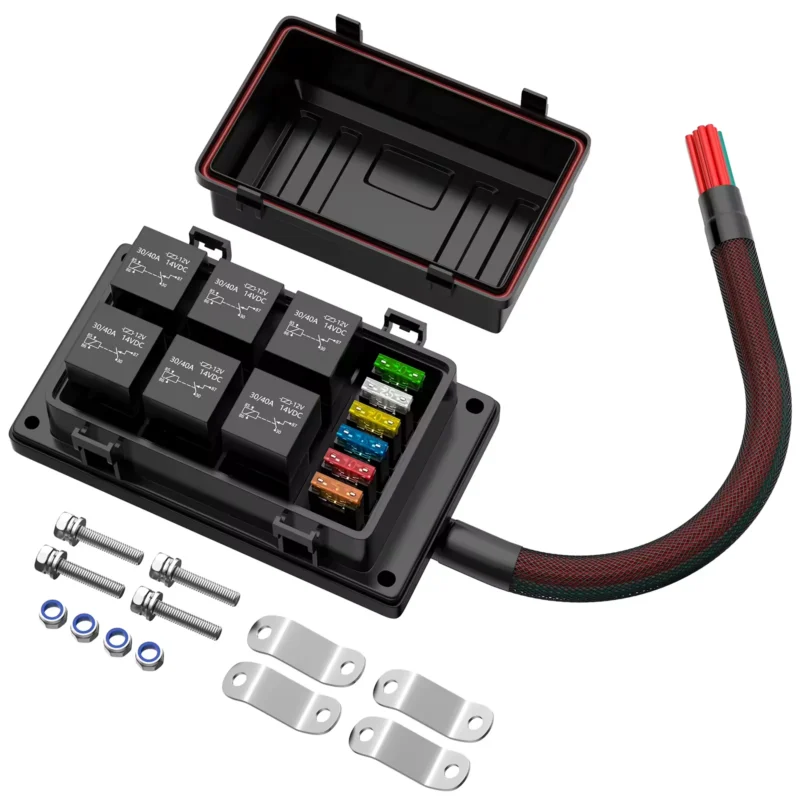
A single fuse box would be simple. Vehicle electrical systems are not always built that way.
Power may enter through a battery terminal or front distribution point, pass through high-current protection, and then branch toward engine, body, cabin, lighting, infotainment, trailer, or accessory loads. Splitting the electrical centers can reduce harness length, simplify assembly, isolate environments, and keep service access reasonable.
An engine bay fuse box often sits near the battery, alternator, cooling fans, ABS, starter-related feeds, or other high-current areas. An interior fuse box often supports body electronics, lighting, convenience functions, and lower-current accessory circuits. That is a pattern, not a universal rule.
Use the engine-bay box for location context, not a fixed function list
The phrase “engine bay fuse box” tells you where the box sits. It does not prove every circuit inside it.
Possible responsibilities include:
- Main power distribution
- Fan or motor circuit protection
- Powertrain-related relays
- ABS or chassis circuits
- High-current branch protection
- Under-hood accessory feeds
Heat, water, dirt, road salt, and vibration make this location more demanding. A waterproof automotive fuse box may need sealed covers, locked connectors, proper drainage, and materials that tolerate under-hood temperature swings.
Use the interior box for body and accessory context
An interior fuse box usually has a different service problem: access.
It may be behind a side panel, under the dashboard, near the glove box, or in a tight footwell. The risk is less about direct road splash and more about wrong probing, trim damage, poor visibility, and confusion between body-control circuits.
Do not probe random cavities to find switched power. If a new radio, lighting controller, or auxiliary device needs protection, the circuit should be engineered rather than borrowed from an unknown factory fuse position.
Create a Fuse Box Location & Role Matrix
| Location | Possible Role | Main Environmental Risk | Service Access |
| Engine bay | Main or high-current distribution | Heat, water, contamination | Medium |
| Cabin / interior | Body and accessory circuits | Access, labeling, accidental shorts | High |
| Trunk / rear | Rear accessories or modules | Moisture, hidden access | Medium |
| Added auxiliary area | Aftermarket loads | Installation-dependent | Variable |
Use the table as a starting point only. The actual fuse map and service data decide which box protects the circuit.
How do you read the fuse-box lid map without guessing at a circuit?
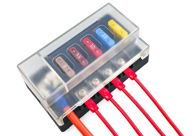
This image shows a compact automotive fuse block with a transparent protective cover, multiple blade fuses and connected red wires. It is suitable for explaining auxiliary circuit protection, fuse visibility and organized branch wiring.
A lid map is a guide, not a diagnosis.
Labels such as FAN, ECU, ACC, PWR, or HORN identify a circuit position, but they do not prove the load is faulty. They also do not describe every splice, relay contact, module input, or shared feed downstream of the fuse.
Before pulling several components, capture the map. A phone photo is often enough if it is clear, square, and includes the full legend. Record the cavity number, label, fuse rating, relay position, spare position, and any empty cavities.
Keep fuse rating and operating current separate
A 20 A fuse does not mean the circuit normally draws 20 A.
The fuse rating belongs to the protection design. Actual operating current depends on the load, wiring, duty cycle, and vehicle state. Upsizing a fuse because the original one opens repeatedly can remove protection from the wiring. The fault should be found instead.
For blade-style positions, verify both the ampere rating and the physical fuse family. Standard, MINI, Micro, and MAXI blade fuses are not interchangeable just because the color looks familiar. TEJTE’s Blade Fuse Holder Selection Guide is useful when the issue is blade format, terminal fit, and thermal contact quality rather than the full vehicle fuse-box assembly.
This sheet is especially helpful when diagnosing an intermittent fault. If a relay or fuse is moved during inspection, the original position can still be restored.
Which clues separate a fuse socket from a relay socket or spare cavity?
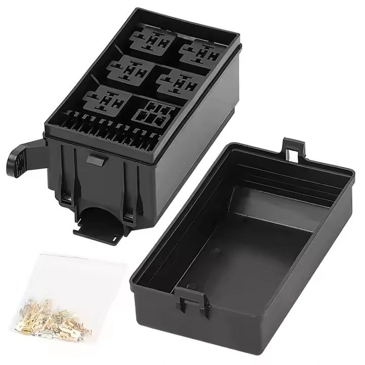
This image displays an empty automotive fuse relay box housing with its protective cover and loose metal terminals. It is useful for showing fuse box structure, relay cavity layout and custom harness assembly components.
A fuse-and-relay box can contain more than blade fuses. It may also include relay sockets, circuit-breaker positions, diode positions, unused cavities, and option-specific spaces.
The wrong assumption can damage the vehicle. An empty cavity does not automatically mean a missing fuse. It may belong to optional equipment, another trim level, a relay variant, or no circuit at all.
Configurable automotive power-distribution systems from Littelfuse show why this distinction matters: modern modules can combine fuses, relays, diodes, sealed housings, and different distribution layouts inside one electrical center (Littelfuse configurable DC power distribution modules).
Identify fuse and relay footprints before inserting anything
A fuse cavity usually has a blade-fuse contact pattern. A relay socket usually has a multi-pin control/load footprint. But visual inspection is still not enough.
Record:
- Cavity number
- Lid-map label
- Fuse or relay type
- Rated value
- Installed part number
- Whether the circuit is populated for this vehicle
A relay that physically plugs in may still be wrong. Contact arrangement, coil voltage, suppression method, current rating, and normally-open or changeover behavior all matter.
Create a Fuse / Relay / Spare Cavity Classifier
| Question | Fuse | Relay | Spare / Unused |
| Two blade contacts / fuse footprint? | Often | No | Possible |
| Multi-pin control/load socket? | No | Often | Possible |
| Listed on lid map? | Yes | Yes | May be |
| Electrical function verified? | Required | Required | Required before use |
| Safe to populate from appearance alone? | No | No | No |
The safe rule is simple: do not populate a cavity because it looks empty. Verify the vehicle-specific fuse and relay map first.
How should an engine-bay fuse box be inspected for heat and water damage?
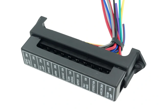
This image shows an automotive fuse box connector with printed circuit labels and a multi-wire harness. It helps illustrate how fuse box terminals and labeled positions support vehicle electrical distribution and circuit identification.
Do not start by pulling every fuse.
On an engine bay fuse box, the enclosure often tells the first part of the story. Heat, water, vibration, road splash, and previous repair work usually leave marks before the circuit becomes completely dead.
Begin with the outside of the box:
- Cover condition
- Missing or weak clips
- Gasket or seal damage
- Dirt tracks around the lid
- Water marks
- Corrosion near terminals or studs
- Burnt odor
- Housing distortion
A waterproof automotive fuse box only stays waterproof if the cover, seal, cable entry, mounting angle, and harness connectors are still doing their job. A cracked cover or loose latch can defeat the rating long before the internal parts fail.
Look for localized heat rather than only a melted box
A fuse box does not need to be fully melted to be unsafe.
Watch for smaller clues:
- Browned plastic around one cavity
- Softened fuse slot
- Darkened relay terminal
- Discolored fuse blade
- Warped cover area
- Loose terminal tension
- Burn mark near a main feed stud
These signs often point to heat at the connection, not only current overload in the branch.
That distinction matters. A fuse responds to current through the circuit. It may not open if the load current stays below its rating. But a poor contact can still generate heat at the fuse terminal, relay socket, bus joint, or harness connector.
The useful formula is simple:
Pheat = I² × R
A small increase in contact resistance can become serious at automotive current levels. The fuse may look normal while the cavity around it slowly darkens.
Use a Fuse Box Damage Severity Matrix
| Condition | Severity | Recommended Action |
| Clean and dry, no discoloration | Low | Continue normal inspection |
| Light corrosion at cover or edge | Medium | Find the moisture path and inspect terminals |
| Browned fuse cavity | High | Diagnose contact resistance and branch load |
| Melted plastic near terminal | Critical | Stop and assess repair or replacement |
| Standing water inside box | Critical | Diagnose ingress before energizing |
| Loose main feed or terminal | High | Repair by approved procedure before reuse |
This matrix helps separate cosmetic dirt from electrical risk. A dusty box is not automatically bad. A slightly brown fuse cavity, however, deserves a closer look.
When does an interior fuse box need a different service strategy?
An interior fuse box usually fails under different conditions than an under-hood box.
The cabin location is protected from direct road splash, but it creates access problems. The box may sit behind a trim panel, under the dashboard, near the glove compartment, or in a footwell where visibility is poor. A rushed repair can break trim clips, damage nearby wiring, or short a low-current control circuit.
Interior electrical centers may also be close to body-control modules, communication wiring, lighting circuits, and convenience electronics. Random probing is risky.
Prioritize access, labeling, and controlled testing
Before touching the fuse panel, confirm:
- Correct trim removal path
- Fuse map availability
- Approved test points
- Fuse family and rating
- Circuit label
- Whether the circuit is always-on, switched, or module-controlled
- Final trim reinstallation check
Do not use the interior fuse box as a convenient place to borrow power just because it is easy to reach. If a new accessory needs its own branch, a separate protected circuit is usually cleaner than stacking wires into factory positions.
For added loads, TEJIATE’s Fuse Block Selection Guide is the better place to handle circuit count, bus capacity, branch protection, and accessory distribution.
The point is traceability. If the same vehicle returns with an intermittent interior electrical fault, the technician should know exactly which cavity was checked and what was changed.
Decide whether the problem is a fuse, relay, terminal, bus, or box
Replacing the whole automotive fuse box too early is an expensive guess.
Start with the symptom. One dead branch, several related dead branches, and a whole box losing power do not point to the same fault level.
A single dead circuit may involve:
- Blown fuse
- Weak fuse terminal
- Branch wire fault
- Failed load
- Local connector issue
Several related dead circuits may point toward:
- Shared relay
- Common feed
- Bus section
- Control signal
- Connector group
Several unrelated dead circuits raise bigger questions:
- Main input feed
- Battery-side distribution
- Box connector engagement
- Internal bus damage
- Ground or module-control issue where applicable
If the issue starts after adding lights, radio equipment, pumps, or other accessories, separate the added wiring from the OEM fuse box diagnosis. TEJIATE’s Inline Fuse Holder Selection Guide can be used when one remote accessory branch needs its own local protection outside the factory box.
Separate blown-fuse diagnosis from fuse-box failure
A blown fuse alone does not prove the fuse box is defective.
The fuse may have opened because of a downstream short, motor fault, pinched harness, water in the load, or wrong accessory wiring. Installing a new fuse without finding the cause can hide the problem until the next failure.
The opposite can also happen. A fuse may test good, but the branch still fails under load because the terminal contact is weak.
That is where loaded voltage drop becomes useful:
Vdrop = I × R
A poor connection can pass a low-current continuity test and fail when the real load operates. A meter may show voltage with no load, then the circuit collapses when the motor, lamp, relay coil, or module begins drawing current.
Build a Fuse Box Fault-Isolation Tree
| Symptom | Likely Check Path |
| One branch dead | Fuse → fuse terminal → branch wiring → load |
| Several related branches dead | Shared relay → common feed → bus section |
| Several unrelated branches dead | Main input → connector → distribution path |
| Relay chatter | Relay coil feed → ground/control → terminal tension |
| Heat or melting | Loaded voltage drop → terminal resistance → branch load |
| Water or corrosion | Ingress path → terminals → connector side → replacement decision |
Do not skip the connector side. Damage can sit under the visible fuse layer, especially where harness terminals enter from below or behind the box.
How do you qualify an automotive fuse box replacement?
Physical fit is not approval.
An automotive fuse box replacement must match the vehicle application and electrical architecture. Two boxes can share the same housing style while routing power differently inside. One may have a different bus layout, relay assignment, connector pinout, or optional-equipment population.
Before approving a replacement, verify:
- Exact vehicle make, model, year, and powertrain
- Approved fuse-box part number
- Connector count
- Connector keying
- Terminal cavity layout
- Internal bus architecture
- Fuse and relay map
- Electrical ratings
- Mounting points
- Cover and seal design
- Environmental location
A relay fuse box deserves extra caution because relay function is not defined by socket shape alone. A relay may plug in while using a different contact arrangement, suppression design, or control behavior.
Use an Automotive Fuse Box Replacement Gate
Do not approve the part until each gate passes.
| Gate | Pass Requirement |
| Vehicle application | Exact or approved cross-reference |
| Box P/N | Matches service or sourcing requirement |
| Connector count | Same as original design |
| Connector keying | No forced fit or modified lock |
| Pinout | Verified against documentation |
| Bus architecture | Same feed and branch routing |
| Fuse layout | Same cavity map and ratings |
| Relay layout | Same relay type and function |
| Mounting | No stress on box or harness |
| Environmental protection | Suitable for engine bay, cabin, or rear location |
This is where buyers and technicians often need the same language. The buyer sees a housing and connector count. The technician sees pinout, relay logic, fuse rating, and service-map risk. The replacement is only acceptable when both views line up.
Keep OEM fuse boxes separate from auxiliary fuse blocks
The OEM automotive fuse box is part of the vehicle’s original electrical architecture. Treat it that way.
It is tied to the factory harness, relay logic, circuit labeling, fuse ratings, connector pinout, and service documentation. Changing it to support new lights, radios, pumps, or control modules can create faults that are hard to trace later.
An accessory fuse box has a different job. It protects added circuits without disturbing the factory fuse panel. For several new accessory branches, it is usually cleaner to design a dedicated protected distribution point than to crowd wires into OEM terminals or increase factory fuse ratings.
Use the OEM box when repairing an existing vehicle circuit. Use a separate fuse block when new loads need their own branches. TEJIATE’s Fuse Block Selection Guide is the more suitable reference for accessory circuit count, bus capacity, and branch protection.
Avoid stuffing multiple new wires into factory fuse-box terminals
A factory terminal was not designed as a general expansion point.
Adding extra wires can reduce terminal grip, increase local resistance, loosen the fuse contact, or create heat at a point the fuse may not protect correctly. The same logic applies near the battery side. TEJIATE’s battery-terminal guidance recommends using proper distribution hardware instead of stacking accessory wires onto one connection point.
Use an OEM Box vs Auxiliary Block Decision Tree
| Situation | Better Path |
| Repairing a factory circuit | Follow OEM fuse-box service path |
| Replacing a damaged factory box | Match exact vehicle application and P/N |
| Adding one approved accessory branch | Use a dedicated protected circuit |
| Adding several new accessory circuits | Evaluate an auxiliary fuse block |
| Modifying internal OEM bus or pinout | Stop and use vehicle-specific engineering documentation |
Do not increase a factory fuse rating to “make room” for an accessory. A larger fuse may protect the accessory, but it may no longer protect the original wire.
How should a fuse-and-relay box be checked after repair or replacement?
After repair, the box still has to prove itself under real operating conditions.
A quick continuity check is not enough. The technician should compare the old layout record, service map, replacement box, installed fuses, relay part numbers, connector locks, and main input condition before energizing the vehicle.
Start with the main feed. A fuse-and-relay box cannot distribute voltage that is not reaching its input. Then check branch outputs under real load, not only with a no-load meter reading.
A weak terminal can show normal voltage until the circuit operates. Once current flows, voltage drop appears and the load fails.
Confirm relay-controlled functions separately from fuse-only circuits
A relay circuit has more conditions than a fuse-only branch.
Check:
- Relay P/N
- Coil feed
- Control signal
- Contact arrangement
- Load-side output
- Suppression method where applicable
- Heat at the relay socket
Modern modules can be more than passive fuse rows. Eaton’s mRFRM multiplexed rear-fed fuse and relay module uses CAN communication over SAE J1939 and combines relay control, fuse/circuit-breaker sockets, and monitored component states in one sealed module.
That is the practical takeaway: on newer or specialized vehicles, replacement may require matching communication and control architecture, not only connector shape and cavity count.
For relay-coil or motor switching problems, link the diagnosis out to TEJIATE’s RC Snubber for 12 V Relay & Motor Damping instead of turning this fuse-box article into a suppression-design guide.
A repaired box should not leave the bench simply because the cover fits. It should pass layout, electrical, thermal, and functional checks.
Build the RFQ and incoming inspection plan for replacement or aftermarket boxes
For sourcing, appearance is the weakest specification.
A proper RFQ for an automotive fuse box should define the electrical architecture first. Buyers should not request only “20-way fuse box” or “12V fuse relay box” without explaining how many positions are fuses, relays, circuit breakers, spares, or sealed connector outputs.
Required RFQ fields include:
- Vehicle or application
- Nominal voltage and maximum voltage
- Fuse families
- Number of fuse positions
- Relay positions
- Spare cavities
- Internal bus architecture
- Main current rating
- Branch current range
- Harness connectors
- Terminal series
- Mounting points
- Engine-bay, interior, or rear location
- IP or environmental requirement
- Operating temperature
- Drawing revision
- Sample quantity and production quantity
Littelfuse’s configurable DC power distribution modules show why this matters: fuse count, relay count, bus structure, sealing, voltage rating, and current capacity are separate design choices.
Increase IQC after design or supplier changes
Incoming inspection should become stricter when anything changes:
- Bus layout
- Terminal series
- Housing material
- Cover seal
- Connector keying
- Fuse fit
- Relay fit
- Drawing revision
- Production tooling
- Supplier source
For aftermarket or replacement supply, inspection should include visual checks, connector fit, terminal retention, continuity, cover sealing, fuse insertion feel, relay seating, and critical dimensions.
FAQ
How do I know whether I should open the engine-bay fuse box or the interior fuse box?
Use the fuse map or service information for the exact make, model, and year. Location alone is not enough because vehicles may divide protection among engine-bay, cabin, rear, and auxiliary electrical centers.
Does an empty socket in a car fuse box mean a fuse is missing?
Not always. It may be an optional-equipment cavity, unused relay position, spare location, or unpopulated variant. Verify it before inserting anything.
Why can a fuse-box cavity melt even though the fuse never blows?
Local resistance can generate heat according to P = I²R. A loose, corroded, or weakened terminal may overheat while current remains below the fuse-opening threshold.
Can I use a replacement automotive fuse box if all connectors plug in?
No. Physical fit is only one check. Verify P/N, pinout, connector keying, bus routing, fuse layout, relay layout, mounting, electrical rating, and environmental protection.
Should new lights or radio equipment be connected directly to the factory fuse box?
Not automatically. Added loads need engineered protection. For multiple new circuits, a separate fuse block is usually cleaner than modifying the OEM fuse box.
Why can a replacement fuse box show voltage with no load but fail under load?
A high-resistance terminal, bus, connector, or fuse contact can pass a meter reading and still create excessive voltage drop during real operation. Loaded voltage-drop testing is more useful than continuity alone.
Final practical note
Treat the automotive fuse box as a mapped electrical center, not a generic holder for blade fuses.
For repair, identify the correct box, capture the fuse and relay layout, inspect for heat or water damage, and test under load. For replacement or sourcing, qualify the part by vehicle application, connector system, pinout, bus architecture, fuse layout, relay layout, and environmental rating.
If new accessories are being added, keep that work separate from the OEM box. A clean auxiliary distribution path is easier to document, inspect, and troubleshoot later.
For automotive power-distribution parts, fuse holders, inline protection, and related connector assemblies, TEJIATE can support sourcing review, sample confirmation, and production inspection based on the actual application requirements.
