
A cable assembly can fit the antenna, tighten correctly, and still be the wrongRF part.
That usually happens because the antenna coax connector was selected as a visible interface rather than as one element in the complete RF path. The buyer checks “SMA male,” “N female,” or “BNC,” but nobody records the coax diameter, impedance, panel transition, mating frequency, or mechanical load behind it. The first sample may work. Problems appear later when a different cable is substituted, the assembly is installed through a chassis, or the antenna is moved outdoors.
A better selection process starts with the system, not the connector catalog. Trace the antenna, cable, bulkhead, adapters, and radio port as one RF chain, then decide which connector family and termination actually fit that job. That system-level selection task is the focus of this guide.
Where does the connector sit in the complete antenna path?
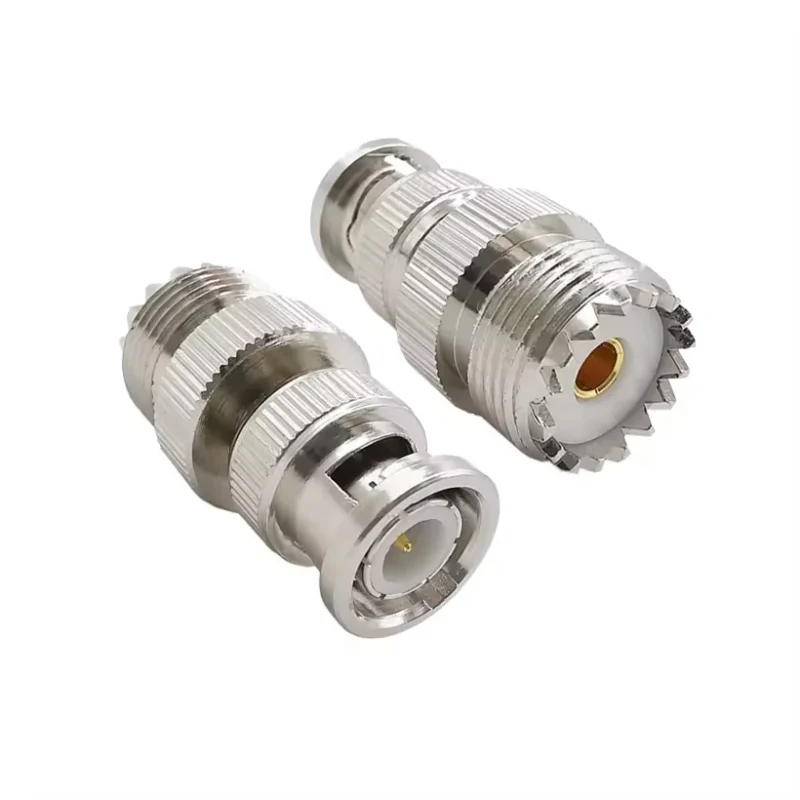
Before specifying an antenna cable connector, draw the RF path from end to end.
A useful starting model is:
Antenna → Antenna Connector → Coax Cable → Bulkhead / Adapter → Device RF Port
That line looks simple, but procurement errors often appear because only one point on it is specified. A drawing may call out the antenna-side connector while leaving the cable undefined. Another BOM may specify the coax but describe the device end only as “SMA.” In either case, the supplier has to make assumptions.
The connector should therefore be recorded by position and function. Is it permanently attached to the antenna? Is it terminating the feeder cable? Does it pass through an enclosure? Is it an adapter added because the radio and cable ends do not match? Those positions create different mechanical requirements even when the visible RF interface is the same.
Draw the RF chain before selecting any connector
Take a compact outdoor gateway as an example. The antenna may terminate in N-Type, the external feeder may use a larger low-loss coax, the enclosure may carry an N-Type bulkhead, and a short flexible cable inside the enclosure may transition to SMA at the radio.
Calling the whole assembly an “N antenna cable” hides most of the information needed to build it correctly.
The same problem appears in smaller equipment. An embedded receiver may use a miniature internal pigtail while the external service point is a threaded SMA bulkhead. The connector at the PCB is selected for space; the connector at the enclosure is selected for handling. They should not be treated as interchangeable design decisions.
Separate the antenna connector from the antenna cable
An RF antenna connector defines the mating interface, but the coax still determines much of the length-dependent attenuation, routing flexibility, and termination geometry. The two decisions are linked.
For sourcing purposes, “N-Type connector” is incomplete information. The rear termination may be designed for one cable diameter and completely unsuitable for another. The ferrule, dielectric entry, center contact, braid interface, and strain-relief geometry all depend on the intended cable.
This is why two parts with the same front interface should not automatically be treated as substitutes.
TEJTE’s existing SMA-specific selection guide makes the same system-level distinction for SMA interfaces: the connector is a 50-ohm RF transition, and cable selection and connector selection should not be made independently.
Identify where repeated mating actually occurs
Mating frequency changes the design problem.
A rooftop feeder may be installed once and left untouched for years. A laboratory antenna may be disconnected several times in one test session. A removable antenna on a gateway may be handled by installers or end users. An internal pigtail may never be disconnected after production.
That distinction affects coupling style, strain relief, access, inspection, and where the service interface should be placed. If the smallest connector in the system is attached directly to a PCB, repeated antenna changes can transfer mechanical load to the board. Moving the service point to a panel-mounted connector or short replaceable pigtail can isolate that load.
A useful design record is therefore not just “connector type.” Record the interface at each position, cable family, impedance, operating band, environment, and expected servicing. That single path map can eliminate several rounds of supplier clarification later.
Which connector family best matches the antenna’s mechanical job?
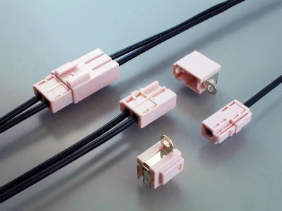
Automotive antenna coax connector components showing cable-to-cable and PCB-mount configurations for compact vehicle RF interconnects.
Connector families should not be ranked as “better” or “worse.” They solve different mechanical problems.
A compact threaded interface makes sense where enclosure space is tight. N-Type becomes attractive when the antenna system uses a larger feeder and needs a mechanically substantial external interface. BNC is useful where quick connection and disconnection matter. TNC trades that quick bayonet action for threaded retention, which can be useful in vibration-prone equipment. The actual frequency and electrical limits still have to be confirmed from the specific connector part number rather than assumed from the family name.
Use compact threaded interfaces where space dominates
Compact radios, gateways, embedded receivers, and many GPS-related products often have little room around the RF port. A small threaded connector can keep the enclosure practical without forcing a large mechanical transition at the device.
SMA is an obvious example, but this article does not need to turn into another SMA reference page. Detailed SMA gender, polarity, cable compatibility, and antenna-interface decisions are better handled in TEJTE’s dedicated SMA connector selection guide.
The more important rule is to keep “compact” from becoming the only requirement. A small connector may fit the enclosure beautifully while forcing the designer to use a thinner coax than the link budget allows.
Choose N-Type when feeder size and external durability dominate
An N type antenna connector is a more natural fit when the system moves toward larger coax, longer external feeder runs, outdoor antennas, or mechanically substantial equipment. The larger body provides more room for cable termination and can make the transition from a stiff feeder into an antenna or enclosure easier to manage.
That does not mean N-Type should automatically replace SMA in every outdoor system. If the device is compact, the better architecture may be a short internal flexible cable feeding an N-Type panel interface rather than trying to route the large feeder directly to the PCB.
TEJTE already uses this radio-to-outdoor-antenna architecture in its SMA-to-N system guidance, where a compact radio interface transitions toward a larger outdoor antenna or feeder connection.
Use BNC where fast connect and disconnect matter
The bayonet coupling of a BNC antenna connector makes it practical for bench equipment, temporary antenna setups, and systems where connectors are changed frequently. It is especially useful when an operator needs to connect or disconnect without threading a coupling nut every time.
The trade-off is mechanical retention. If the assembly is exposed to vibration or persistent cable movement, a threaded interface may deserve more attention.
Use TNC when threaded retention matters more than quick release
A TNC antenna connector addresses a different service requirement. Its threaded coupling provides positive retention, which can make it more appropriate for vehicle radios, industrial RF hardware, or other installations where vibration matters more than rapid removal.
The selection can be summarized by task rather than by connector popularity:
| Engineering requirement | Compact threaded | BNC | N-Type | TNC |
| Tight enclosure space | Strong fit | Moderate | Weak | Moderate |
| Fast servicing | Moderate | Strong fit | Moderate | Moderate |
| Threaded retention | Yes | No | Yes | Yes |
| Larger feeder support | Limited by variant | Moderate | Strong fit | Moderate |
| Vibration-focused installation | Variant-dependent | Lower priority | Good | Strong fit |
| Outdoor system integration | Possible with proper design | Application-dependent | Common fit | Common fit |
| Typical antenna role | Compact device port | Lab / temporary setup | External feeder / antenna | Rugged mobile / industrial |
This table is a selection aid, not a frequency-rating chart. A connector family name cannot replace the drawing and datasheet for the actual part number.
How do you keep the antenna system on the correct impedance path?
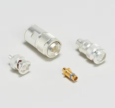
A comparison of RF antenna coax connectors in different body sizes and coupling styles for cable, adapter, and equipment-port applications.
A connector that mates is not necessarily an RF match.
That distinction matters because a physical interface can appear correct even when the complete antenna path contains the wrong impedance variant, an unsuitable adapter, or a poorly controlled transition. Thread engagement and center-contact mating only prove that two mechanical interfaces can connect. They do not prove that the assembly remains on the intended impedance path.
Start at the radio port and trace impedance all the way to the antenna
Treat the RF chain as one continuous electrical path:
Radio port → connector → coax → bulkhead or adapter → cable connector → antenna
For a typical 50-ohm antenna system, each of those elements should be checked rather than assumed.
A purchasing mistake often starts with a line item such as “50-ohm coax cable” while the connectors and adapters are ordered separately. If one transition is the wrong impedance version, the complete assembly may still pass continuity. The problem is more likely to appear later as higher reflection, unstable return loss, or a poor VNA result near the operating band.
This 50-ohm antenna path audit is especially useful when different suppliers provide the antenna, cable assembly, and enclosure hardware. It turns impedance from an assumption into a BOM-controlled requirement.
Do not use continuity as proof of RF compatibility
Continuity is useful, but only as an initial electrical gate.
It can confirm that the center conductor is connected and that an obvious open circuit is absent. It cannot prove correct impedance, acceptable return loss, low VSWR, or controlled high-frequency behavior.
This matters during incoming inspection. A production cable can pass a basic multimeter check while still being wrong for the intended RF system.
The TEJTE content standard specifically treats continuity and RF performance as separate issues: the full assembly still has to be considered in terms of impedance, VSWR, insertion loss, termination quality, cable length, bend radius, and connector count.
How should cable diameter influence connector selection?
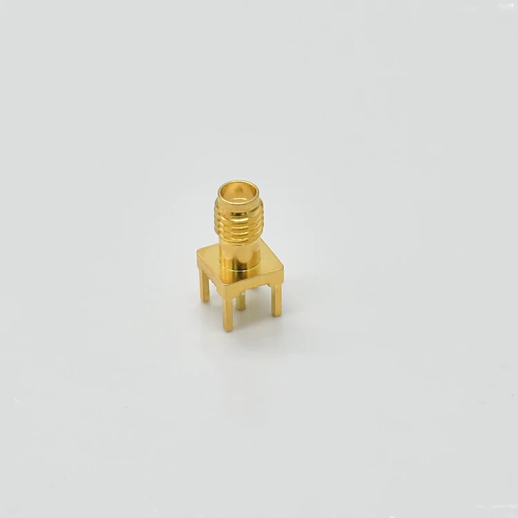
Gold-plated SMA female PCB-mount antenna connector featuring a straight interface, center contact, and four supporting ground legs.
The front interface gets most of the attention in product photos. The rear termination is where many sourcing errors actually occur.
Before comparing connector brands or plating options, confirm the physical cable construction that has to enter the connector.
That means checking:
- jacket outside diameter
- shield or braid diameter
- dielectric diameter
- center conductor size
- ferrule dimensions
- clamp or crimp structure
- expected bend radius
These dimensions determine whether the connector can be terminated correctly.
Match the rear termination before comparing connector brands
Two connectors can both be described as SMA male or N male and still require completely different coax.
A connector designed around miniature coax may have a narrow rear body and small ferrule. A connector intended for RG58-class or larger cable needs different mechanical dimensions. Substituting one for the other can produce poor braid contact, inadequate crimping, excessive dielectric deformation, or an assembly that simply cannot be terminated consistently.
The existing TEJTE RG Cable Guide is the better place to compare RG cable families in detail. In this connector-selection workflow, the practical rule is simpler: choose the cable architecture first, then confirm that the connector rear body was actually designed for it.
Keep miniature coax where short routing and flexibility matter
Miniature cable is useful in places where the run is short and mechanical space is limited.
Typical examples include:
- GPS receiver pigtails
- internal Wi-Fi links
- compact radio modules
- short PCB-to-bulkhead assemblies
The benefit is routing flexibility and reduced connector size, not automatically lower RF loss.
If the cable run becomes longer, the attenuation requirement may push the design toward a larger low-loss feeder. At that point, forcing the system to keep a tiny connector purely for packaging convenience can create the wrong trade-off.
Do not reduce cable size only to make the connector fit
This is a common integration shortcut.
The enclosure is already designed. A connector fits the available panel opening, but the preferred low-loss coax is too large for its rear termination. The easy response is to reduce the cable diameter.
That decision should be checked against the loss budget first.
Changing to a thinner cable can affect attenuation, shielding, mechanical durability, and bend behavior. The connector may become easier to install while the overall RF path becomes worse.
A practical comparison looks like this:
| Design Factor | Miniature Coax | Medium Coax | Larger Low-Loss Feeder |
| Routing flexibility | High | Moderate | Lower |
| Connector body size | Small | Medium | Larger |
| Rear termination | Compact | Moderate | Substantial |
| Typical run | Short | Short to medium | Medium to long |
| Strain relief need | Important | Important | High |
| Main sourcing risk | Wrong miniature variant | Ferrule mismatch | Undersized connector / tight bend |
The goal is not to make one cable class “better.” It is to keep cable loss, connector geometry, and installation mechanics aligned.
Which connector should a GPS or GNSS antenna use?
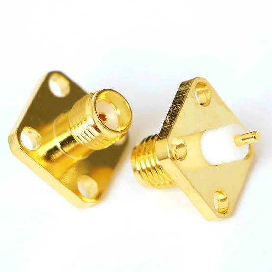
Gold-plated SMA female four-hole flange antenna connectors designed for fixed panel, enclosure, and RF module installations.
GPS and GNSS systems add another sourcing detail: the antenna path may carry more than the received RF signal.
An active antenna can also depend on DC bias supplied through the coax. That means a connector or cable substitution should not be approved only because the mechanical interface looks correct. The complete receiver-to-antenna path has to remain compatible with the intended RF and bias arrangement.
Separate the receiver-side port from the external antenna interface
A GPS receiver may use a miniature connector internally while the finished enclosure presents a larger serviceable interface externally.
A common architecture is:
Receiver PCB → short miniature coax pigtail → panel connector → external GPS/GNSS antenna
That arrangement lets the PCB stay compact while moving repeated connection and cable load away from the miniature receiver interface.
It is especially useful when an antenna may be replaced during field servicing.
Check active or passive antenna status before changing the assembly
Before changing connector style, cable type, or adding an adapter, record:
- active or passive antenna
- receiver port
- antenna-side interface
- required frequency bands
- cable length
- whether bias voltage is present
- expected mating frequency
- outdoor exposure
- need for a panel transition
That record is more useful than simply specifying “GPS antenna connector.”
TEJTE’s dedicated GPS Antenna Cable Guide should carry the deeper discussion of active/passive antenna architecture and specific GPS connector options. This article only needs enough GPS detail to make the antenna coax connector decision correctly.
When should Wi-Fi equipment use a cable connector instead of a direct antenna?
Adding an extension cable is not automatically an improvement.
A direct antenna keeps the RF path short and reduces connector count. A cable becomes useful when it allows better antenna placement: away from an enclosure, above an obstruction, outside a cabinet, or at a more useful orientation.
The gain in placement has to justify the additional feed-line loss and extra RF transitions.
Verify SMA versus reverse-polarity interfaces before ordering
Wi-Fi equipment is a good example of why the connector name alone is insufficient.
The buyer should confirm:
- outer coupling interface
- center pin or socket
- device port
- antenna-side connector
- extension-cable end configuration
A cable that threads onto the device is not automatically the correct polarity configuration.
Detailed SMA and reverse-polarity identification belongs in TEJTE’s specialist SMA/Wi-Fi content rather than being repeated here. The practical purchasing rule is to record both the outer interface and center-contact arrangement before placing the order.
When does an antenna connector belong on the chassis instead of the cable?
A bulkhead connector is primarily a mechanical architecture decision.
If an external antenna cable can pull directly on an internal PCB connector, the RF design may be electrically simple but mechanically weak. A chassis-mounted transition moves the external load to the enclosure.
A common layout is:
RFPCB → flexible pigtail → bulkhead connector → external antenna cable
This architecture is useful for outdoor radios, gateways, test equipment, vehicle electronics, and systems with replaceable antennas.
Define the panel before ordering the bulkhead
“Bulkhead SMA” or “bulkhead N-Type” is still incomplete.
The supplier needs enough mechanical information to confirm that the connector can actually be installed:
- panel thickness
- effective thread length
- washer and nut stack
- coating thickness
- O-ring or sealing requirement
- anti-rotation requirement
- cable clearance behind the panel
A connector can be electrically correct and still fail mechanically because the panel is too thick for the available thread.
A bulkhead does add another RF transition, so it should not be sold as an automatic RF-performance upgrade. Its main benefits are panel integration, mechanical support, serviceability, and protection of the internal connector. Electrical performance still depends on the complete installed path.
That distinction becomes more important in outdoor equipment, where the next question is no longer just where to mount the connector, but how the complete interface should be sealed against the environment.
How should outdoor exposure change the connector specification?
“Waterproof connector” is not a complete engineering specification.
An outdoor antenna connection can let moisture enter through several different paths: the mating interface, the connector-to-panel joint, the rear cable entry, an unused port, or the enclosure itself. Protecting only one of those points does not make the full installation weather-resistant.
Treat waterproofing as a system condition
Before ordering a waterproof antenna connector, define the actual installation state.
Is the required environmental protection expected:
- only while the connector is fully mated?
- while an unused port is covered with a cap?
- at the panel joint?
- at the cable entry?
- during permanent outdoor exposure?
- only against occasional splash?
A threaded N-Type or TNC interface may provide good mechanical retention, but thread engagement alone should not be treated as proof of a specific environmental rating.
The final enclosure and connector configuration has to be evaluated as one system.
A useful outdoor inspection should cover six areas:
Mating interface → panel joint → cable entry → protective cap → enclosure interface → moisture or drainage path
That is a better purchasing requirement than writing only “IP67 connector” in the RFQ without identifying the installed condition.
Choose the connector after calculating the feed-line loss budget
The connector should not be optimized in isolation if the cable already consumes most of the RF budget.
For a coaxial run:
Cable Loss = Cable Attenuation at Frequency × Cable Length
The complete feed path is closer to:
System Insertion Loss = Cable Loss + Connector Transitions + Adapter Transitions + Design Margin
The exact values must come from the cable and component data used in the project. The useful point is the accounting method: every transition belongs in the same budget.
Let the loss budget decide when a larger cable is justified
A miniature connector and thin coax may be perfectly reasonable for a 100 mm internal pigtail.
The same architecture may be poor for a long external antenna run.
If cable attenuation becomes the dominant penalty, moving to a larger low-loss feeder can matter more than changing to a connector with a higher nominal frequency rating. The new cable may then require a physically larger rear termination or a different panel interface.
That is why connector selection sometimes changes after the cable loss calculation rather than before it.
How should connector choice change for test, GPS, and outdoor RF systems?
The same connector should not be selected by habit across different antenna applications.
A laboratory antenna system prioritizes repeatable servicing and easy inspection. GPS/GNSS equipment may prioritize compact routing and continuity of the active-antenna bias path. Vehicle and outdoor radio systems shift attention toward vibration, cable support, and environmental sealing. Long feeder systems make cable attenuation a larger part of the decision.
A practical decision sequence is:
Application → main constraint → cable architecture → connector mechanics → environmental requirement → RF verification
That sequence prevents the connector catalog from becoming the starting point for every project.
Verify the complete antenna interconnect after installation
A good drawing does not guarantee a good installed RF path.
Assembly changes the system. A cable may be bent more tightly than it was during bench testing. A bulkhead may put stress on the pigtail. A connector can be under-torqued, contaminated, or misaligned. Outdoor sealing hardware can also change the mechanical loading around the interface.
Start with workmanship inspection:
- correct connector family and gender
- correct polarity where applicable
- cable compatibility
- clean threads and center contact
- proper strain relief
- correct sealing hardware
Then use continuity only as the first electrical gate.
For RF-critical assemblies, the installed path may also need S11, S21, return-loss, VSWR, or cable-loss verification according to the project requirement.
Compare the free assembly with the installed condition
For a first article or engineering sample, comparing the cable before and after installation can reveal problems that visual inspection misses.
Useful checks include:ΔS11 = S11 installed − S11 referenceand,
where transmission measurement is relevant:ΔS21 = S21 installed − S21 reference
A significant change can point toward a sharp cable bend, connector stress, panel loading, an added adapter, or another installation effect.
Build a supplier-ready antenna connector specification
“Need one antenna connector” gives a supplier almost nothing to work with.
A usable RFQ should describe both the mating interface and the system behind it.
For the connector, record:
Connector family + gender + center contact + mounting style + impedance
Then add:
- operating frequency range
- cable family and cable dimensions
- finished cable length
- straight or right-angle configuration
- free-cable or bulkhead mounting
- panel thickness where applicable
- outdoor or sealing requirement
- insertion-loss or return-loss target if controlled
- strain-relief requirement
- inspection or test documentation
- prototype and production quantities
This turns the request into something that engineering, purchasing, and production can all interpret the same way.
FAQ
How can I tell whether an antenna connector actually matches the coax behind it?
Check more than the front interface. Confirm jacket diameter, braid or shield size, dielectric diameter, center conductor, ferrule, and rear termination. Two connectors may both be called SMA or N-Type while being designed for different coax constructions.
Should I upgrade the connector or coax first when cable loss is too high?
Calculate the complete feed-line loss first. On longer runs, cable attenuation is often the larger length-dependent penalty. If a lower-loss coax requires a larger termination, change the connector architecture afterward rather than assuming a different connector alone will solve the loss problem.
Is N-Type always the best connector for an outdoor antenna?
No. N-Type works well in many outdoor and larger-coax installations, but enclosure space, cable diameter, vibration, service requirements, operating band, and sealing architecture can make another interface more practical.
Can GPS and Wi-Fi antenna connectors be interchanged?
Not based on coax alone. GPS/GNSS and Wi-Fi systems may use different connector families, polarity arrangements, frequency bands, and device interfaces. GPS systems may also involve active-antenna bias power through the coax.
Does adding a bulkhead connector improve RF performance?
Not automatically. A bulkhead primarily provides panel integration, mechanical support, and protection for the internal PCB connection. It also adds another RF transition, so the complete path still needs to meet the project’s electrical requirements.
Can sealing tape make any antenna connector waterproof?
No. Tape may be part of an installation method, but environmental protection also depends on the mating interface, panel joint, cable entry, unused-port protection, and enclosure design.
Should an antenna connector be VNA-tested after installation?
For RF-critical, higher-frequency, long-cable, or mechanically stressed installations, first-article testing after installation is useful. Comparing S11, S21, return loss, or other specified RF measurements can reveal problems caused by cable routing or connector stress.
Final buying guidance
Do not select an antenna connector from the interface name alone.
Start with the complete RF path. Confirm impedance. Match the rear termination to the actual coax. Decide whether the cable should terminate freely or at a bulkhead. Account for outdoor exposure, mating frequency, vibration, and cable loss. Then define how the finished assembly will be inspected.
If you are requesting an antenna cable assembly from a supplier, send the operating frequency, impedance, connector configuration, cable type, cable length, mounting method, environmental requirement, and RF inspection target together.
That information is usually more valuable than asking for a “better” connector without defining what the antenna system actually needs.
