
A technician connects a 4.3-10 base-station port to an SMA-equipped analyzer. The threads mate, continuity passes, and the setup looks harmless.
Then the analyzer input is overloaded.
In another installation, the electrical test passes, but the rigid adapter and attached feeder place enough leverage on the small SMA jack to loosen it from the instrument panel. A third adapter is sold as “low PIM,” yet the measured result changes every time the SMA test cable is remated.
These are not unusual connector failures. They are selection failures.
A 4.3-10 to SMA adapter links two RF interfaces built for very different mechanical and application environments. The 4.3-10 side is commonly associated with wireless-infrastructure equipment and low-PIM signal paths. The SMA side is compact and widely used on test instruments, modules, fixtures, cables, and lower-power RF equipment.
The adapter must be selected as part of the complete path—not as a metal part that merely changes the thread.
Where Should a 4.3-10-to-SMA Adapter Sit in the RF Path?
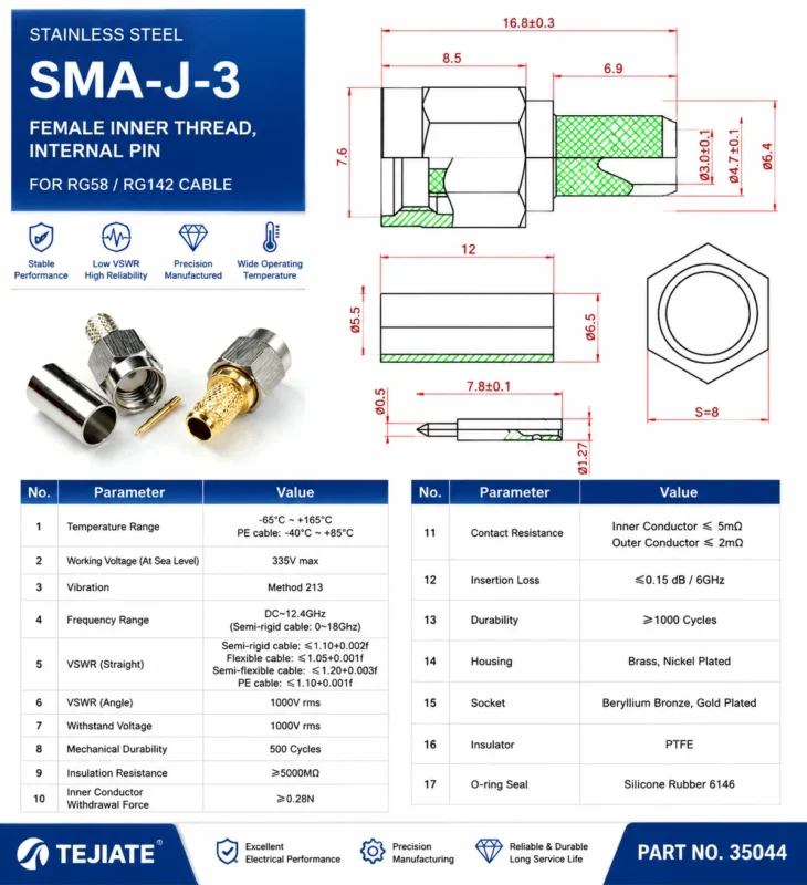
Start with the equipment at both ends.
A typical commissioning path may look like this:
4.3-10 Radio or DAS Port→ 4.3-10-to-SMA Adapter→ SMA Test Cable→ VNA, Signal Analyzer, or Power Sensor Another path may use a 4.3-10 feeder interface to reach an SMA measurement module or test fixture.
The drawings may look similar, but the engineering requirements are not. A low-level sample port, for instance, is different from a full transmitter output. A temporary VNA connection is also different from a permanent installation exposed to vibration, cable movement, and outdoor temperature changes.
Before choosing the adapter, document:
- Source equipment and port
- Destination equipment and port
- Operating frequency
- RF power at the transition
- Intended connection duration
- System impedance
- PIM requirement
- Existing cable and adapter count
For background on the larger infrastructure interface, review the 4.3-10 connector guide. It explains the connector family, coupling options, and typical wireless-system roles.
Separate measurement access from permanent distribution
A rigid adapter can work well during short, controlled bench measurements. It becomes less attractive when a heavy feeder remains attached to a small SMA port for months.
Temporary uses include:
- Site commissioning
- Troubleshooting
- Laboratory verification
- PIM investigation
- Production fixture testing
Permanent uses may involve:
- Base-station monitoring hardware
- Embedded measurement modules
- DAS equipment
- Fixed RF distribution assemblies
Long-term use requires more attention to support, strain relief, environmental sealing, and mating-cycle durability.
Remove unnecessary adapter stacks
It is rarely the cleanest option.
Each transition introduces another pair of mating interfaces, another possible impedance discontinuity, and another part that can loosen or become contaminated. A direct adapter or properly specified cable assembly usually creates a more controlled path.
That does not mean “shortest” is always best. A short flexible assembly may protect the SMA port better than a large rigid adapter.
RF Path Role Card
| Field | Required Entry |
| Source equipment | Model and installed port |
| Destination equipment | Model and installed port |
| Intended role | Test, commissioning, or permanent |
| System impedance | Ω |
| Operating band | MHz or GHz |
| RF power at transition | W or dBm |
| PIM requirement | dBc or not required |
| Existing adapter count | Quantity |
| Recommended architecture | Adapter, pigtail, or test cable |
This card can be attached to an RFQ or internal engineering approval. It prevents the buyer from ordering from a product photograph alone.
Which Installed Ports Define the Exact Adapter?
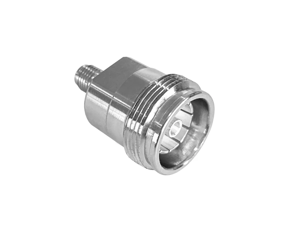
“4.3-10 to SMA” is not a complete part description.
The adapter can be built in several interface combinations:
- 4.3-10 male to SMA male
- 4.3-10 male to SMA female
- 4.3-10 female to SMA male
- 4.3-10 female to SMA female
The required adapter ends must mate with the ports already installed on the equipment.
Confirm the 4.3-10 interface
Check:
- Male or female interface
- Center pin or center socket
- Screw, hand-screw, or push-pull coupling
- Equipment-mounted or cable-mounted port
- Available coupling clearance
- Straight or angle-entry requirement
Do not identify gender from the body size alone. Confirm the center contact and mating geometry against a drawing.
Confirm the SMA side
The SMA side requires the same care.
Record:
- SMA male or female
- Center pin or socket
- Standard SMA or reverse-polarity configuration
- Equipment port or cable end
- Straight, right-angle, or bulkhead layout
- Port depth and surrounding clearance
Standard SMA and RP-SMA parts can appear similar in a small product photograph. Mixing them causes a mechanical or center-contact mismatch even though the threaded shells may look familiar.
The SMA adapter guide provides a broader reference for SMA gender, configuration, and adapter selection.
Port Pair Matrix
| Existing 4.3-10 Port | Existing SMA Port | Required Adapter | Characterized Test Cable |
| 4.3-10 female | SMA female | 4.3-10 male to SMA male | Usually longest |
| 4.3-10 female | SMA male | 4.3-10 male to SMA female | Best |
| 4.3-10 male | SMA female | 4.3-10 female to SMA male | Good |
| 4.3-10 male | SMA male | 4.3-10 female to SMA female | Preferred |
| Unknown | Unknown | Inspect both interfaces first | Can be specified |
| Heavy 4.3-10 hardware | Higher risk | Better | Better |
| Custom routing | Low | High | High |
| Production repeatability | Must be validated | Must be validated | Preferred |
| Insertion loss | VNA | Maximum dB | |
| PIM, if required | PIM analyzer | Maximum dBc | |
| Remating variation | Repeated RF test | Maximum change | |
| Body looseness | Inspection | None permitted | |
| Final decision | Combined review | Approve or reject |
Before approving the final SKU, add five checks:
- Center contacts confirmed
- SMA polarity confirmed
- Coupling form confirmed
- Product drawing reviewed
- Overall length and tool clearance accepted
Can the SMA End Safely Accept the Available RF Power?
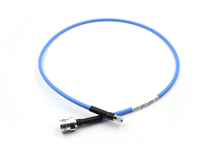
Blue flexible RF cable assembly with a 4.3-10 female connector and an SMA male connector. It is suitable for test access and installations where a rigid adapter could place excessive leverage on the SMA port.
The SMA interface is often the limiting point in this transition.
A 4.3-10 port may be installed on equipment capable of carrying far more RF power than an SMA test cable, analyzer input, limiter, or measurement module can tolerate. The adapter does not reduce that level.
Use the lowest verified rating in the chain:
Psystem,max =minimum of P4.3-10, Padapter, PSMA, Pcable, Pinstrument, and Pload
The review should include:
- Continuous-wave power
- Peak power
- Frequency-dependent derating
- Ambient temperature
- Load VSWR
- Connector condition
- Duty cycle
- Instrument input limit
A part that survives 100 W at one frequency and under matched conditions should not automatically be approved for the same power at another frequency or under high reflection.
Distinguish sampled power from transmitter power
These connections are not equivalent:
- Directional-coupler sample port
- Low-level monitor port
- Signal-generator output
- Power-sensor input
- Full transmitter output
- High-power feeder line
A VNA or analyzer should not be connected to an unknown live transmitter port merely because an adapter is available.
When the instrument cannot accept the signal level, the path may require:
- Directional coupler
- Fixed attenuator
- High-power attenuator
- Limiter
- Power sensor
- Properly rated termination
SMA-Side Power Approval Gate
This simple gate catches an expensive mistake before the test lead reaches the equipment.
How Should Low-PIM Claims Be Qualified at an SMA Interface?
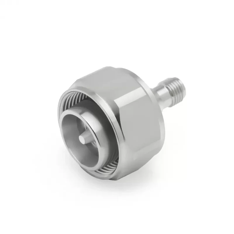
Low PIM is relevant in multi-carrier cellular systems, DAS installations, shared antenna systems, and high-power transmit paths. It may be less important for a low-level laboratory connection where ordinary S-parameter repeatability is the main concern.
The words “low PIM” are not enough for procurement approval.
Ask for:
- Maximum PIM result in dBc
- Carrier frequencies
- Power per carrier
- Intermodulation order
- Forward or reverse measurement
- Test duration
- Mating hardware
- Torque condition
- Maximum measured result
- Sample quantity
IEC 62037-1:2025 provides general requirements and measurement methods for passive intermodulation testing of passive RF and microwave components. The standard reference is available through the IEC Webstore.
The SMA mating interface affects the result
Even when the adapter body is designed for low PIM, the measured path includes the SMA mate.
Results can change because of:
- Loose SMA coupling
- Dirty threads
- Damaged plating
- Metal particles
- Worn test cables
- Side-loaded contacts
- Extra adapters
- Inconsistent remating
For comparison testing, use the same test cable, torque method, reference plane, carrier settings, and remating procedure.
A low-PIM 4.3-10 side does not cancel a poor SMA connection.
Which Frequency Limit Controls the Finished Transition?
Use the lowest verified frequency rating across the entire setup:
fsystem,max =minimum of f4.3-10, fadapter, fSMA, fcable, and finstrument
Do not assign the complete adapter the highest theoretical rating associated with one connector family.
An SMA connector family may include products intended for different frequency ranges. The internal geometry, dielectric support, mating quality, body construction, and manufacturing tolerance of the actual SKU determine its usable performance.
Likewise, commercial 4.3-10-to-SMA products are often designed around wireless-infrastructure bands rather than the upper limit sometimes associated with precision SMA hardware. The official 4.3-10-to-SMA adapter category shows that real configurations exist, but each SKU still requires individual specification review.
Test at the frequencies that matter
A single spot check near the middle of the band can hide edge problems.
Suggested acceptance points include:
- Lowest operating frequency
- Primary band center
- Highest operating frequency
- Band edges
- Harmonic measurement range
- Intermodulation frequencies
- Worst insertion-loss point
For a multi-band system, sweep the complete required range rather than testing only one cellular band.
The SMA connector guide can help verify why the name “SMA” alone does not define the final frequency capability.
When Does a Rigid Adapter Overload the SMA Port?
The mechanical mismatch is easy to underestimate.
The 4.3-10 end is physically larger. Add a long rigid adapter, a heavy feeder, and a horizontal SMA jack, and the smaller interface may be carrying a continuous bending load.
An approximate bending moment can be screened with:
M = F × d
Where:
Mis the moment applied to the SMA portFis the adapter, feeder, or side-load forcedis the distance from the panel or PCB support point
The formula is simple, but it exposes the problem: a modest force becomes more damaging as the unsupported length increases.
High-risk layouts include:
- PCB-mounted SMA jack
- Portable test instrument
- Unsupported horizontal connection
- Heavy 4.3-10 jumper
- Long adapter stack
- Repeated cable movement
- Vehicle or cabinet vibration
- Tight cable routing
Mechanical support options include:
- Short flexible SMA pigtail
- Supported 4.3-10 jumper
- Bulkhead transition
- Cable clamp
- Test fixture bracket
- Strain-relief loop
SMA Port Stress Score
Score each item from 1 to 5:
Port Stress Score =Adapter Mass+ Adapter Length+ Feeder Weight+ Side Pull+ Vibration+ SMA Port Weakness
This is an engineering screening tool, not an industry standard. It is useful during layout review when formal mechanical data is unavailable.
Choose an Adapter, Pigtail, or Test Cable by Use Case
A rigid adapter is not automatically better because it is shorter.
Use a rigid adapter when:
- Ports align naturally
- The connection is supported
- RF power is controlled
- Movement is limited
- Coupling tools have enough clearance
- The adapter is used for short bench work
Use a flexible pigtail when:
- The connector sizes create imbalance
- Ports are offset
- The SMA port is recessed
- The enclosure is crowded
- The 4.3-10 side is heavy
- The assembly may move
Use a characterized test cable when:
- VNA repeatability matters
- The cable is flexed during measurement
- Phase stability is specified
- The setup is used repeatedly
- Production results must be compared over time
For cable selection behind the adapter, use the SMA cable selection guide. Cable loss, phase behavior, shielding, and bend stability may become the bottleneck before the adapter does.
How Should the Adapter Be Calibrated Into a VNA Setup?
Decide where the measurement reference plane should sit.
The setup may be:
VNA Port→ Precision Test Cable→ SMA Interface→ 4.3-10-to-SMA Adapter→ DUT Possible treatments include:
- Keep the adapter as part of the DUT
- Characterize and de-embed the adapter
- Move calibration to the SMA side
- Move calibration to the 4.3-10 side with suitable standards
The correct choice depends on the measurement goal.
When qualifying the adapter itself, include it as the DUT. When measuring equipment behind it, move or correct the reference plane so the adapter does not distort the reported equipment result.
Record:
- Test cable identification
- Calibration kit
- Adapter serial or batch number
- Reference-plane location
- Torque condition
- Sweep range
- IF bandwidth
- Output power
- Remating count
For engineering comparison, save raw S11 and S21, adapter-only S-parameters, corrected DUT results, and remating variation.
A fixed but undocumented test setup can produce consistent-looking numbers that cannot be reproduced later.
What Evidence Must the First Article Provide?
Start with mechanical inspection before connecting expensive RF equipment.
Verify:
- Correct 4.3-10 gender
- Correct coupling form
- Correct SMA gender
- Standard SMA rather than RP-SMA
- Center-contact alignment
- Thread condition
- Body tightness
- Plating condition
- Overall length
- Drawing dimensions
Then perform continuity and isolation checks.
A straight adapter should normally show:
- Center-to-center continuity
- Shell-to-shell continuity
- Center-to-shell isolation
- No intermittent contact under light movement
Continuity is only the first gate. It does not prove RF performance.
First-Article Acceptance Standard
Repeat the test after several controlled mating cycles, light mechanical handling, and cable repositioning. A sample that passes only while untouched on the bench has not demonstrated much.
Write an RFQ That Prevents Interface and Rating Errors
A usable description names both ends completely.
Write:
4.3-10 Male to SMA Female Adapter 50 Ohm Straight For Low-PIM Test Access
Do not write:
4.3-10 SMA Adapter
The RFQ should separate interface, RF, PIM, mechanical, and reporting requirements.
Recommended RFQ Block
This block also improves BOM control. It gives suppliers enough information to reject an unsuitable substitution instead of guessing what “equivalent” means.
FAQ
Can a 4.3-10-to-SMA adapter connect a base-station port directly to a VNA?
It can provide the physical transition, but that does not prove the VNA input is safe. Confirm whether the 4.3-10 port is a low-level sample port or a full transmitter output. A directional coupler, attenuator, limiter, or power sensor may be required before the VNA. Never connect an instrument to an unknown live RF port.
Does a low-PIM 4.3-10 side guarantee low PIM through the SMA connection?
No. The measured path includes the SMA mate, test cable, surface condition, coupling torque, plating condition, and every additional transition. A low-PIM adapter can still produce unstable results when the SMA cable is worn, loose, contaminated, or side-loaded.
Why can the adapter pass continuity but fail at the operating frequency?
Continuity confirms only that a DC path exists. It does not check impedance uniformity, internal geometry, contact alignment, dielectric behavior, return loss, or insertion loss. The adapter may therefore pass a multimeter test and still show unacceptable mismatch during a VNA sweep.
Is SMA gender determined by signal direction?
No. Gender is determined by the physical mating interface, including the thread arrangement and center contact. Signal flow does not determine whether the adapter needs an SMA male or SMA female end. Inspect the installed equipment port and select the mating interface.
Is a rigid 4.3-10-to-SMA adapter suitable for permanent high-power use?
Only after the power rating, frequency range, load VSWR, thermal conditions, and mechanical support have been verified. The SMA side or attached cable may become the weakest part of the path. A supported cable assembly is often safer when the 4.3-10 hardware is heavy.
When is a flexible SMA test cable better than a rigid adapter?
Use a flexible cable when the ports are offset, the SMA connector is recessed, the 4.3-10 side is heavy, the setup moves frequently, or repeatability under flexure matters. The cable adds length and loss, but it can reduce damaging leverage on the SMA port.
What evidence should accompany the first adapter sample?
Request an interface drawing, dimensional inspection, continuity and isolation results, S-parameters across the required band, verified power information, PIM test data when applicable, and results after controlled remating. The report should also identify the test cable, calibration plane, torque condition, and sample number.
Final Selection Note
The correct 4.3-10-to-SMA transition is defined by more than two connector names.
Before ordering, confirm the installed genders, SMA polarity, coupling style, operating band, actual RF power, required PIM limit, mechanical support, test architecture, and inspection method. Where the larger 4.3-10 hardware could overload the smaller SMA port, move the mechanical stress into a supported pigtail or test cable.
A direct adapter can simplify the RF path. A flexible assembly can protect the equipment. The better choice is the one that remains electrically valid and mechanically controlled in the real installation—not the one that looks shortest in the catalog.
