
Identify the Transition Before Selecting the Adapter
The adapter arrived, both ends appeared to fit, and the site still failed its PIM test.
That result is more common than it should be. Procurement ordered a 4.3-10 to N adapter, the installer confirmed that the threads engaged, and continuity passed. The problem was not basic connectivity. The adapter had been selected without confirming the installed genders, 4.3-10 coupling method, feeder load, PIM test conditions, or whether the transition would remain on the tower permanently.
A between-series adapter is a mechanical and electrical transition. It does not correct an incompatible system, repair a damaged feeder, remove existing contamination, or turn an ordinary N-Type connection into a verified low-PIM interface.
The correct selection process starts with the site architecture—not the adapter catalog.
Which Migration Path Requires This Adapter?
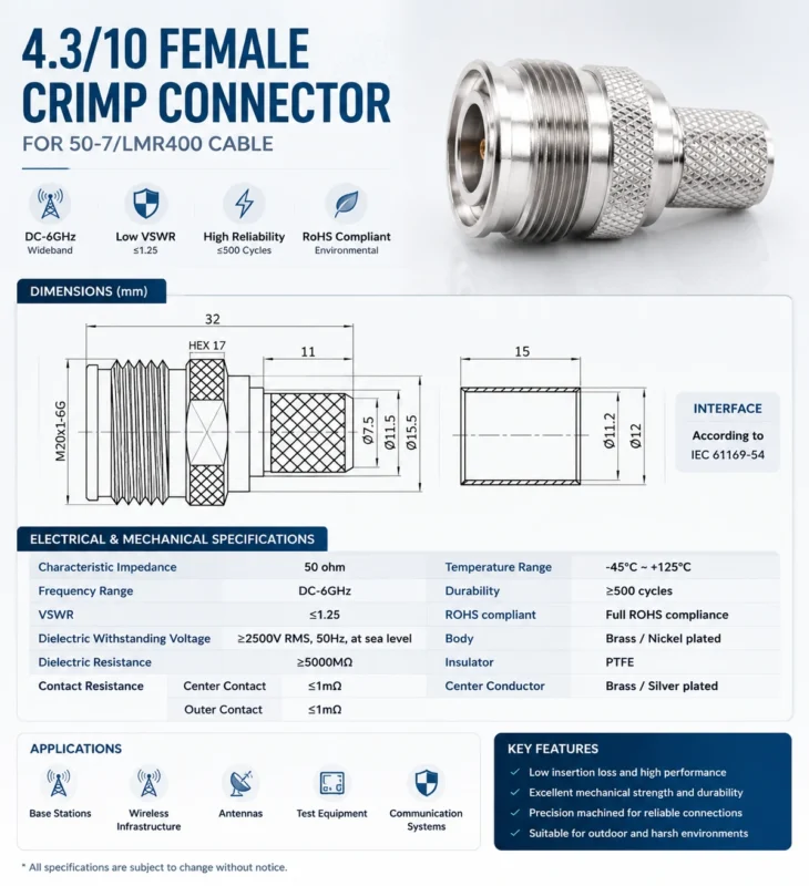
The usual application is straightforward on paper:
Existing N-Type Feeder→ 4.3-10 to N Adapter→ New 4.3-10 Radio Port In the field, several details sit behind those three lines. The old feeder may be rigid, unsupported, weathered, or terminated with an N connector that was never qualified for low-PIM service. The new radio may use a screw, hand-screw, or push-pull 4.3-10 interface. The adapter may be needed for one commissioning shift or expected to stay outdoors for ten years.
Those are different procurement tasks.
TEJTE’s broader comparison of 4.3-10 and N-Type connectors explains why 4.3-10 is commonly used in compact, low-PIM cellular infrastructure while N-Type remains common in legacy feeders and general outdoor RF systems. The adapter should therefore be treated as a migration component rather than proof that both architectures now have identical characteristics.
Bridge an existing feeder to new radio hardware
Before requesting a quotation, record:
- Existing feeder connector and gender
- New equipment port and gender
- Cable family and approximate feeder length
- Lowest and highest operating frequencies
- Maximum transmit power
- Site PIM target
- Indoor or outdoor installation
- Temporary or permanent service
- Available cable support
- Maintenance access
Do not begin with “We need an N to 4.3-10 adapter.” That description still leaves the supplier guessing which end requires a plug, which requires a jack, and how the 4.3-10 interface must couple.
Separate temporary migration from permanent architecture
A rigid adapter can be reasonable during:
- Radio commissioning
- Emergency restoration
- Mixed-generation equipment replacement
- Short-term compatibility testing
- Planned migration between upgrade stages
Permanent installation needs a tougher review. Cable weight, vibration, thermal movement, sealing, corrosion, remating history and maintenance access all become part of the approval.
A part that performs correctly on a clean bench may behave differently when a heavy feeder hangs from it in wind and rain.
Confirm the problem is connector compatibility
An adapter cannot fix:
- A 75-ohm component inside a 50-ohm path
- Excessive feeder attenuation
- Antenna mismatch
- Incorrect radio or antenna band
- Insufficient component power handling
- A corroded feeder connector
- Loose nearby metalwork generating PIM
- Water already inside the cable assembly
Use this decision path before approving an adapter:
This decision tree prevents a common sourcing error: solving a system-level problem with a connector-level part.
How Do You Convert Installed Ports Into the Correct SKU?
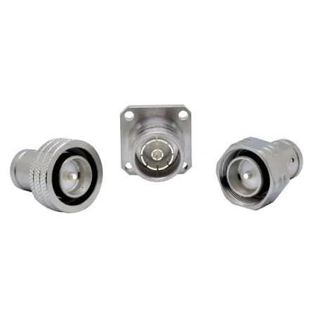
Examples of N-Type RF connector configurations in inline and flange-mount formats. The image supports identification of connector gender, center contact, mounting style and mating requirements when selecting a 4.3-10 to N adapter.
Connector gender should be determined from the mating interface, not from the direction of signal flow.
An adapter described as N female to 4.3-10 male normally represents the same two interfaces as a 4.3-10 male to N female adapter. RF direction does not change the hardware. Still, the drawing and purchase order should define each end separately.
Read 4.3-10 gender and coupling independently
A complete 4.3-10 description may need three pieces of information:
- Male or female mating interface
- Center contact pin or socket
- Screw, hand-screw or push-pull coupling method
The coupling design matters because it affects installation tools, accessibility, engagement and the field maintenance process. TEJTE’s 4.3-10 connector guide describes the family as a compact 50-ohm interface available with multiple coupling methods for cellular infrastructure.
Do not assume that every product called “4.3-10 male” is installed in exactly the same way.
Identify the N-Type gender and impedance
Check:
- Male plug or female jack
- Center pin or socket
- Rotating coupling nut or fixed external thread
- 50-ohm specification
- Panel, bulkhead or cable-mounted construction
- Existing weather seal
- Thread and contact condition
N-Type hardware also exists in configurations that should not be silently mixed into a standard 50-ohm RF system. The BOM should state the impedance rather than relying on appearance.
Use a port-pair matrix
| Installed 4.3-10 Port | Installed N Port | Required Adapter |
| 4.3-10 female | N female | 4.3-10 male to N male |
| 4.3-10 female | N male | 4.3-10 male to N female |
| 4.3-10 male | N female | 4.3-10 female to N male |
| 4.3-10 male | N male | 4.3-10 female to N female |
| Unknown | Unknown | Inspect both ports before quotation |
This matrix only establishes the mating ends. It does not approve the frequency, PIM, torque, power or environmental specification.
A real product family may include multiple between-series arrangements. Amphenol RF, for example, publishes straight 50-ohm 4.3-10-to-N configurations, including a 4.3-10 plug to N-Type jack version. That confirms that these combinations exist, but the selected manufacturer’s drawing must still control the order.
Can the N-Type Side Preserve the Low-PIM Objective?
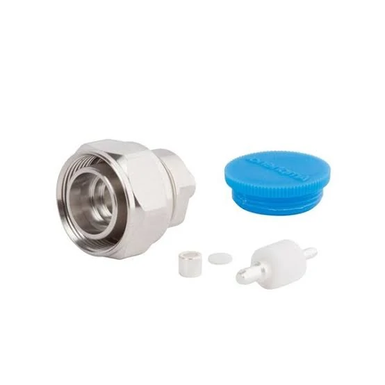
Components of a 4.3-10 RF connector used in cellular infrastructure and low-PIM installations. The image helps explain connector construction, contact inspection and component identification before installation.
“Low PIM adapter” is not the same as “low PIM installed system.”
The adapter is tested as one component under defined conditions. The field path includes both mating connectors, the feeder termination, possible surge protection, grounding hardware, antenna interfaces and surrounding metalwork.
Count every junction
A typical path may contain:
- The 4.3-10 equipment interface
- The 4.3-10 mating interface inside the transition
- The adapter’s internal conductor transition
- The N-Type mating interface
- The feeder connector
- A surge protector or coupler
- The antenna-side connector
The adapter may perform well while the old N connector remains contaminated, loose or mechanically stressed.
Separate laboratory data from installed performance
Supplier PIM data normally represents a defined setup:
- Clean samples
- Controlled mating hardware
- Specified carrier frequencies
- Defined carrier power
- Known test direction
- Calibrated test equipment
- Controlled torque
- Low-PIM termination
- New or documented mating history
A site adds variables that are not present in the report:
- Dirt or metal particles
- Damaged plating
- Cross-threading
- Incorrect torque
- Cable side load
- Corrosion
- Water ingress
- Loose grounding hardware
- Nearby ferromagnetic objects
Amphenol’s published 4.3-10 adapter series is promoted for low-PIM and low-return-loss infrastructure applications, with many products specified through 6 GHz and selected products extending higher. That is a useful product-family reference, not permission to apply one rating to every available SKU.
Build an installed PIM risk register
A supplier certificate should be placed in this register as evidence for one line—not treated as evidence for the entire installation.
Which PIM Test Conditions Must Appear in the Specification?
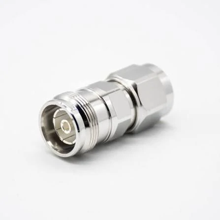
A straight 4.3-10 to N adapter designed for RF equipment, antenna systems and cellular infrastructure. Connector gender, impedance, frequency range, PIM requirements and coupling method should be confirmed before selection.
A PIM requirement written only as “≤ −160 dBc” is incomplete.
The result depends on test frequencies, carrier power, direction, duration, termination, connector condition and test method. Without these conditions, two suppliers can test the same adapter differently and both claim compliance.
Define the carrier pair and IM product
The RFQ should identify:
- Power applied at each carrier
- Intermodulation order
- Product frequency being measured
- Acceptance threshold in dBc
- Forward or reverse measurement
A pass result at one carrier pair does not automatically represent every operating band.
Use fixed points, multiple pairs or a sweep deliberately
IEC 62037-1:2025 notes that PIM generation is typically frequency dependent. Its updated reporting requirements also call for the maximum PIM measured during the test duration, rather than relying only on a favorable average or isolated reading.
For a multiband DAS or cellular site, procurement should therefore ask whether the supplier uses:
- One fixed carrier pair
- Several fixed carrier pairs
- A swept-frequency procedure
- A project-specific carrier plan
This does not mean every adapter requires the most complex possible test. It means the test method must represent the intended site.
Write a usable acceptance record
Ask for the maximum recorded value and the complete conditions. A certificate with only the product name and a single PIM number is difficult to audit later.
How Should Coupling Style and Torque Be Controlled?
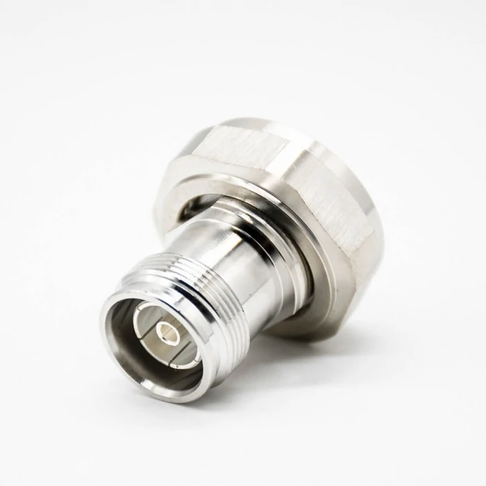
Close-up view of a 4.3-10 to N RF adapter used in low-PIM communication systems. The image highlights the center contact, mating surface, threads and hex body that should be inspected before installation.
Torque is an interface condition, not a universal setting for the entire adapter.
The 4.3-10 end and N-Type end may require different tools and installation methods. Applying one side’s torque rule to the other can damage threads, deform contacts, compress seals incorrectly or leave the connection under-engaged.
Match the coupling method to the maintenance plan
Screw coupling is often selected where a controlled permanent connection is required.
Hand-screw designs may improve service access where calibrated tool use is not part of the maintenance plan.
Push-pull hardware can reduce connection time where the selected port and adapter are specifically designed for it.
The connector family name alone does not identify the coupling style. It must appear in the product description or drawing.
Clean before final engagement
Inspect both ends for:
- Dust
- Loose metal particles
- Moisture
- Damaged O-rings
- Thread deformation
- Contact damage
- Plating wear
- Evidence of cross-threading
- Residue from previous sealing materials
A torque wrench does not repair a dirty interface. In some cases, tightening contamination into the contact area makes the result worse.
TEJTE’s outdoor RF connector installation guide also treats cleaning, correct engagement and waterproofing as separate controls rather than one installation step.
Keep a coupling control log
Record:
This is particularly valuable when several crews work across multiple sites. It turns “installed correctly” into a traceable statement.
When Does a Rigid Adapter Create More Risk Than a Jumper?
A rigid adapter creates a short RF path, but it also transfers mechanical load directly into the equipment port.
That trade-off is easy to miss during procurement because adapter drawings normally show dimensions, not the feeder hanging from the opposite end.
Estimate the port moment
A simple first-pass check is:
M=F×dM=F\times dM=F×d
Where:
- MMM is the approximate bending moment at the port
- FFF is cable weight or lateral force
- ddd is the distance from the equipment panel to the force point
This is not a substitute for a structural analysis. It is a screening tool.
If cable force or adapter length increases, the panel-port moment also increases. A thin radio panel, vibration, poor alignment or repeated maintenance can amplify the risk.
Flag high-risk conditions
Review the design when any of these are present:
- Large or stiff feeder
- Horizontal unsupported cable
- Offset connector axes
- Vibration
- Wind-driven movement
- Thermal expansion
- Long adapter body
- Thin equipment panel
- Frequent mating and unmating
- Difficult wrench access
A low-PIM jumper adds cable length and two terminated ends, but it can isolate the equipment port from feeder movement and alignment error.
Use an adapter-versus-jumper matrix
| Site Condition | Rigid Adapter | Low-PIM Jumper |
| Ports are aligned | Preferred | Suitable |
| Heavy feeder | Higher mechanical risk | Preferred |
| Temporary upgrade | Preferred | Optional |
| Permanent outdoor use | Must be qualified | Often safer |
| Vibration isolation | Limited | Better |
| Offset routing | Poor | Good |
| Minimum path length | Best | Longer |
| Strain isolation | Limited | Better |
| Replacement access | Easy if exposed | Easy if routed correctly |
The rigid adapter is not automatically the more professional option. In some installations, the flexible jumper is the more controlled architecture.
How Do You Protect the Outdoor Joint From Water and Cable Load?
An IP rating belongs to a tested product or assembly under defined conditions. It does not automatically transfer across an adapter stack.
Even if one connector interface is available in an IP-rated design, the complete path includes two mating interfaces, the adapter body, feeder termination and sealing workmanship.
Map each entry path
Inspect:
- 4.3-10 mating face
- N-Type mating face
- Adapter body seam
- O-rings and sealing surfaces
- Panel interface
- Feeder connector body
- Upward-facing joints
- Cable jacket entry
- Low points where water may collect
Amphenol’s 4.3-10 adapter catalog includes products with different performance and environmental attributes. This is another reason to verify the selected part number rather than applying a family-level assumption.
Support the cable before weatherproofing
Install the cable support first. Sealing tape is not a strain-relief clamp.
A practical outdoor plan may include:
- Feeder clamp
- Support bracket
- Drip loop
- Strain-relief point
- Weather boot
- Self-amalgamating tape
- UV-resistant outer layer
- Accessible inspection point
Waterproofing should not hide a visibly loose or overloaded connector.
Can One Frequency Rating Cover Every LTE and 5G Band?
Do not approve the first article from one product photograph and one selected test result.
The sample should be inspected, measured, remated and challenged in a way that represents field use.
Complete visual and DC checks
Verify:
- 4.3-10 gender
- 4.3-10 coupling style
- N-Type gender
- Center-contact alignment
- Thread condition
- O-ring presence and condition
- Overall dimensions
- Body and contact plating
- Center-conductor continuity
- Shield continuity
- Center-to-shield isolation
Repeat RF and PIM tests after handling
A practical sequence is:
- Inspect and photograph the sample.
- Measure initial S11 and S21.
- Complete the initial PIM test.
- Mate and unmate the adapter a defined number of times.
- Apply a controlled cable load or mechanical disturbance.
- Repeat S11 and S21.
- Repeat the PIM test.
- Compare the change from baseline.
- Inspect threads, contacts and plating again.
IEC 62037-3:2025 addresses PIM measurement in coaxial connectors under mechanical impact, reflecting the importance of identifying unstable contacts and contamination-related behavior rather than relying only on a static initial result.
Approve the worst acceptable sample, not only the best-looking unit.
Which RFQ Fields Prevent a Wrong Build?
A useful product name looks like this:
4.3-10 Male to N Female Adapter 50 Ohm Straight Low-PIM Application
A weak description looks like this:
4.3-10 N Adapter
The weak version does not lock the gender, orientation, coupling style, impedance or test requirements.
Use this RFQ block
Place the final approved drawing number and revision on the purchase order. Product descriptions can be shortened accidentally; controlled drawing references are harder to misinterpret.
When Should the Migration Adapter Be Removed From the Site?
A migration component should have an exit plan.
Without one, a temporary adapter can become permanent by default, even after corrosion, repeated retorquing or feeder movement changes its condition.
Define replacement triggers
Typical triggers include:
- PIM degradation
- Return-loss drift
- Visible corrosion
- Water ingress
- Loose engagement
- Repeated torque failure
- Excessive feeder load
- Frequent maintenance calls
- Completion of the site upgrade phase
- Damage after impact or cable movement
Move toward a native architecture
A more controlled permanent transition may be:
4.3-10 Radio Port→ Low-PIM 4.3-10-to-N Jumper→ Existing N-Type Feeder A later modernization phase may remove the N-Type transition entirely:
4.3-10 Radio Port→ Native 4.3-10 Feeder Architecture Neither solution is universally required. The point is to make the architecture intentional.
Standardize one approved adapter, jumper, torque method, sealing process, PIM test plan and inspection record across similar sites. That reduces field variation and makes failures easier to trace.
FAQ
Is a 4.3-10-to-N adapter electrically directional?
No. A passive straight-through adapter normally carries RF signals in either direction. “4.3-10 to N” identifies the two connector families, not an uplink or downlink direction. Gender and coupling details still need to be defined on the drawing.
Is N female to 4.3-10 male the same as 4.3-10 male to N female?
Usually, yes. Both descriptions identify a 4.3-10 male interface and an N-Type female interface. Procurement should nevertheless use one standardized naming order and include a drawing to prevent confusion.
Why can a factory-tested low-PIM adapter fail after installation?
The installed result includes contamination, connector torque, mating hardware, feeder condition, cable strain, corrosion, water exposure and nearby metalwork. A factory test confirms the component under the supplier’s stated conditions, not every condition at the site.
Can one fixed-frequency PIM test cover every site band?
Not necessarily. PIM behavior can change with frequency. A multiband system may need several carrier pairs or a swept procedure to identify the worst result. IEC 62037-1:2025 specifically notes frequency dependence and maximum-value reporting.
Should a female-to-female adapter be preferred for migration work?
No. Female-to-female is not inherently better. The required combination is determined by the two installed ports. Selecting gender by preference instead of mating requirements usually produces a part that cannot be installed.
When is a low-PIM jumper safer than a rigid adapter?
Use a jumper when the feeder is heavy, the ports are offset, vibration is present, cable movement would load the radio port, or the transition will remain outdoors for a long period. The jumper provides routing and strain isolation.
What should procurement request when a supplier only states “low PIM”?
Request the maximum PIM value, carrier frequencies, power per carrier, intermodulation order, test direction, duration, frequency method, torque condition, mating hardware, sample history and complete test report.
Final Specification Note
A 4.3-10 to N adapter should be ordered only after the installed ports, coupling method, operating band, PIM conditions, cable load and environmental plan are documented.
Send the supplier clear port photographs, equipment models, an approved interface drawing, site frequencies, maximum power, PIM threshold and installation conditions. Those details make it possible to decide whether the correct solution is a rigid adapter, a low-PIM jumper or a native cable retermination.
The adapter is the smallest component in the migration path. It should not be the least specified.
