
A short jumper can create a long troubleshooting session.
The cable may have the correct 4.3-10 connector, pass a continuity check, and fit between the radio and feeder. After installation, however, the site reports unstable PIM, excessive insertion loss, or a connector that gradually loosens because the cable is pulling sideways on the port.
The problem is usually not the interface name alone. A finished 4.3-10 coax cable has to be selected as one complete RF and mechanical assembly. Connector gender, coupling style, coax construction, length, bend radius, PIM behavior, power level, sealing, and installation support all affect the result.
This guide focuses on finished jumpers used in base stations, DAS systems, rooftop radio installations, cabinets, antenna systems, and other wireless-infrastructure projects. It does not replace the connector drawing or supplier datasheet. Its purpose is to help engineers and buyers write a cable specification that can be built, tested, installed, and inspected without relying on assumptions.
Which Field Task Justifies a 4.3-10 Coax Cable?
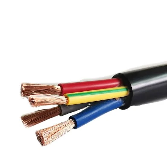
Close-up of a flexible black-jacketed cable containing color-coded stranded copper conductors, used to explain how conductor construction and cable flexibility affect jumper routing and mechanical stress.
A rigid adapter works when two ports are aligned, mechanically supported, and close enough to connect without loading either interface. Many field installations do not meet those conditions.
Radio heads, antenna ports, feeder cables, DAS nodes, and equipment panels are often offset from one another. A flexible jumper provides the missing routing distance while isolating the equipment connector from the weight and stiffness of the main feeder.
Typical uses include:
- Radio unit to main feeder transitions
- Antenna port to low-loss feeder connections
- DAS node connections
- Rooftop radio jumpers
- Cabinet-to-panel RF links
- Legacy feeder migration
- Equipment replacement where the new port position differs
The practical distinction between raw coax and a finished cable assembly also matters. Raw coax has no installed connector ends. It still requires cutting, stripping, termination, inspection, and assembly-level RF testing.
A finished 4.3-10 cable assembly should already have:
- Connector A installed
- Connector B installed
- Cable type identified
- Overall length and tolerance defined
- Terminations inspected
- Continuity confirmed
- Required RF tests completed
- Labeling and traceability applied
4.3-10 Cable Architecture Selector
| Installation Task | Recommended Architecture | Main Reason |
| Two ports directly aligned | Rigid adapter | Minimum connection length |
| Radio connected to heavy feeder | Flexible jumper | Isolates port from feeder load |
| Equipment installed at separate locations | Cable assembly | Provides controlled routing |
| Permanent outdoor connection | Sealed low-PIM jumper | Supports environmental protection |
| Temporary commissioning work | Short jumper or adapter | Easy to replace |
| Several adapters used in series | One-piece assembly | Reduces interface count |
| Repeated RF measurement | Characterized test cable | Better measurement repeatability |
A flexible jumper is not automatically the safer option. If it is too short, too stiff, unsupported, or bent immediately behind the connector, it may transfer more load to the port than a correctly supported rigid connection.
How Should the Two Cable Ends Be Named?
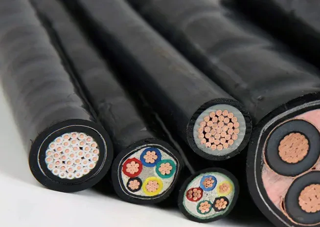
Cross-sectional comparison of several cable constructions, illustrating differences in conductor size, insulation layers, outer jackets, and internal architecture when selecting a cable for a 4.3-10 RF jumper assembly.
“4.3-10 cable” is not a complete product description.
The 4.3-10 family includes male and female interfaces, different coupling systems, straight and right-angle bodies, and cable-mounted or equipment-mounted configurations. The mating port on each side must be identified before the cable ends can be specified.
For each end, confirm:
- Male or female interface
- Center contact pin or socket
- Screw, hand-screw, or push-pull coupling
- Straight or right-angle body
- Cable-mounted or panel-mounted mating port
- Required installation clearance
- Mating reference plane
The opposite end does not have to be another 4.3-10 connector. Common finished assemblies include:
- 4.3-10 to 4.3-10
- 4.3-10 to N-Type
- 4.3-10 to SMA
- 4.3-10 to 7/16 DIN
- 4.3-10 to a project-specific RF interface
For a mixed-interface assembly, both mating ports must be checked independently. A phrase such as “4.3-10 to N jumper” still leaves two unanswered questions: which gender is required at each side, and which coupling version is used on the 4.3-10 end?
Cable-End Configuration Matrix
| Existing Port A | Existing Port B | Required Cable Ends |
| 4.3-10 female | 4.3-10 female | Male to male |
| 4.3-10 female | 4.3-10 male | Male to female |
| 4.3-10 male | 4.3-10 female | Female to male |
| 4.3-10 male | 4.3-10 male | Female to female |
| 4.3-10 port | N-Type port | Confirm both mating genders |
| Unknown port | Unknown port | Request photographs and drawings |
A normalized description is much harder to misread:
Connector A: 4.3-10 Male, Screw Coupling Connector B: 4.3-10 Male, Screw Coupling Impedance: 50 Ohm Overall Length: 1,000 mm
Photographs help, but a photograph alone may not show the contact geometry, thread arrangement, or exact coupling version. For custom production, include the connector drawing or request an approval drawing before the first article is built.
Which Coax Construction Fits the Route?
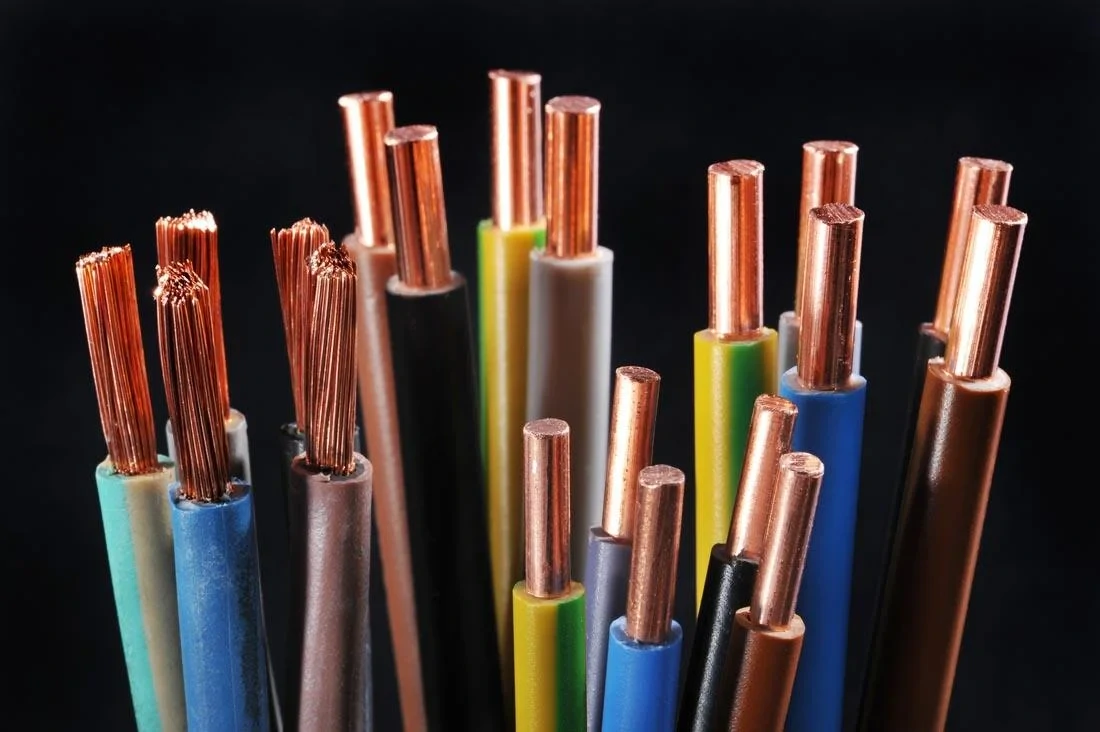
Close-up comparison of solid and stranded copper conductors, supporting the discussion of cable flexibility, bend behavior, mechanical durability, and conductor construction in cable assembly selection.
The lowest-loss cable is not always the best jumper cable.
A large low-loss coax may perform well in an attenuation table but be too stiff for a compact radio cabinet. A smaller flexible cable may route cleanly but consume too much of the link-loss budget over a longer distance.
The cable has to satisfy both sides of the design.
Flexible coax is generally useful for:
- Short equipment jumpers
- Tight cabinets
- Offset connector locations
- Rooftop radio transitions
- Installations requiring occasional maintenance
- Routes that need a controlled service loop
Larger or lower-loss cable becomes more attractive when:
- The route is longer
- The operating frequency is higher
- The available insertion-loss margin is small
- Continuous RF power is high
- The assembly is permanently installed outdoors
Check more than the nominal cable family. Two cables with similar diameters may use different braid coverage, foil construction, jacket materials, dielectric structures, attenuation values, and temperature ratings.
The selected 4.3-10 termination must also be designed for that exact cable size. A connector body, ferrule, rear seal, or center contact made for one cable cannot be assumed to fit another cable with a similar product name.
Coax Construction Scorecard
A practical comparison can be made with the following model:
Cable Suitability Score =Loss Margin+ Power Margin+ Outdoor Durability+ Routing Flexibility+ Connector − Bend-Radius RiskCompatibility− Port-Stress Risk Rate each field from 1 to 5. The total is not a universal engineering standard. It is a sourcing tool that forces the buyer to compare electrical and mechanical risks at the same time.
| Evaluation Field | Required Entry |
| Cable model | Manufacturer and part number |
| Nominal impedance | Ω |
| Attenuation at target frequency | dB/m |
| Outer diameter | mm |
| Minimum bend radius | mm |
| Maximum rated power | W |
| Jacket environment | Indoor or outdoor |
| 4.3-10 termination available | Yes or no |
| Final recommendation | Approve or review |
A cable should be rejected when it fits electrically but forces an unsafe route. Warning signs include an immediate bend behind the connector, excessive side load, unsupported cable weight, an incompatible outdoor jacket, or a cable diameter outside the connector termination range.
The broader RG cable guide can be used to compare coax construction, attenuation, shielding, and routing characteristics before the connector ends are finalized.
How Can Length Be Turned Into an Insertion-Loss Limit?
Physical route length is only the starting point.
The cable must be long enough to reach the ports without tension, but short enough to remain inside the RF loss budget. Extra length added “for safety” increases attenuation and may create a large coil that is difficult to support.
The first estimate is the cable attenuation at the actual operating frequency:
ILcable = α(f) × L
Where:
α(f)is the cable attenuation at the target frequency in dB/mLis the cable length in meters
The estimated assembly loss should also include the two connector transitions and any remaining interfaces:
ILestimated =α(f) × L+ ILA+ ILB+ ILextra For early design work, the maximum cable length can be estimated from the remaining loss margin:
Lmax =(ILlimit − ILA − ILB − ILextra)÷ α(f) This calculation is useful for comparing candidate cables. It does not replace a VNA measurement of the completed assembly.
Cable attenuation normally changes with frequency. A jumper intended for a multiband system should not be accepted from a result taken at only one convenient test point. At minimum, evaluate:
- Lowest operating frequency
- Center of the required band
- Highest operating frequency
- Critical carrier frequencies
- Worst measured point across the sweep
4.3-10 Cable Loss Budget Calculator
| Input | Symbol or Entry |
| Operating frequency | f |
| Cable attenuation | α(f) |
| Cable length | L |
| Connector A contribution | ILA |
| Connector B contribution | ILB |
| Additional interface loss | ILextra |
| Estimated total loss | Calculated result |
| Maximum allowed loss | ILlimit |
| Remaining margin | Limit minus estimate |
| Decision | Pass, shorten, or change cable |
Do not copy the connector loss from one unrelated assembly and treat it as a guaranteed value. Termination quality, cable construction, connector design, test fixtures, and calibration reference planes can all affect the measured result.
What Makes a Finished Jumper Low-PIM?
A low-PIM connector does not automatically create a low-PIM cable assembly.
The finished result depends on the entire conductive path, including:
- Connector contact geometry
- Contact pressure
- Plating condition
- Cable materials
- Shield termination
- Cleanliness
- Soldering or crimp quality
- Mechanical strain
- Cable bending
- Mating condition
- Test setup
The 4.3-10 interface is widely positioned for compact, low-PIM wireless infrastructure. That makes it a suitable starting point, not complete proof of the jumper’s PIM performance.
A purchasing specification should state the test conditions rather than only writing “low PIM.” At minimum, define:
- Maximum permitted PIM in dBc
- Carrier 1 frequency
- Carrier 2 frequency
- Power per carrier
- Intermodulation order
- Forward or reverse test direction
- Test duration
- Mating condition
- Maximum recorded result
- Whether movement or tapping is included
Static testing can miss a mechanically unstable termination. A useful qualification sequence is:
- Record the initial PIM result.
- Reposition the cable within a controlled bend.
- Apply the agreed mechanical disturbance.
- Repeat the measurement.
- Record the maximum result and change from baseline.
- Inspect the termination if the value becomes unstable.
Low-PIM Cable Test Record
| Field | Required Value |
| Cable assembly ID | Serial number or batch |
| Carrier 1 | MHz |
| Carrier 2 | MHz |
| Power per carrier | dBm or W |
| Intermodulation order | IM3 or other |
| PIM limit | dBc |
| Initial result | dBc |
| Post-movement result | dBc |
| Maximum recorded result | dBc |
| Connector mating condition | Recorded condition |
| Cable routing condition | Recorded condition |
| Final result | Pass or fail |
Insertion loss, return loss, VSWR, and PIM must remain separate acceptance items. A cable can have acceptable S21 and still produce unstable PIM. It can also pass PIM while having an unacceptable impedance discontinuity elsewhere in the assembly.
For background on coupling versions and field installation requirements, see the 4.3-10 connector guide.
How Should Bend Radius and Support Points Be Set?
Coils of color-coded insulated wire illustrating how cable diameter, jacket construction, flexibility, and available routing space can affect the installation of a finished cable assembly.
The cable should not begin a sharp turn at the rear of the connector.
A bend that stays outside the cable manufacturer’s minimum radius may still be unsuitable when it starts directly at the termination. That location is already carrying the mechanical transition between the connector and coax.
Allow the cable to leave the connector naturally before changing direction. Then place supports where they can carry the cable weight without crushing the jacket or forcing the coax into a smaller radius.
The routing drawing should define:
- Port-to-port distance
- Overall cable length
- Minimum bend radius
- First-bend distance
- Clamp locations
- Unsupported cable length
- Service-loop allowance
- Expected side load at each connector
A service loop provides room for equipment removal, remating, thermal movement, and future maintenance. It should not become an oversized coil. Excess cable increases loss, occupies installation space, creates additional contact points, and makes field inspection harder.
Can the Assembly Survive the Outdoor Site?
An IP-rated connector does not make every finished jumper IP-rated.
The complete assembly includes several exposure points:
- The mated 4.3-10 interface
- Connector-to-cable transition
- Heat-shrink, boot, or overmold
- Cable jacket
- Panel penetration
- Upward-facing joint
- Clamp and support locations
- Areas where water can collect
Request evidence for the assembly that will actually be supplied. Useful documentation includes:
- Complete assembly IP test report
- Cable jacket datasheet
- UV-resistance statement
- Operating temperature range
- Moisture exposure limits
- Sealing drawing
- Transition-area inspection standard
Outdoor installation planning should also show how water moves around the route. Drip loops, weather boots, sealing tape, UV-resistant outer wrapping, support spacing, and inspection access are part of the installed system.
Avoid placing a sealed joint where it cannot be inspected or replaced. Weatherproofing should protect the interface without hiding an unsupported or incorrectly mated connector.
How Do Power and Temperature Change the Cable Choice?
The usable power limit is set by the lowest-rated part of the assembly.
Psystem,max =minimum of Connector A rating, Connector B rating, Cable rating, Assembly rating
The number should then be reviewed against operating frequency, ambient temperature, load VSWR, reflected power, duty cycle, cable bundling, and solar exposure.
An RFQ should distinguish:
- Continuous-wave power
- Peak power
- Duty cycle
- Number of carriers
- Maximum reflected power
- Ambient temperature
- Maximum expected cable temperature
Heat can concentrate at terminations, tight bends, cable bundles, enclosed cabinets, and sections exposed to direct sunlight. A cable that operates safely in an open laboratory may require derating when installed in a crowded outdoor enclosure.
Use project-specific manufacturer data for the final decision. A general power claim taken from the connector family page is not enough to qualify a complete cable assembly.
Which Tests Should Approve the First Article?
RF testing should begin after the assembly has passed basic dimensional and workmanship inspection.
First confirm:
- Correct connector at each end
- Correct coupling version
- Cable model
- Overall length
- Length tolerance
- Connector orientation
- Jacket condition
- Heat-shrink or overmold condition
- Labeling
- Body tightness
- Visible damage
Continuity should then be checked through the center conductor and shield. Center-to-shield isolation must meet the project requirement. Light cable movement during the check can help expose an intermittent termination.
VNA testing should record:
- Calibration method
- Reference planes
- Sweep range
- Return loss
- VSWR
- Insertion loss
- Worst frequency
- Sample identification
For mechanically sensitive or low-PIM assemblies, repeat the test after controlled flexing and remating. The comparison from baseline can reveal a cable that passes in a straight bench condition but changes after installation handling.
4.3-10 Cable First-Article Standard
| Test Item | Method | Acceptance Field |
| Connector A | Drawing and visual check | Correct or incorrect |
| Connector B | Drawing and visual check | Correct or incorrect |
| Cable model | Documentation check | Correct or incorrect |
| Overall length | Measurement | Target ± tolerance |
| Center continuity | DMM | Pass or fail |
| Shield continuity | DMM | Pass or fail |
| Isolation | Resistance test | Project limit |
| Return loss | VNA | Minimum dB |
| VSWR | VNA | Maximum ratio |
| Insertion loss | VNA | Maximum dB |
| Initial PIM | PIM analyzer | Maximum dBc |
| Post-flex PIM | Repeated measurement | Maximum result or change |
| Bend inspection | Visual and dimensional | Pass or fail |
| Final decision | Combined review | Approve or reject |
Define whether the supplier must provide a type-test report, first-article report, batch report, or individual serial-numbered result. The test level changes the product cost and production flow, so it should be agreed before the purchase order is released.
The RF test cables guide provides additional context for calibration, reference planes, and measurement repeatability.
How Should Buyers Build the Part Number and RFQ?
A useful part number should identify the configuration without forcing the factory to guess.
A normalized product description could read:
4.3-10 Male to 4.3-10 Male Coax Cable 50 Ohm, Low PIM 1,000 mm Overall Length Outdoor Base-Station Jumper
The RFQ should separate cable, connector, electrical, environmental, and reporting requirements.
4.3-10 Coax Cable RFQ Block
Also state whether length is measured between connector reference planes, body ends, or cable cut points. Different measurement conventions can produce a cable that is technically within one interpretation but wrong for the installation.
When Should the Cable Assembly Replace an Adapter Chain?
Adapter stacks often grow one part at a time.
A route may begin with one transition and later become:
4.3-10 Port→ 4.3-10-to-N Adapter→ N Coupler→ Short N Cable→ Another Adapter→ Equipment Every additional junction creates another opportunity for mismatch, contamination, looseness, mechanical leverage, and PIM instability.
Where the end interfaces are known, a purpose-built cable can simplify the path:
4.3-10 Port→ Purpose-Built 4.3-10 Cable Assembly→ Equipment The comparison can be expressed as:
Interfaces Removed =Interfaces Before − Interfaces After
Estimated Loss Reduction =Loss Before − Loss After
Replace the chain when two or more adapters are used in series, the existing arrangement loads the equipment port, the connection must be weather-sealed several times, or field inspection has become difficult.
Keep a necessary adapter when it provides a required panel transition, replaceable wear interface, calibration reference, or service function that a direct cable cannot provide.
Adapter-Chain Replacement Decision
For systems migrating between interface families, the 4.3-10 versus N-Type guide helps clarify where a direct jumper may be more practical than a rigid migration adapter.
FAQ
Is every cable with a 4.3-10 connector a low-PIM jumper?
No. The 4.3-10 interface is commonly used in low-PIM infrastructure, but finished-cable behavior also depends on the coax materials, termination method, plating condition, cleanliness, mechanical stress, mating condition, and test setup. Request an assembly-level PIM result with the carrier frequencies, power per carrier, intermodulation order, and acceptance limit recorded.
Can cable length be selected only from the physical route?
No. The cable must reach the ports without tension, but it also has to remain within the insertion-loss budget and bend-radius limits. Include the connector exit sections, service allowance, support points, and installation path when calculating length. Avoid adding a large amount of unplanned spare cable.
Why can a short 4.3-10 cable fail a PIM test?
PIM is not controlled by length alone. Contamination, plating damage, loose metal contact, poor shield termination, excessive cable strain, or an unstable connector-to-cable transition can create nonlinear behavior. Short assemblies may also experience high mechanical stress because installers try to force them between ports with little routing allowance.
Does a male-to-male cable have a fixed RF direction?
No. Male-to-male identifies the mechanical interfaces at the two ends. A passive coaxial jumper normally carries RF signals in either direction. Direction becomes relevant only when the complete path contains a directional component, amplifier, bias network, circulator, filter, or another non-reciprocal device.
Should the cable be tested straight or in its installed bend condition?
Begin with a documented reference condition so production results can be compared consistently. For mechanically sensitive, outdoor, or low-PIM applications, repeat the test in a representative routing condition or after controlled flexing. Record both the initial value and the maximum change from baseline.
Can an outdoor jumper be accepted from an IP-rated connector datasheet?
No. The mating interface is only one part of the finished assembly. The jacket, rear seal, connector-to-cable transition, overmold, heat-shrink, and installed weatherproofing must also support the required environment. Ask for assembly-level evidence rather than applying the connector rating to the complete jumper.
What information prevents most custom-order mistakes?
Provide both connector interfaces, genders, coupling styles, orientations, cable model, length convention, length tolerance, operating band, insertion-loss limit, VSWR or return-loss limit, continuous and peak power, PIM test conditions, minimum bend radius, outdoor requirements, and required reports. An approval drawing should be signed before production.
A 4.3-10 jumper should be treated as part of the RF path, not as an accessory added after the equipment is selected.
Before ordering, document the two mating ports, actual cable route, operating frequencies, allowable loss, power conditions, PIM test method, environmental exposure, and first-article acceptance limits. That information gives the supplier enough detail to recommend a cable construction, build the correct termination, and test the finished assembly against the conditions it will face in the field.
