
A connector can pass a bench test and still fail after it is installed in the enclosure.
The free-state PIM result may look stable. The VSWR sweep may also remain within the supplier’s stated limit. Then the connector is tightened into a thin painted panel, the rear cable is bent immediately behind the body, and a heavy jumper is attached outside. The measured result changes.
That is not unusual. A 4.3-10 bulkhead connector is not only an RF interface. It is also a mechanical boundary, a panel penetration, a cable-support point and, in outdoor equipment, part of the sealing system.
The interface name alone does not define the finished installation.
Engineers must also specify the connector architecture, panel cutout, usable thread length, rear cable, strain relief, sealing method and installed low-PIM acceptance criteria. Those details should be frozen before the enclosure drawing is released for machining.
Where Should the RF Boundary Cross the Panel?
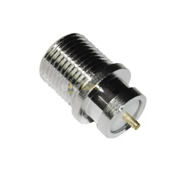
Close-up of a threaded coaxial panel-mount connector with a center contact and hexagonal body, illustrating the dimensions that must be defined for the panel cutout, mounting hardware and usable thread engagement.
Start with the enclosure, not the connector catalog.
Before selecting a part number, define what remains outside the cabinet and what remains inside. The outside may connect to an antenna jumper, feeder, filter or test cable. The inside may connect to a fixed semi-rigid cable, a flexible low-PIM jumper or a radio module.
Also record which side must remain replaceable.
A field technician may need to replace the external jumper without opening the enclosure. In another design, both the internal and external cable assemblies may need to be removable. These two service requirements lead to different connector structures.
The panel itself may perform one of two jobs.
A simple RF pass-through only separates two detachable cable assemblies. A structural mounting boundary must also carry cable torque, side load and vibration. Confusing these two jobs is a common enclosure-design mistake.
Define the service side before fixing the connector orientation
The front interface should remain accessible for mating, inspection and cleaning. Check the space needed to turn a coupling nut or operate a hand-screw or quick-lock mechanism.
Rear access matters just as much.
A compact connector may still be difficult to install if the technician cannot reach the mounting nut, solder joint or rear cable clamp. Adjacent connectors, fans, heat sinks and shielding walls often remove more working space than the enclosure drawing suggests.
The cable direction should also be decided early. Do not place the port first and assume the cable can be bent later.
Decide whether the panel carries cable weight
A heavy external jumper should not hang from the connector without additional support. Even when the mounting nut remains tight, cable leverage may distort the panel, rotate the connector body or load the rear termination.
Use a panel-supported bulkhead assembly when the enclosure is intended to carry external cable force. Add a cable clamp or bracket when that force is higher than the connector and sheet metal should reasonably carry.
The following selector provides a starting point.
| Installation condition | Recommended architecture |
| Detachable cable assemblies on both sides | Female-to-female feedthrough adapter |
| Fixed internal cable route | Cable-terminated bulkhead connector |
| Heavy external jumper | Reinforced panel mount with separate cable support |
| Frequent field replacement | Feedthrough adapter |
| Minimum number of RF interfaces | Direct cable termination |
| Outdoor sealed enclosure | Qualified sealed bulkhead assembly |
| Rear cable not yet selected | Freeze the cable architecture before machining |
This is a design selector, not a substitute for the supplier’s drawing. The exact mounting method and dimensional limits still depend on the selected SKU.
For a broader explanation of the interface itself, coupling methods and 50-ohm requirements, refer to the TEJTE 4.3-10 connector guide.
How Do You Separate a Cable-Terminated Bulkhead From a Feedthrough?
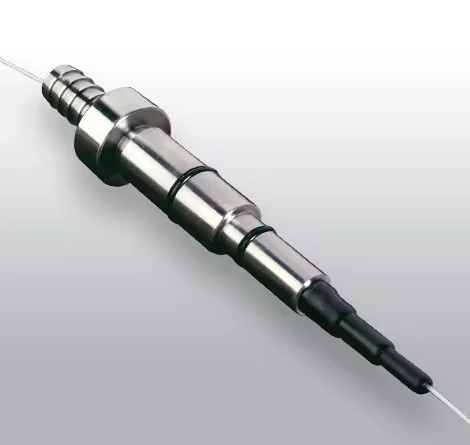
Metal bulkhead feedthrough assembly with cable terminations extending from both ends, used to illustrate the structural difference between a cable-terminated bulkhead connector and a female-to-female feedthrough adapter.
The two products may look similar from the outside.
Both can present a female 4.3-10 interface at the panel. Both may use a threaded body, locknut, flange or anti-rotation feature. The difference is behind the enclosure wall.
A cable-terminated bulkhead connects directly to coaxial cable at the rear.
Front 4.3-10 Interface Panel Mounting Body Direct Cable Termination A feedthrough adapter provides a complete connector interface on both sides.
External 4.3-10 Male Cable Front Female Interface Panel Rear Female Interface Internal 4.3-10 Male Cable
Use a cable-terminated bulkhead for a fixed internal architecture
This structure is often suitable when the rear cable route is defined at the factory.
Examples include an RG401-compatible semi-rigid cable entering a compact RF module, a factory-installed low-PIM coaxial lead or an internal jumper that is not expected to be replaced in the field.
Removing one detachable mating pair can simplify the RF path. It can also reduce one potential source of mismatch, contamination and PIM.
The trade-off is serviceability.
If the rear termination fails, the technician may need to remove the complete connector-and-cable assembly. A soldered semi-rigid termination can be especially difficult to repair inside a populated cabinet.
Use a feedthrough when modular replacement matters
A 4.3-10 female-to-female bulkhead adapter allows the external and internal cable assemblies to be handled as separate parts.
That helps when:
- external jumpers are regularly replaced;
- different internal cable lengths are used across several cabinet versions;
- cable assemblies are tested and stocked separately;
- technicians need to isolate a fault without removing the panel connector;
- the enclosure is part of a modular radio or DAS architecture.
The extra interface is not free. It adds another mated junction and requires additional rear clearance.
| Requirement | Cable-terminated bulkhead | Female-to-female feedthrough |
| Rear connection | Direct coax termination | Detachable RF interface |
| Number of mated junctions | Fewer | More |
| Field replacement | More difficult | Easier |
| Factory assembly | Usually preferred | Optional |
| Rear space | Controlled by cable bend | Controlled by connector and cable |
| PIM risk points | Fewer junctions | Additional mating pair |
| Inventory flexibility | Lower | Higher |
| Typical use | Fixed RF architecture | Modular enclosure |
| Calculated clearance margin | ___ mm | Maximum ___:1 |
| Machining decision | Pass / Redesign | Maximum ___ dB |
| Installed PIM | PIM analyzer | Maximum ___ dBc |
| Post-load variation | Repeat test | Maximum allowed change |
| Seal inspection | Visual or environmental test | Pass / Fail |
| Final decision | Combined review | Approve / Reject |
A buyer should therefore avoid using “4.3-10 panel connector” as the complete RFQ description. It does not tell the supplier which structure is required.
Which Panel Dimensions Must Be Frozen Before Machining?
A panel opening should never be released based on a catalog photograph.
Bulkhead connector bodies vary. The cutout may be round, keyed or flattened for anti-rotation. Some designs use a threaded mounting body. Others use a flange and separate mounting holes. Even products with the same front interface may require different cutouts.
Some 4.3-10 bulkhead designs use mounting threads such as M20 × 1, but this must not be treated as a universal dimension. The selected product drawing remains the controlling document.
Lock the hole and anti-rotation geometry
The panel drawing should state:
- finished hole diameter;
- machining tolerance;
- anti-rotation flat or keyway dimensions;
- flange-hole pattern, where applicable;
- mounting thread;
- washer and locknut contact diameter;
- edge deburring requirement;
- coating or paint restrictions around the mounting area.
A circular hole may be easy to machine, but it may allow the connector body to rotate while the front cable is being tightened. That rotation can transfer torque into the rear cable termination.
An anti-rotation flat is useful only when its tolerance matches the body correctly. Too much clearance defeats the feature. Too little clearance can damage plating or prevent installation.
Define the panel-thickness range
The connector must provide enough usable thread after the panel, gasket, washer and nut are installed.
Do not check panel thickness by itself. Check the complete stack:
Panel+ Gasket+ Washer+ Locking Feature+ Required Nut Engagement A thicker panel may reduce thread engagement. A thinner panel may allow the body to project too far or make the seal difficult to compress consistently.
Front and rear projection should also be measured from the correct reference plane. “Overall length” is not enough for enclosure design.
Calculate rear clearance before placing internal hardware
Use the following screening calculation:
Rear Clearance Margin =Available Rear Depth− Rear Connector Projection− Cable Bend Allowance− Tool Clearance A negative result means the architecture does not fit.
A small positive result may still be risky if production tolerances, connector rotation or assembly access have not been considered.
Freeze this worksheet before ordering machined panels. Changing a cable assembly is usually cheaper than reworking a cabinet batch.
Can the Panel Carry the Cable Load Without Distorting the RF Joint?
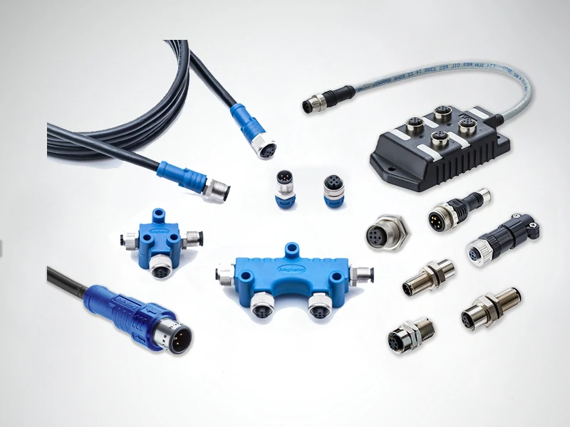
Industrial connector system containing cable assemblies, panel-mounted ports, junction modules, splitters and inline adapters, demonstrating why sealing, cable routing and installed performance must be assessed across the complete assembly rather than at a single connector interface.
Continuity does not reveal mechanical stress.
The center conductor may remain electrically connected while the panel flexes, the mounting nut loosens or the rear termination is gradually loaded. Low-PIM installations are particularly sensitive to unstable metal contact.
A basic mechanical screening calculation is:
Mounting Moment = Applied Force × Lever Distance M = F × d
The force may come from cable weight, technician handling or side pull. The lever distance is measured from the panel mounting point to the location where that force acts.
The formula is simple. Real cable loading is not.
Cable stiffness, connector orientation, vibration and service loops can create changing forces rather than one constant load.
Identify high-risk installations
Mechanical risk increases with:
- heavy feeder or jumper cable;
- unsupported horizontal routing;
- a long adapter stack outside the panel;
- repeated cable movement;
- thin sheet-metal walls;
- door-mounted connectors;
- vibration;
- a rear cable bent directly against the termination;
- a service loop hanging from the port.
Move cable weight away from the RF joint.
External clamps, internal tie-downs, short flexible sections and reinforced mounting plates are usually more effective than simply applying more torque to the connector nut.
Prevent body rotation
During first-article inspection, mark the connector body and panel. Mate and unmate the cable several times, then check whether the marks have shifted.
Also inspect:
- locknut retention;
- panel deformation;
- anti-rotation engagement;
- twisting of the rear cable;
- movement after representative cable loading.
A useful screening score is:
Panel Load Risk =Cable Weight+ Lever Length+ Cable Stiffness+ Vibration+ Panel Flexibility+ Missing Strain Relief Score each factor from 1 to 5.
- 6–10: Standard mounting may be acceptable.
- 11–18: Reinforce the panel and add cable support.
- 19–30: Redesign the cable boundary.
This score is an engineering screening tool, not an industry standard. It helps teams identify which installations deserve a mechanical test before production.
Can the Installed Bulkhead Preserve Low-PIM Performance?
A low-PIM connector does not guarantee a low-PIM enclosure.
The installed result may be affected by the connector termination, panel contact, mounting hardware, cable side load, contamination, damaged plating and nearby loose metal parts.
A female-to-female feedthrough adds another mating pair. A cable-terminated design removes that pair but introduces a permanent rear termination. Either architecture can work. Both must be evaluated in the actual installation.
The 4.3-10 interface is standardized under IEC 61169-54, and commercial product families are widely developed for low-PIM wireless infrastructure. The complete assembly result, however, still depends on the specific part, installation and test conditions.
Test in the real panel
A useful qualification sequence is:
- Measure the connector or assembly in the free state.
- Install it in the production-representative panel.
- Repeat the measurement after tightening the mounting hardware.
- Attach the specified external and internal cables.
- Apply representative cable load.
- Remate the front interface.
- Repeat the test after controlled tapping or vibration where relevant.
- Record the worst value, not only the final value.
If PIM changes after installation, inspect the panel contact area before rejecting the connector.
Paint, burrs, uneven gasket compression and loose washers can create unstable mechanical contact. Side load may also move the interface enough to change the result.
Write measurable PIM conditions into the RFQ
“Low PIM” is not an acceptance criterion.
Specify:
- maximum PIM in dBc;
- carrier frequencies;
- power per carrier;
- intermodulation order;
- forward or reverse test;
- test duration;
- panel material and thickness;
- cable type and bend condition;
- mounting torque;
- pass/fail treatment of unstable readings.
A supplier cannot reproduce a PIM result when the test conditions are missing.
Which Rear-Side Cable Path Fits the Enclosure?
The rear cable is part of the connector decision.
A product described as a 4.3-10 bulkhead connector for RG401 should not be approved only because RG401 appears in the title. Confirm the actual cable construction, outer diameter, dielectric dimensions and termination method against the supplier’s drawing.
Different semi-rigid cables can look similar while requiring different preparation dimensions.
Use semi-rigid cable when geometry must remain fixed
Semi-rigid cable is useful for factory-defined routes inside filters, radio modules and compact RF assemblies.
Its formed shape can provide repeatable routing. It also avoids a flexible cable moving against nearby components.
The limitations are practical:
- bend tooling may be required;
- rebending can damage the cable;
- soldering heat must be controlled;
- repair inside the enclosure may be difficult;
- the first bend cannot begin arbitrarily close to the connector;
- production fixtures may be needed to maintain geometry.
Use flexible coax when service access matters
Flexible coax is often better for offset modules, door-mounted panels and equipment that must be removed for maintenance.
It can also isolate the connector from vibration better than a rigid route.
Flexibility does not mean the cable can be folded immediately behind the connector. A tight first bend loads the termination, changes cable geometry and may reduce assembly repeatability.
Specify:
- minimum straight exit length;
- minimum bend radius;
- first clamp position;
- allowed service-loop size;
- areas where the cable must not rub;
- routing during RF acceptance testing.
The TEJTE RG cable guide provides a broader comparison of coaxial cable size, attenuation, flexibility and connector compatibility. For a bulkhead design, apply those cable factors specifically to the space and loading behind the panel.
How Should Water and Contamination Be Blocked at the Panel?
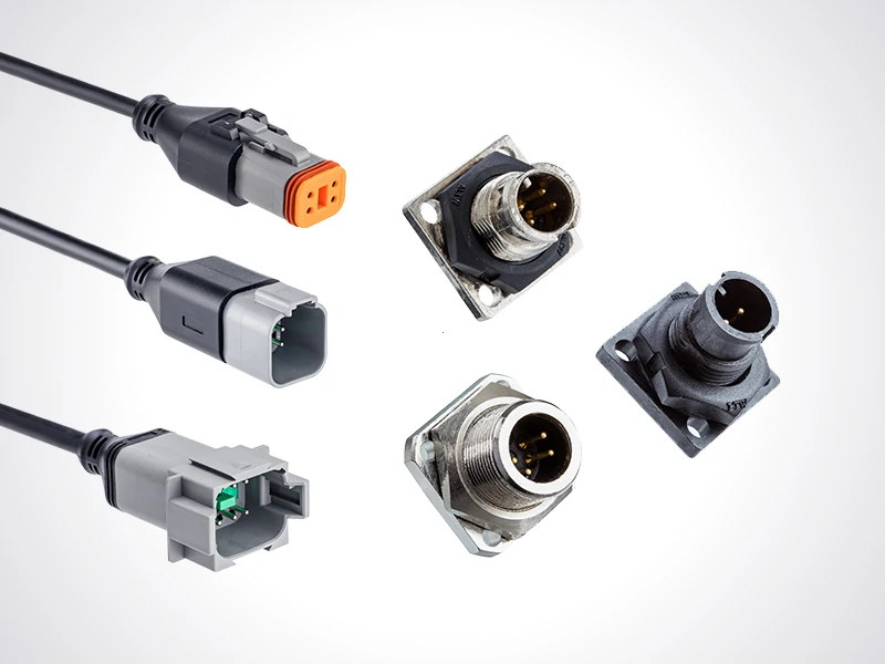
Collection of sealed cable connectors and circular panel-mount receptacles in several housing configurations, illustrating how connector orientation, mounting style, cable support and environmental protection affect the completed enclosure design.
An IP-rated mating interface does not automatically make the enclosure penetration waterproof.
The complete sealing path includes:
- the mated front interface;
- the connector body;
- the connector-to-panel joint;
- the mounting thread;
- the gasket or O-ring;
- the rear cable termination;
- the enclosure wall.
Each point can fail independently.
Some commercial 4.3-10 product families offer environmentally protected versions for wireless infrastructure. For an example of series-level options, see the Amphenol RF 4.3-10 connector reference. The selected SKU and complete installation still need separate verification.
Separate interface sealing from panel sealing
Ask two different questions:
- Is the mated connector interface protected?
- Is the hole through the enclosure protected?
A front connector may be sealed when properly mated, while water still passes between the bulkhead body and panel.
Paint texture, scratches, burrs and uneven sheet metal can prevent consistent gasket compression. Reassembly can also damage an O-ring that passed the original test.
Control the mounting surface
The drawing should define:
- gasket location;
- required surface finish;
- panel flatness;
- allowable coating thickness;
- compression range;
- mounting torque;
- whether the seal is reusable;
- replacement instructions after maintenance.
Avoid upward-facing joints where water can collect. Add drip loops and external cable support. The rear side should also be protected from condensation, especially in outdoor cabinets with changing internal temperature.
Use this audit before approving an outdoor design:
Front Mating Interface: Verified / Not Verified Bulkhead-to-Panel Seal: Verified / Not Verified Mounting Thread Seal: Defined / Undefined Rear Cable Termination: Protected / Exposed Panel Surface: Approved / Not Approved Water Pooling Risk: Low / Medium / High Condensation Control: Defined / Undefined Complete Assembly Rating: Verified / Not Verified Outdoor Approval: Pass / Reject
What Evidence Must the Installed First Article Produce?
A first article should be assembled in the real panel, not only checked against a loose connector drawing.
Dimensional inspection comes first.
Confirm the hole, panel thickness, front projection, rear projection, nut engagement, anti-rotation feature, connector alignment and cable clearance. Adjacent ports should also be populated when their spacing may affect tool access.
Check basic electrical integrity before RF testing
Use a digital multimeter or suitable resistance equipment to verify:
- center-conductor continuity;
- shield continuity;
- center-to-shield isolation;
- intermittent contact during light cable movement.
These checks cannot confirm RF performance. They are still useful because they can find assembly errors before VNA or PIM test time is spent.
Measure the installed RF path
Record:
- frequency range;
- VNA calibration method;
- calibration reference planes;
- return loss;
- VSWR;
- insertion loss;
- worst frequency;
- cable configuration;
- sample number;
- panel configuration.
The calibration plane matters. A measurement that includes two long test cables and several adapters cannot be compared directly with a connector-level datasheet limit unless the fixture effects are removed or consistently controlled.
Repeat the tests after mechanical loading
Apply the cable arrangement expected in service.
Flex the rear cable within its allowed routing range. Attach the specified external jumper. Remate the front interface and retighten the mounting hardware according to the approved procedure.
Then repeat continuity, VNA and PIM testing.
Do not approve only the best-performing sample. Record the sample count and worst result.
Build the Purchase Drawing Around the Panel Stack
A purchase description should identify the architecture immediately.
For a direct cable termination:
4.3-10 Female Bulkhead Connector for RG401-Compatible Semi-Rigid Cable 50 Ohm Low-PIM Application
For a feedthrough:
4.3-10 Female-to-Female Bulkhead Feedthrough Adapter 50 Ohm Panel-Mount Design
“4.3-10 bulkhead adapter” alone is not enough.
Separate RF requirements from installation requirements
RF requirements may include:
- 50-ohm impedance;
- operating frequency;
- maximum VSWR;
- minimum return loss;
- maximum insertion loss;
- power requirement;
- PIM limit and test conditions.
Installation requirements may include:
- panel cutout;
- panel-thickness range;
- mounting method;
- nut and washer arrangement;
- anti-rotation feature;
- mounting torque;
- rear cable type;
- sealing method;
- mechanical load;
- environmental rating.
Combining all of this under “frequency range” creates an incomplete RFQ.
When Is a Bulkhead Connector the Wrong Architecture?
A panel connector is not automatically the cleanest solution.
Use a cable gland when the coaxial cable should pass continuously through the enclosure and no detachable RF interface is needed. This removes a mating pair and may reduce the number of possible PIM and sealing points.
Use a short pigtail when panel alignment cannot be controlled. A flexible lead may be safer for moving doors, thin enclosure walls, offset internal modules or high-vibration equipment.
Use a feedthrough when both cable assemblies must remain replaceable.
Avoid the panel boundary completely when it adds:
- an unnecessary mating interface;
- more insertion loss;
- an extra PIM risk point;
- additional sealing work;
- more inventory;
- no real maintenance benefit.
The connector should solve an enclosure problem. It should not create a new one.
FAQ
Is a 4.3-10 bulkhead connector always female on the front?
No. Female front interfaces are common because many feeder and jumper assemblies use a male cable connector, but the required gender must be selected from the actual mating part. Do not infer gender from the term “bulkhead.” Check the interface drawing, contact configuration and equipment-side cable before releasing the BOM.
Is a bulkhead connector the same as a female-to-female feedthrough?
No. A cable-terminated bulkhead attaches directly to coaxial cable behind the panel. A female-to-female feedthrough provides a detachable 4.3-10 interface on both sides. The feedthrough is easier to service, while the cable-terminated design can reduce the number of mated RF junctions.
Can the mounting nut support a heavy external feeder?
Not in every installation. The mounting nut, anti-rotation feature, panel thickness and cable support must be evaluated together. A heavy or stiff cable can create significant leverage at the panel. Use a separate clamp or bracket when the cable load could flex the panel or twist the rear termination.
Does an IP-rated 4.3-10 interface make the panel opening waterproof?
No. Interface sealing and panel sealing are different. The gasket, connector body, mounting thread, enclosure surface and rear cable termination must also be protected. The environmental rating should apply to the complete installed assembly under defined test conditions, not only to the connector series.
Why can PIM increase after installation?
Panel stress, loose mounting hardware, contamination, damaged plating, cable side load and nearby unstable metal contact can change the PIM result. Test the connector after it is mounted in the production panel and after representative cables are attached. Record the worst reading during the defined test period.
When is an RG401 bulkhead connector preferable to a feedthrough adapter?
It may be preferable when the internal route is fixed, factory assembly is available and reducing one detachable mating interface is more important than field replacement. Confirm the exact cable compatibility, termination process, bend tooling and repair method before approving the design.
What should be checked before approving the panel drawing?
Confirm the cutout, panel-thickness range, mounting thread, anti-rotation feature, front and rear projections, nut engagement, gasket stack, cable bend clearance, tool access, connector spacing and strain relief. The drawing should also reference the installed RF, PIM and environmental acceptance requirements.
Final Specification Note
The most expensive bulkhead error is often not the connector price.
It is a machined panel that fits the wrong body, a rear cable that cannot bend inside the enclosure, or a low-PIM part that was never tested after installation.
Before ordering, send the supplier the front mating interface, rear architecture, cable type, panel cutout, panel thickness, available rear depth, mechanical-load condition, sealing requirement and installed RF acceptance limits.
That information allows the supplier to confirm whether a cable-terminated connector, female-to-female feedthrough or another panel architecture is the safer choice.
For custom RF enclosure projects, TEJTE can review connector drawings, cable compatibility, mounting dimensions and first-article test requirements before production. The useful starting point is a complete panel stack and cable route—not only a connector name.
