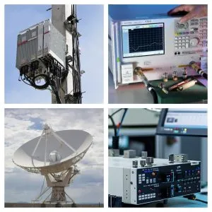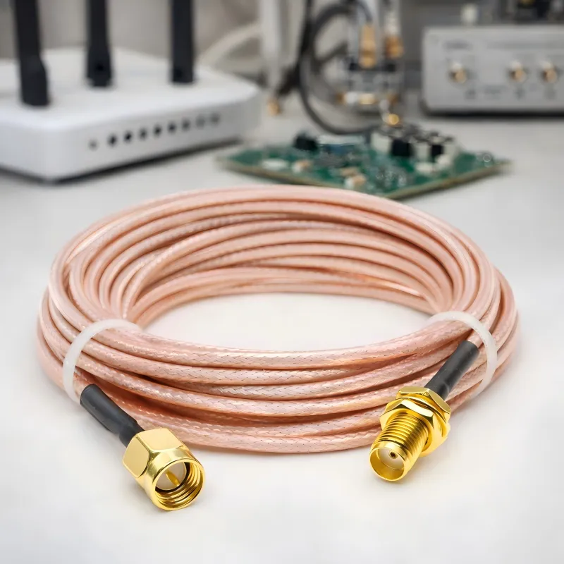
SMA Adapter Cable for RF Systems
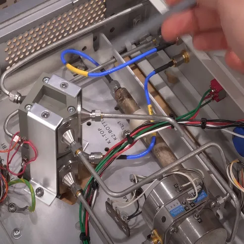
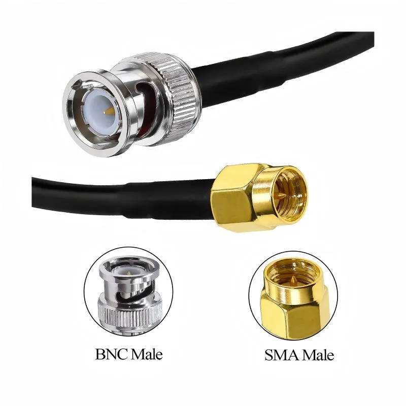
A small connector mismatch usually shows up late. The radio module is already selected. The enclosure drawing is almost finished. Someone on the bench connects the RF output to a test instrument and notices the ports don’t match. SMA on the device. BNC on the instrument. Or sometimes the port sits recessed behind a panel wall and the rigid adapter that “should work” simply doesn’t reach.