
A coax cable assembly may work perfectly on the test bench and still fail to meet the requirements of the finished RF system. The cable is longer than the prototype, the antenna has moved outdoors, or a different connector has been added to simplify installation. Each change seems minor until the measured insertion loss or return loss no longer matches the original design.
The problem often starts before the cable is ordered. A buyer requests RG58 because it appears in an earlier bill of materials. An engineer selects a thinner cable to fit a crowded enclosure. Neither decision is necessarily wrong, but neither confirms that the finished signal path will meet its electrical and mechanical requirements.
A more useful approach is to define the application first, then evaluate impedance, operating frequency, cable length, attenuation, construction, connector compatibility, and installation conditions together. The objective is not simply to find a coax cable with suitable specifications. It is to approve a cable configuration that works in the actual equipment.
How Should the Application Define the Coax Cable First?
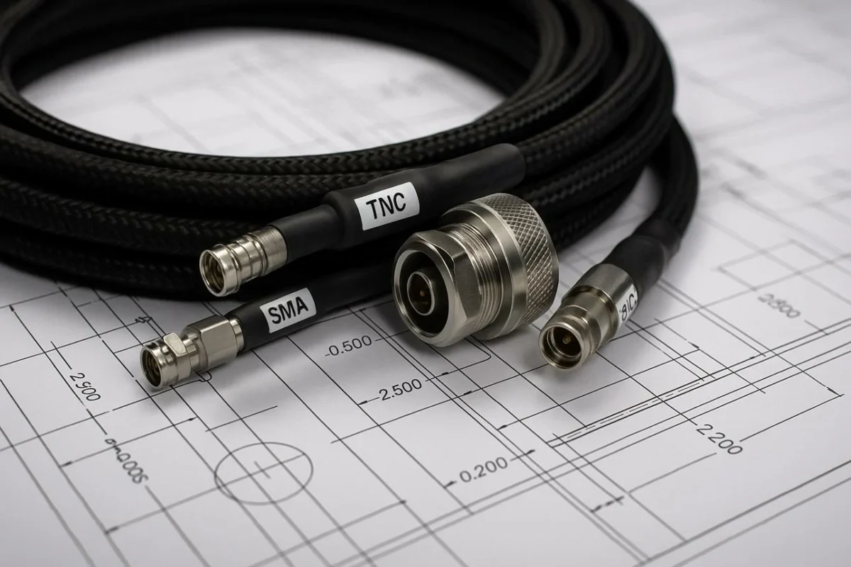
A cable that performs well inside a stationary test fixture may be unsuitable for a moving equipment assembly. The same is true of a low-loss outdoor feeder installed inside a compact device. Its electrical characteristics may be acceptable, while its diameter and stiffness create mechanical problems.
Start with the signal path rather than an RG designation.
Separate Test Jumpers, Antenna Feed Lines, and Internal RF Links
Different applications place different demands on coax cables.
A laboratory test jumper may be connected and disconnected frequently. Connector durability, phase stability where required, flexibility, and measurement repeatability can matter as much as nominal attenuation. A cable intended for occasional static measurements does not automatically qualify for repeated flexing.
An antenna feed line presents a different problem. Cable length and operating frequency can make attenuation a significant part of the RF link budget. Outdoor installations also introduce moisture, sunlight, temperature changes, and mechanical loading.
Internal RF links are often shorter, but available space is limited. A small coaxial cable may fit between circuit boards and modules where a larger feeder cannot. However, the smaller construction can introduce greater attenuation per meter, particularly as frequency increases.
Vehicle radio connections add vibration, routing constraints, and possible abrasion. Broadcast and video systems may introduce a different impedance requirement altogether.
The application therefore determines which specifications deserve priority.
Record Frequency, Distance, Power, and Movement
Before comparing cable models, record four basic operating conditions: frequency, installed length, RF power, and mechanical movement.
Frequency affects attenuation and the required performance of the cable-to-connector transition. A cable evaluated at 100 MHz cannot be assumed to deliver the same loss per meter at 2.4 GHz or 6 GHz.
Length matters because attenuation accumulates along the transmission path. A short internal jumper may tolerate a cable construction that becomes impractical over a longer antenna feed.
Power handling needs separate attention. A cable suitable for low-power receive signals may not be appropriate for a higher-power transmitter. Actual limits depend on frequency, cable construction, temperature, impedance matching, and installation conditions.
Movement is easy to overlook. A cable that bends during installation but remains fixed afterward has different requirements from one that flexes repeatedly during operation.
For procurement, these conditions should be included in the request for quotation rather than left for the supplier to infer from a cable model name.
Identify the Installation Environment Before Choosing Cable Size
Cable diameter is not merely a packaging detail.
A thicker low-loss coax cable may offer an electrical advantage but require more clearance, a larger bend radius, and additional mechanical support.
A cable described as suitable for RF transmission is not necessarily qualified for continuous outdoor exposure.
Industrial equipment may introduce oil, chemicals, vibration, or abrasion. The jacket and shielding construction should be evaluated against those conditions using the manufacturer’s actual specifications.
Build the Complete Path From Source to Load
The cable itself is only one part of the transmission path.
The radio output, cable, bulkhead connection, adapter, and antenna must be considered together. Every interface introduces a potential source of mismatch or additional insertion loss.
A connector may physically mate with the equipment while its impedance or electrical performance is unsuitable for the application.
This is also why a short cable assembly tested independently may produce different results after installation. The finished path includes components and transitions that were not present during the original measurement.
For further comparisons of common RG constructions, see TEJTE’s RG Cable Guide. The RG designation is a useful starting point, but the complete application requirements should control the final selection.
How Do 50Ω and 75Ω Systems Change the Cable Choice?
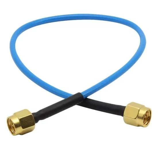
A blue coaxial RF cable assembly equipped with SMA connectors. Suitable for antenna connections, wireless communication equipment, RF modules, and electronic testing applications.
Impedance should be confirmed before comparing attenuation or cable diameter.
A 50 ohm coax cable is commonly used in RF communication equipment, antenna systems, and test instruments. A 75 ohm coax cable is common in television distribution, CATV, broadcast video, and certain signal distribution applications.
These are common applications, not universal rules. The equipment specification determines the required impedance.
Use System Impedance as an Early Filter
Consider two cables with similar outside diameters and connector appearances. One has a nominal characteristic impedance of 50Ω; the other is 75Ω.
They are not automatically interchangeable.
Connecting a 75Ω cable between a 50Ω source and a 50Ω load creates impedance discontinuities. These can cause reflections and affect the measured return loss, VSWR, and transmission response.
The practical rule is to check the entire path, not just the cable label.
| RF path component | Specification to confirm |
| Signal source | Nominal output impedance |
| Coax cable | Characteristic impedance |
| Connector | Interface impedance and compatibility |
| RF adapter | Impedance and operating frequency |
| Antenna or load | Nominal input impedance |
A mechanically compatible connector does not guarantee an electrically matched connection. Some connector families have different impedance versions, and mechanical compatibility varies by interface design.
Keep Source, Cable, Connector, and Load Impedance Consistent
For a nominal 50Ω RF system, the preferred configuration is generally a consistent 50Ω transmission path from source to load.
Where an impedance transition is intentional, it should be treated as part of the RF design rather than an undocumented cable substitution.
VSWR or return-loss measurements can help verify the finished assembly across its required operating band. A continuity test cannot establish impedance matching or acceptable high-frequency performance.
This distinction matters when approving production substitutions. Two coax cables may share the same impedance but differ substantially in attenuation, shielding, dimensions, and flexibility. Matching impedance is necessary for many RF systems, but it is not sufficient to approve the complete cable configuration.
How Much Cable Loss Can the RF Link Actually Tolerate?
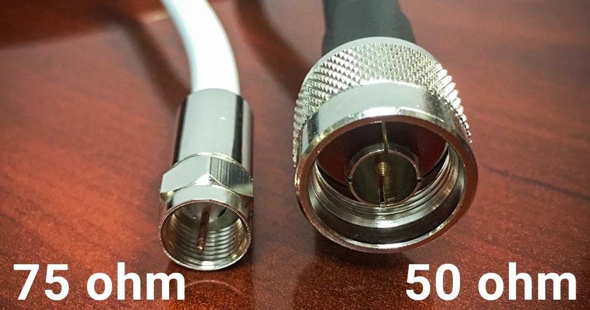
A close-up comparison of 50-ohm and 75-ohm coaxial connector configurations. These impedance options serve different applications, including RF communication, antenna systems, television distribution, and broadcast equipment.
Low loss sounds attractive, but it is not a useful specification until the operating frequency and installed cable length are known.
A cable may look acceptable in a datasheet because the attenuation number is quoted at a relatively low frequency. The same cable can become a much larger part of the link budget several GHz higher. For that reason, cable loss should be calculated at or near the actual operating band rather than taken from a convenient headline value.
Read Attenuation at the Required Frequency
Coax cable attenuation is normally published per unit length, such as dB/m or dB/100 ft, at several frequencies.
The comparison only makes sense when the candidates are evaluated under the same conditions.
If Cable A is listed at 100 MHz and Cable B is listed at 2.4 GHz, the two attenuation values cannot be used directly to decide which cable performs better at 2.4 GHz.
Check at least:
- operating frequency
- attenuation unit
- reference length
- test condition where specified
- exact manufacturer part number
This becomes especially important when procurement receives several quotations for what appears to be the same cable family. Two products carrying a similar RG designation can still differ in conductor construction, shielding, dimensions, jacket material, and measured attenuation.
Convert Published Attenuation Into Installed Loss
Suppose a cable is specified at 0.5 dB/m at the required frequency. A 0.3 m internal jumper contributes roughly 0.15 dB before connector effects are considered. At 8 m, the same cable contributes about 4 dB.
The cable did not change. The application did.
This is why a small flexible RF coax cable may be perfectly reasonable inside an enclosure but unsuitable as a long antenna feeder.
Account for Connector and Adapter Transitions Separately
Cable attenuation is not the entire path loss.
The interface term may include connectors, adapters, bulkheads, transitions, and other passive components in the RF path.
Exact values should come from relevant component data or measurement rather than a universal allowance.
Each extra transition may be electrically acceptable on its own, yet the accumulated result can consume margin that was originally reserved for the cable.
For sensitive designs, evaluate the finished configuration with the actual connectors and adapters rather than assuming the bare cable attenuation represents total insertion loss.
Compare Low-Loss Cable Against Added Diameter and Stiffness
Lower attenuation often comes with a mechanical cost.
A larger low-loss coax cable may introduce:
- greater outside diameter
- more weight
- larger minimum bend radius
- higher connector size
- greater stress on equipment ports
- more difficult routing through enclosures
A 0.5 dB improvement is useful only if the new cable can actually be installed without creating another failure point.
For short RF jumpers, the difference between two cable types may be small enough that flexibility and connector support matter more. For a long antenna run, the loss saving can become much more significant.
The decision should therefore be based on total path margin rather than the label “low loss coax cable.”
When Does Cable Construction Matter More Than the RG Name?
An RG number is useful for identifying a general cable family, but it should not be treated as a complete engineering specification.
That shortcut causes procurement problems because suppliers may offer cables with similar dimensions or nominal impedance while using different materials and construction.
Compare Solid and Stranded Center Conductors
A solid center conductor can provide stable geometry and is common in many fixed installations. A stranded center conductor generally provides better flexibility where repeated handling or tighter routing is required.
Neither construction is automatically superior.
The selection depends on how the cable will be installed, terminated, and moved.
A test jumper that is handled every day has a different mechanical requirement from a fixed antenna feed line that is installed once and left in place.
Evaluate Dielectric Construction Alongside Attenuation
The dielectric is part of the cable’s electrical geometry. Its material and dimensions influence characteristic impedance, propagation behavior, and loss.
For sourcing work, the practical point is simple: do not substitute a cable based on outside diameter alone.
Two cables can look nearly identical from the outside while using different dielectric dimensions or materials internally.
If the assembly is already qualified, changing the cable manufacturer or part number should trigger a specification comparison rather than an automatic substitution.
Compare Foil, Braid, and Multi-Layer Shielding
Shield construction affects more than appearance.
A braid can provide mechanical flexibility and a useful conductive termination surface. Foil can improve shielding coverage but behaves differently during stripping and termination. Some cables combine foil and braid or use multiple shielding layers when enhanced shielding is required.
The correct construction depends on EMI requirements, flexibility, termination method, and assembly process.
A supplier should therefore identify the actual shielding construction rather than simply state “shielded coax cable.”
| Construction item | What to verify | Why it matters |
| Center conductor | Solid or stranded | Flexibility and termination |
| Dielectric | Material and diameter | Impedance and RF behavior |
| Shield | Braid, foil, multi-layer | Shielding and assembly process |
| Jacket | Material and rating | Environment and routing |
| Cable OD | Actual tolerance | Connector and installation fit |
The last row is easy to underestimate. Cable OD directly affects ferrule size, clamp fit, strain relief, and compatibility with the connector rear body.
Check Jacket Material Against the Actual Environment
For an indoor bench cable, jacket requirements may be relatively simple. Outdoor, industrial, and mobile applications need more scrutiny.
Check manufacturer data for the required temperature range and environmental exposure. If the cable will see sunlight, moisture, oils, chemicals, or abrasion, those conditions should be stated in the sourcing specification.
Do not assume that every black coax jacket is automatically suitable for outdoor use.
How Should Frequency Change the Cable Decision?
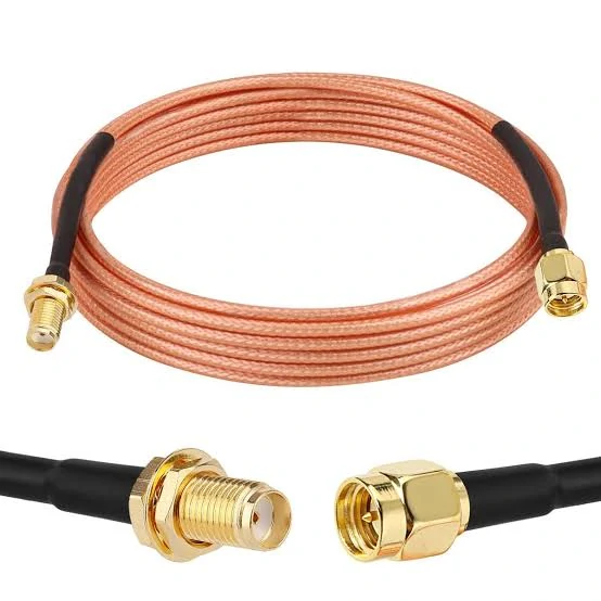
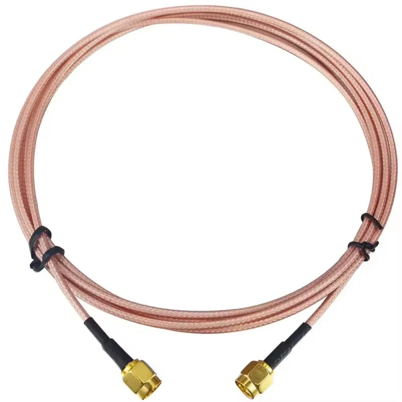
A braided coaxial cable assembly featuring SMA connectors at both ends. Designed for RF signal transmission, antenna connections, and electronic equipment.
Frequency exposes weaknesses that may stay hidden at lower bands.
A cable assembly that behaves acceptably at hundreds of MHz can show more loss or mismatch when moved into multi-GHz service.
Expect Attenuation to Increase as Frequency Rises
Cable attenuation generally increases with frequency, so a single loss figure should never represent the entire operating range.
For a system covering a wide band, compare attenuation near the upper operating frequency as well as at any critical test points.
The same rule applies when comparing candidate cables:
Same frequency → same length → same attenuation unit → same reference condition.
Without that discipline, a cable comparison table can look precise while producing the wrong design decision.
Watch the Cable-to-Connector Transition at Higher Frequencies
At higher frequencies, the connector transition and termination quality deserve more attention.
Incorrect center conductor preparation, poor braid contact, damaged dielectric, excessive soldering heat, or unsuitable connector geometry can degrade an otherwise acceptable cable.
The finished assembly should therefore be treated as one RF component.
Cable data tells you what the transmission line can potentially deliver. The assembled cable, connectors, bends, and installation determine what the system actually receives.
How Can You Balance Cable Diameter, Flexibility, and Bend Space?
Lower loss is useful only if the cable can be installed without creating mechanical problems.
A larger coax cable normally needs more routing space and a larger bend radius. It may also place more load on a small SMA, MMCX, or PCB-mounted connector. That can turn an electrical improvement into a mechanical reliability problem.
Calculate the Real Routing Space Before Selecting a Larger Cable
Do not compare cable OD only against the straight opening in the enclosure. Check the complete route:
- entry hole or gland
- connector rear body
- bend after termination
- nearby PCB components
- cable tray or conduit
- strain-relief area
A cable may pass through an opening but still be impossible to bend into its final position.
Static bend requirements should also be separated from repeated flexing. A cable that can tolerate one installation bend is not automatically suitable for a moving arm, rotating fixture, or frequently handled test lead.
For heavy feeder cable connected to a small RF port, consider mechanical support or a short flexible jumper.
This keeps the heavy cable from applying continuous force directly to the equipment connector.
How Should the Connector Influence the Final Cable Choice?
The connector should not be selected from the front interface alone.
Two SMA male connectors may mate with the same equipment port while having completely different rear dimensions for RG58, RG316, 1.13 mm cable, or another coax construction.
Confirm the Equipment Interface Before Freezing the Cable
First confirm the required mating interface:
- SMA
- BNC
- TNC
- N-Type
- another specified RF interface
Then check whether the connector is available for the exact selected cable.
Rear termination compatibility should include cable OD, dielectric diameter, center conductor size, shielding construction, ferrule dimensions, and assembly method.
A connector made for RG316 should not be substituted automatically for RG58 simply because both are 50Ω cables.
This is a common sourcing mistake: the front interface matches, but the rear termination does not.
Avoid Building an Adapter Stack Without Checking the Penalty
A growing number of adapters may indicate that the original cable assembly should be redesigned.
If the path becomes:
Cable → Adapter → Adapter → Different Cable
a purpose-built mixed-connector cable assembly may be cleaner and easier to control in production.
Fewer transitions can also simplify inspection, labeling, and BOM management.
How Can You Score Coax Cable Candidates Before Ordering?
A useful cable comparison should place the project requirement beside the candidate cable instead of comparing catalog numbers in isolation.
Coax Cable Selection Scorecard
| Selection field | Project requirement | Candidate cable | Status |
| Impedance | 50Ω / 75Ω | Confirmed value | Pass / Review |
| Frequency | Required band | Rated / tested range | Pass / Review |
| Length | Installed length | Actual length | Pass / Review |
| Maximum cable loss | dB limit | Calculated loss | Pass / Review |
| Cable OD | Maximum available space | Actual OD | Pass / Review |
| Flexibility | Static / repeated flex | Cable construction | Pass / Review |
| Shielding | Standard / enhanced | Actual shield | Pass / Review |
| Environment | Indoor / outdoor / industrial | Jacket suitability | Pass / Review |
| Connector fit | Required interfaces | Compatible termination | Pass / Review |
| RF power | Project requirement | Verified rating | Pass / Review |
This matrix is useful because it exposes trade-offs early. A candidate may pass the RF loss requirement but fail on routing space. Another may fit mechanically but consume too much link margin.
How Can You Validate the Cable Before Locking the Design?
The final BOM should contain more than “RG58 coax cable.”
That level of detail reduces substitution risk during repeat production.
Build the First Assembly With the Intended Connectors
Prototype the complete assembly rather than testing bare cable alone.
The connector termination can influence RF behavior through center-pin alignment, braid contact, dielectric preparation, soldering, crimp quality, and transition geometry.
Measure the finished assembly across the required operating band. Depending on the project, useful checks may include:
- insertion loss / S21
- return loss / S11
- VSWR
- continuity
- insulation resistance
- mechanical pull or flex inspection
RF measurements should be performed under defined test conditions and compared against agreed acceptance criteria.
The sample should also be evaluated in a routing condition close to the final installation. Tight bends, strain, vibration, or outdoor exposure can matter even when the bench sample looks good.
Once approved, freeze the cable–connector combination instead of allowing undocumented substitutions during production.
FAQ
Can two 50 ohm coax cables have very different loss?
Yes. Matching impedance does not mean matching attenuation. Conductor size, dielectric, shielding, frequency, and cable diameter can produce significantly different loss.
Does the correct coax cable guarantee good VSWR?
No. VSWR depends on the complete path, including cable, connectors, adapters, terminations, antenna, and load.
Should I select the cable or connector first?
Define the application and cable requirements first, then select a connector whose mating interface fits the equipment and whose rear termination fits the exact cable.
Why should the exact cable part number appear in the BOM?
Because cables with similar family names can differ in attenuation, shielding, dimensions, jacket material, and termination compatibility.
When is a low-loss coax cable upgrade worth it?
When the recovered RF margin justifies the added diameter, stiffness, weight, installation difficulty, and connector requirements.