
A 20 dB attenuator can be electrically correct and still be installed in the wrong place.
That happens more often than expected in RF test setups. A signal generator may produce more power than the next instrument should receive, so an engineer adds an RF attenuator somewhere in the coaxial path. The connector fits, the displayed level drops, and the setup appears safe.
But the actual result depends on where the attenuator sits, which reference plane matters, how much attenuation is really required, and whether cable or adapter losses have already reduced the signal.
Before comparing SMA attenuator models or power ratings, define the signal path first.
Where Should an RF Attenuator Sit in Your Signal Path?
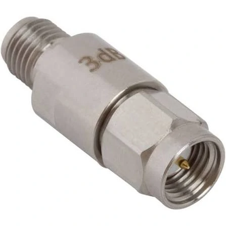
3 dB fixed SMA RF attenuator for reducing signal power in coaxial RF systems while maintaining a compact inline connection for test, measurement, and wireless applications.
Start by writing the RF path in one line.
Those two setups may use the same connector family and even the same nominal attenuation value, but the job of the attenuator is different.
Identify the RF Source, Load, and Measurement Objective
An attenuator placed after a signal generator may be used to reduce the stimulus reaching a receiver or DUT. An attenuator installed before a spectrum analyzer or power meter may instead be there to keep the instrument input below a safe level.
That distinction matters.
Suppose a transmitter produces +30 dBm while the measurement instrument should receive no more than +10 dBm. The basic requirement suggests at least 20 dB of level reduction before the sensitive input.
Move that attenuator to another point in the system and the measurement reference changes. Cable loss, adapters, splitters, filters, and other RF components between the attenuator and instrument can all affect the level that actually reaches the port.
The connector comes later.
Separate Level Reduction From Impedance Matching
A normal 50-ohm coaxial attenuator is primarily used to reduce RF signal level while operating in a system with the impedance for which it was designed.
It should not be treated as a universal impedance converter.
Adding a 50-ohm attenuator between two badly mismatched devices may sometimes reduce the effect of reflections seen elsewhere in a chain, but it does not turn an arbitrary source impedance into an arbitrary load impedance.
If the source, attenuator, and receiving equipment are intended for a 50-ohm system, confirm that specification across the complete path.
This is especially relevant in purchasing. A BOM description such as “10 dB SMA attenuator” leaves out information the supplier may actually need. At minimum, the intended impedance and operating frequency should also be defined.
Locate the Attenuator Before Evaluating Connector Gender
Mechanical convenience often drives the wrong decision.
An engineer sees an SMA female instrument port and immediately searches for an SMA male-to-female attenuator. That may eventually be the correct configuration, but first confirm where the device must sit.
An attenuator mounted directly on an analyzer input can protect that port and establish a convenient measurement point. In another setup, placing it closer to the RF source may be more appropriate because it reduces the level before the signal passes through downstream components.
The difference can become significant when the coaxial cable is long or when several adapters are involved.
Adapter stacks also deserve attention. A series of adapters may solve a gender mismatch on the bench, but every additional RF interface introduces another mechanical and electrical discontinuity. At higher frequencies, that can complicate the loss and mismatch budget.
How Many Decibels of Attenuation Do You Actually Need?
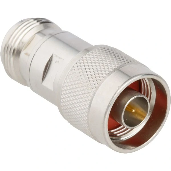
N-Type coaxial RF attenuator designed for stable signal reduction in 50-ohm RF systems, suitable for antennas, RF test equipment, communication systems, and coaxial signal paths.
Do not select 3 dB, 10 dB, or 20 dB because those values are common catalog options.
Calculate the required reduction from the signal limits.
Calculate Attenuation From Input and Target Output Power
Again, the required reduction is 20 dB.
The calculation is simple. The selection around it is not.
Cable loss, attenuator tolerance, frequency response, instrument accuracy, and other components in the RF path can shift the real output away from the theoretical value.
Convert 3 dB, 6 dB, 10 dB, and 20 dB Into Power Ratios
A frequent mistake is treating decibels like a linear percentage.
They are logarithmic.
For an ideal attenuator, the approximate power remaining at the output is:
| Nominal Attenuation | Output Power Relative to Input | Practical Interpretation |
| 3 dB | 50.10% | About half the input power remains |
| 6 dB | 25.10% | About one quarter remains |
| 10 dB | 10% | One tenth remains |
| 20 dB | 1% | One hundredth remains |
A 20 dB attenuator therefore does not remove “20 percent” of the signal. Under ideal matched conditions, it reduces the transmitted power to about 1% of the input value.
That distinction becomes important when estimating both output level and the power the attenuator itself may need to dissipate.
Reserve Margin for Measurement and Component Tolerances
The calculated value should be treated as the starting point, not proof that any attenuator marked with that number will produce exactly the required result.
A nominal 10 dB RF attenuator can have attenuation tolerance. Its response may also vary across frequency. Test cables and adapters contribute additional insertion loss, while instrument amplitude accuracy adds another layer of uncertainty.
For sensitive measurements, specify the allowable output window rather than only the nominal attenuation.
Avoid Choosing Attenuation From Connector Type Alone
SMA, BNC, and N-Type describe interface families. They do not determine how many decibels of attenuation the RF path needs.
An SMA attenuator may be available in 3 dB, 6 dB, 10 dB, 20 dB, 30 dB, or other values. The correct number comes from the signal-level calculation.
Only after the attenuation requirement is known should the engineer narrow the selection by frequency, impedance, power handling, connector configuration, and mechanical installation.
When Should You Choose a Fixed or Variable Attenuator?
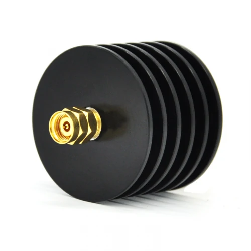
High-power SMA RF attenuator featuring a finned heat sink to dissipate RF power, suitable for RF testing, transmitter systems, laboratory equipment, and higher-power signal paths.
A fixed attenuator and a variable attenuator can produce the same nominal reduction at one operating point. That does not make them interchangeable in a test plan.
The real question is whether the signal level needs to remain stable or change repeatedly during testing.
Choose Fixed Attenuation for Stable RF Signal Reduction
A fixed attenuator is usually the simpler option when the required attenuation is already known.
Typical cases include protecting a spectrum analyzer input, reducing a known transmitter level, adding a permanent amount of attenuation in a test fixture, or maintaining a repeatable signal level between a source and DUT.
There is little adjustment ambiguity. A technician does not need to record a dial position or confirm a programmable setting every time the setup is rebuilt.
That simplicity is useful in production.
If a test station requires 10 dB of attenuation on every unit, a fixed 10 dB component can reduce setup differences between operators. The RF path is easier to document in the work instruction and easier to reproduce after cables or instruments are replaced.
Evaluate Variable Attenuation for Level Sweeps and Receiver Testing
A variable attenuator becomes more useful when the test itself requires different RF levels.
Receiver sensitivity testing is a typical example. The engineer may start with a relatively strong signal and increase attenuation in steps until packet errors, demodulation problems, or another receiver limit appears.
Replacing a fixed attenuator every time the level changes would be slow and may introduce additional mating wear or connection variation.
Variable designs can support faster level sweeps, but buyers should look beyond the total range.
A specification such as “0–30 dB” does not tell you the adjustment resolution, accuracy at each setting, repeatability, frequency response, or how the attenuation is controlled.
Mechanical continuous adjustment, step attenuators, and electronically controlled designs behave differently.
Compare Step Resolution, Repeatability, and Adjustment Method
The following comparison is more useful than simply asking whether an attenuator is fixed or adjustable.
| Test Requirement | Fixed Attenuator | Variable Attenuator |
| One stable attenuation value | Usually simple | Possible |
| Frequent level changes | Requires swapping parts | More convenient |
| Production repeatability | Easy to document | Setting must be controlled |
| Receiver level sweep | Multiple parts may be required | Well suited |
| Adjustment resolution | Not applicable | Must be specified |
| Setting repeatability | Based mainly on component stability | Depends on design and setting method |
| Operator error risk | Low | Higher if setting is manual |
For procurement, the words variable attenuator should therefore be followed by the required range and resolution.
How Do You Check RF Attenuator Power Handling?
High-power SMA RF attenuator featuring a finned heat sink to dissipate RF power, suitable for RF testing, transmitter systems, laboratory equipment, and higher-power signal paths.
Attenuation value alone does not tell you whether the device can survive the input power.
A small SMA attenuator marked 20 dB may provide the required level reduction and still be unsuitable if the applied RF power exceeds its rating.
Calculate the Approximate Power Dissipated in the Attenuator
Separate Average Power From Peak Power
Continuous-wave power is not the only condition that matters.
Pulsed RF systems may have a moderate average power but a much higher peak level. An attenuator that appears acceptable from an average-power calculation may still face excessive electrical or thermal stress during pulses.
For that reason, do not assume one wattage number covers every waveform.
The product datasheet should be checked for the applicable rating conditions. If peak power is relevant to the application, include it in the RFQ rather than providing only average input power.
Apply Temperature Derating When Required
Power ratings are also tied to thermal conditions.
The same attenuator may not safely dissipate its full nominal power in a hot enclosure, with poor airflow, or when mounted in a way that restricts heat transfer.
Some products require derating above a defined ambient temperature.
That detail matters in compact wireless hardware and enclosed test fixtures, where the bench condition may be much cooler than the actual installation.
A safer purchasing description therefore includes the expected input power and operating environment instead of asking only for “a 2 W attenuator.”
Which Frequency and Impedance Limits Matter Most?
RF coaxial attenuators available with SMA and N-Type style interfaces for RF signal reduction, equipment protection, testing, measurement, and communication system applications.
A connector that physically mates does not guarantee acceptable RF behavior.
The attenuator itself must be specified for the frequency range and impedance of the system.
Match the Operating Band to the Rated Frequency Range
Do not infer an attenuator’s frequency capability from its connector alone.
An SMA interface may appear on products intended for very different operating bands. The rated frequency of the complete attenuator depends on the internal resistive structure, geometry, transitions, materials, and manufacturing control—not just the outer SMA connection.
A system operating at 2.4 GHz should therefore be checked against the attenuator’s specified band. The same applies to 5.8 GHz, 6 GHz, or microwave applications above those ranges.
Confirm 50-Ohm System Compatibility
Most common RF laboratory and wireless test paths use 50-ohm components, but that should still be confirmed.
A 50-ohm source, 50-ohm attenuator, and 50-ohm measurement instrument form the intended environment for many coaxial RF tests.
Mixing impedances changes the relationship between the theoretical attenuation calculation and the actual signal seen in the system.
The issue becomes more visible when precise amplitude accuracy or low reflection is required.
Check Attenuation Flatness Across the Required Band
A part labeled 10 dB does not necessarily measure exactly 10.00 dB at every frequency.
Actual attenuation can vary across the specified band.
For a narrow test at one frequency, this may be easy to characterize. For a broadband system, the variation should be considered across the complete operating range.
Evaluate VSWR and Return Loss Alongside Attenuation
Attenuation describes transmitted signal reduction. It does not describe the whole RF behavior of the component.
Input and output matching also matter.
High VSWR indicates greater reflection at a port and can change the RF conditions seen by the source, DUT, or measuring instrument.
If one of those conditions fails, the fact that the housing says “10 dB” is not enough to approve the component.
How Do SMA and Coaxial Interfaces Affect Attenuator Selection?
By the time connector gender becomes the main question, most of the electrical work should already be done.
You should know the attenuation value, frequency band, impedance, and expected input power first. Only then does it make sense to decide whether the attenuator needs SMA male, SMA female, N-Type, or another coaxial interface.
On a crowded RF bench, though, the process often happens backwards. Someone finds a 10 dB SMA attenuator in a drawer, adds two adapters so it fits the setup, and starts testing.
It may work. It may also move the measurement reference plane and add two more RF junctions that were never part of the original plan.
That is worth avoiding.
Confirm the Connector Configuration Before Ordering
Take a spectrum analyzer with an SMA female input. If the incoming cable already ends in SMA male, a male-to-female attenuator may sit directly between the cable and the instrument.
A different cable arrangement can require another configuration.
Write both sides down before sending the RFQ:
Source side → attenuator → load side
This sounds basic, but it prevents a surprisingly common purchasing problem: the electrical specification is correct while the mechanical configuration is wrong.
Another issue is weight.
A compact SMAattenuator normally looks harmless, but an attenuator plus a rigid adapter plus a thick coaxial cable can put considerable leverage on an instrument port. If the assembly is heavy or frequently moved, use cable support rather than letting the analyzer connector carry the entire load.
How Can You Verify Attenuation With RF Test Equipment?
A laser-marked “10 dB” on the body is not a measurement report.
For general use, the manufacturer specification may be sufficient. For a calibrated test station, incoming inspection, or a project operating close to its allowable limits, it is reasonable to verify the part.
A VNA is usually the most direct tool.
Measure the Attenuator in the Frequency Band You Actually Use
After calibration, install the attenuator at the intended reference plane and measure S21.
If the part is nominally 10 dB, the trace should sit around −10 dB within the specified tolerance. Do not expect a perfectly flat −10.00 dB line.
Real traces move.
The useful question is whether that movement stays inside the limit required by the application.
Suppose the same attenuator is used from 100 MHz to 6 GHz. Checking only at 1 GHz tells you very little about its behavior near the top of the band.
That is especially relevant when suppliers offer several attenuators that look almost identical externally.
S11 and S22 deserve a look as well. A part can show acceptable insertion loss while the port match is poorer than expected.
And before blaming the attenuator, check the fixture.
A loose SMA connection, worn test cable, extra adapter, or poor calibration can create a bad trace that disappears when the setup is rebuilt.
That is why a useful inspection record includes the frequency range, test cables, calibration method, attenuation setting if adjustable, and measured result.
How Should Buyers Specify an RF Attenuator for Procurement?
“10 dB SMA attenuator” is not a complete RFQ.
It is enough to start a conversation, but not enough to control substitution.
Those numbers are examples, not universal specifications.
For production orders, the RFQ should follow the actual test requirement. If attenuation tolerance matters, state it. If the part will be used near the upper frequency limit, include the test frequency. If a certain connector gender is required because the attenuator mounts directly to an instrument, put that in the drawing or BOM.
Do not leave those decisions for the supplier to infer.
FAQ
Can I combine two RF attenuators?
Yes. For a preliminary budget, their nominal attenuation values can be added. A 10 dB attenuator followed by another 10 dB attenuator gives about 20 dB total attenuation.
The real chain will also include connector mismatch and frequency-dependent loss, so precision work should be measured rather than treated as pure arithmetic.
Does 20 dB attenuation mean 20% less power?
No.
A 20 dB power reduction leaves about 1% of the original power at the output under ideal conditions.
That is very different from reducing the signal by 20%.
Can every SMA attenuator operate at the same frequency?
No. Two products can use the same SMA interface and have different usable frequency ranges.
Check the specification of the complete attenuator, not just the connector family.
Is a variable attenuator always more useful?
Only when adjustment is actually needed.
For a production fixture that always requires the same signal reduction, a fixed attenuator is usually easier to document and harder to set incorrectly.
For receiver sensitivity sweeps, a variable attenuator is far more practical.
What should I send a supplier before asking for a quotation?
At minimum: required attenuation, fixed or variable operation, frequency range, system impedance, input power, and connector configuration.
If the part will be qualified through VNA testing, add the attenuation tolerance and VSWR requirement as well.