
Many adapter orders start with a simple message:
“Need BNC to SMA.”
For a general hardware connection, this description may be enough. For an RF application, it usually is not.
A supplier still needs to know what is being connected. The BNC side may go to a test instrument, a cable assembly, or a panel connector. The SMA side may connect to an RF module, antenna cable, or measurement fixture.
The connector name alone does not describe the complete requirement.
This situation appears frequently when laboratories update equipment. The instrument is still usable, but the interface on a newer RF component has changed. Replacing the entire test cable or measurement setup is unnecessary, so engineers add an adapter between the two connector standards.
That is where a bnc to sma adapter becomes useful.
The adapter itself is small, but it sits directly in the RF path. A poor selection can create problems that are difficult to trace because the connection may look completely normal.
The cable fits.
The signal is present.
The continuity test passes.
For this reason, adapter selection normally starts with the equipment interfaces, not the adapter catalog.
How Do BNC and SMA Interfaces Affect Adapter Selection?
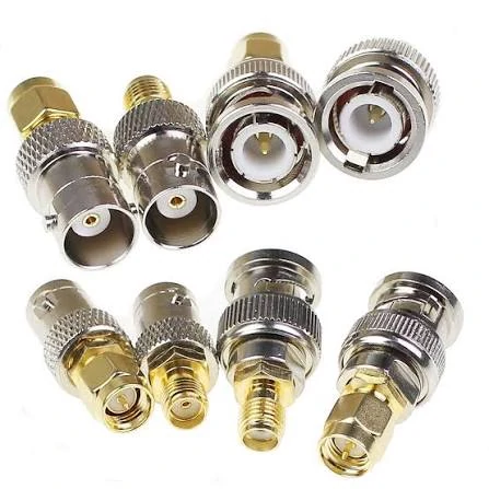
Comparison image showing BNC and SMA adapter structures for RF applications. Proper selection requires checking connector gender, impedance, frequency range, and application requirements before installation.
BNC and SMA connectors are often used in different parts of an RF system.
BNC is commonly found on laboratory instruments where fast connection is useful. Engineers working with oscilloscopes, signal generators, and older test equipment often encounter this interface.
SMA is more common on compact RF assemblies. Wireless modules, antenna systems, and many microwave components use SMA because the threaded coupling provides a more controlled mechanical connection.
When these interfaces need to work together, the adapter must match both sides.
A typical mistake happens when someone checks only the connector appearance.
A BNC connector may look correct in a product photo, but the actual requirement may be:
- BNC male to SMA female
- BNC female to SMA male
- BNC male to SMA male
- BNC female to SMA female
These are not interchangeable.
The correct combination depends on the ports already installed on the equipment.
A practical check before ordering:
| Confirm Before Purchase | Example |
| Equipment port | BNC female output |
| Cable connector | SMA male |
| Required adapter | Matching opposite interfaces |
| System impedance | 50Ω RF path |
| Working frequency | Based on application |
This step seems basic, but it prevents a common sourcing problem: receiving a part that is mechanically close but cannot be installed.
In production or laboratory purchasing, the adapter description should include both connector sides.
A request like:
“BNC adapter, 50 pcs”
leaves too many possibilities.
A clearer request would be:
“BNC female to SMA male adapter, 50Ω, for RF test connection.”
The additional information takes only a few seconds to provide but reduces unnecessary confirmation, replacement, and shipping time.
What Should Engineers Check Before Using a BNC to SMA Adapter?
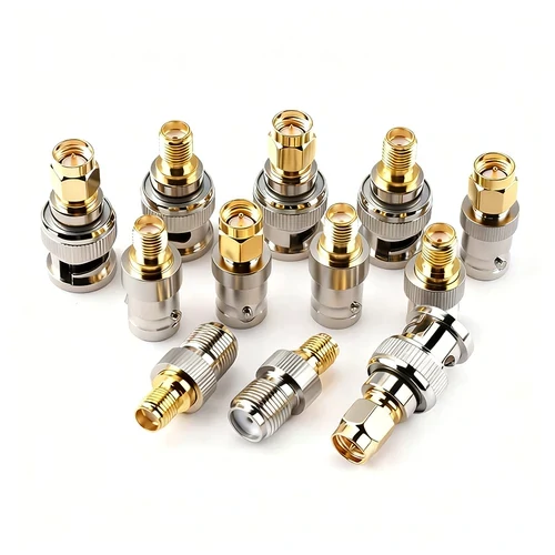
A collection of BNC to SMA adapters designed for RF systems requiring conversion between BNC and SMA connector interfaces. Different connector genders and structures are available for laboratory equipment, antenna systems, and RF test applications.
Mechanical connection is only the first check.
An adapter can physically connect two devices and still be unsuitable for the RF system.
The main points normally checked are:
Connector gender
The BNC and SMA sides must match the existing equipment.
Impedance
Most RF measurement systems use 50Ω components. However, BNC is also used in some 75Ω applications, especially outside typical RF measurement environments.
Frequency range
The adapter needs to support the operating frequency of the system. A part used for low-frequency measurement may not be the correct choice for a higher-frequency RF path.
Application environment
A temporary laboratory connection and a production test fixture may have different requirements.
For example, a prototype bench setup may only need a suitable interface transition. A production environment may also consider repeated mating, mechanical strength, and inspection consistency.
How Does Impedance Influence BNC to SMA Adapter Performance?
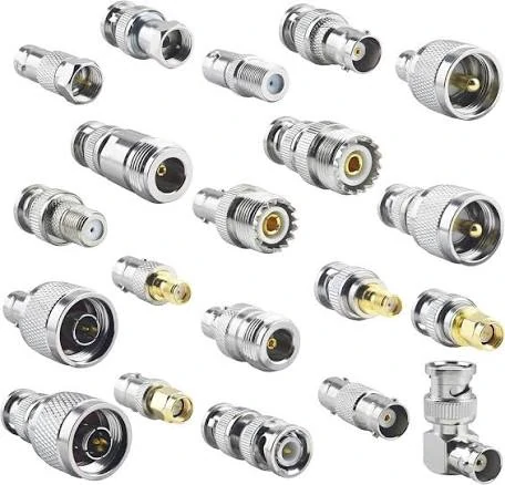
Multiple BNC to SMA adapter styles including male and female connector combinations. These RF adapters help connect test instruments, coaxial cables, and wireless modules while maintaining proper mechanical compatibility.
Once the interface and gender are confirmed, impedance becomes the next checkpoint. It is not a decorative line in the specification. It affects whether the adapter can sit in the RF path without creating extra trouble.
In most RF work, 50 ohms is the default environment. Test instruments, wireless modules, antenna feeds, and many coaxial assemblies are built around that standard. The problem is that BNC is not limited to one world. It appears in RF systems, but it also appears in video-related applications where 75 ohms is common. The connector family is familiar, the coupling style is familiar, and that is exactly why mistakes happen. The part looks acceptable at a glance, so the electrical side gets checked too late.
A BNC to SMA adapter should be treated like a path element, not a simple coupler. It sits between two interfaces and becomes part of the transmission line. If the rest of the setup is 50 ohms but one adapter is not aligned with that requirement, the bench may still power up and the cable may still mate correctly. The mismatch does not need to announce itself immediately. Sometimes it shows up as a small measurement drift. Sometimes the VNA trace becomes less clean than expected. Sometimes two benches that should agree no longer agree.
That kind of problem wastes time because the failure is not obvious. The user starts by checking the DUT, then the cable, then the instrument setting, while the adapter is still being treated as a harmless accessory.
A safer approach is to verify the impedance before ordering, not after testing.
The purchase note should not stop at “BNC to SMA adapter.” It should say what kind of system the part is entering. If the project is for RF measurement, that 50-ohm requirement belongs in the description. If the team is reusing older BNC cables or borrowing stock from another department, that should be checked too. Mixed inventory causes more trouble than many buyers expect.
One practical rule helps here: if the adapter is going into a measurement chain, assume nothing from appearance alone. Confirm the impedance on paper.
| Item to confirm | What should be written down |
| BNC side | Male or female |
| SMA side | Male or female |
| System impedance | 50Ω for most RF test paths |
| Intended use | Lab test, RF module check, antenna work, fixture use |
| Operating band | Maximum working frequency |
This table is simple on purpose. In purchasing, missing basic fields causes more delay than lack of advanced theory.
There is another point that matters in real work. Some engineers judge the adapter by whether the connection “works.” In low-frequency or non-critical use, that shortcut may slip by. In RF measurement, “works” is too loose a standard. A connection that passes continuity may still disturb matching enough to influence the result. That is not a dramatic failure. It is worse than that. It is a quiet one.
What Changes When the Frequency Goes Up?
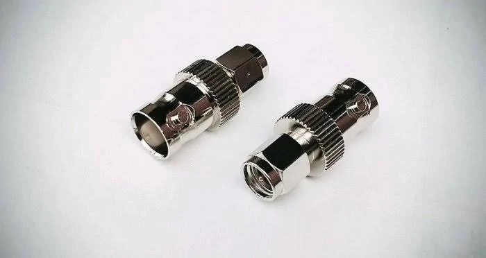
A BNC male to SMA female RF adapter used for connecting equipment with different coaxial connector interfaces. Suitable for RF testing, communication devices, and signal measurement applications requiring reliable connections.
Frequency changes the consequences of small details.
At modest operating ranges, an adapter may seem forgiving. The setup behaves reasonably well, the reading looks stable, and nobody questions the transition. As the frequency moves upward, the same relaxed attitude becomes risky. Small differences in construction begin to matter more than they did on a lower-band bench.
The contact structure matters. Alignment matters. So do dielectric consistency, machining quality, plating condition, and general dimensional control. None of this is surprising to RF engineers, but it is often lost when procurement focuses only on connector names.
Two adapters can share the same visible interface combination and still not belong in the same application. One may be adequate for basic signal routing. Another may be the safer choice for repeatable measurement. The catalog line item does not tell the whole story unless the frequency range is attached to it.
A useful way to think about this is margin.
If the system operates close to the upper limit of the adapter, there is less room for comfort. If the rating sits well above the operating band, the selection is usually easier to justify. This is not a substitute for measurement, but it is a practical selection habit.
A simple internal rule can help buyers and engineers speak the same language:
Frequency Margin Ratio = Adapter Rated Frequency ÷ Highest Operating Frequency
If a setup works at 3 GHz and the adapter is rated to 6 GHz, the margin ratio is 2. That does not guarantee perfect behavior, but it is a healthier starting point than using a part rated only slightly above the operating band.
The ratio can be read in a practical way:
- below 1.0: unsuitable
- around 1.2: only basic margin
- around 1.5: more comfortable for normal RF use
- around 2.0 or higher: better for measurement-sensitive work
That guideline is not a standard. It is an internal screening tool. The point is to prevent the common habit of choosing parts too close to the edge just because the connector combination matches.
Another issue shows up in adapter stacks. A single adapter may be acceptable. Several transitions in one path are another matter. Once the chain becomes instrument → cable → adapter → cable → second adapter → DUT, the path is no longer simple. Loss, mismatch, and mechanical variation accumulate quietly. Engineers know this. Buyers do not always see it from the BOM. Part 2 of a selection review should therefore include not only the adapter itself, but also how many interfaces the complete path contains.
That is where bench reality starts to matter more than catalog logic.
A prototype setup may tolerate extra transitions because the goal is fast verification. A production test setup usually deserves tighter control. Repeated mating cycles, operator handling, fixture stress, and cable routing all make the small RF parts matter more over time.
What Should Be Checked Before the Adapter Is Released for Use?
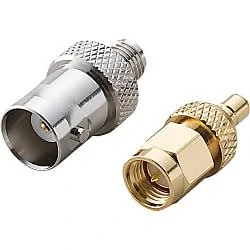
BNC to SMA coaxial adapters provide a practical solution for converting between bayonet-style BNC interfaces and threaded SMA interfaces. They are commonly used in RF laboratories, antennas, and communication equipment.
The first check is mechanical. The BNC locking action should feel correct. The SMA thread should engage cleanly, without looseness or damage. That is basic, but still worth stating, because poor mating condition is sometimes blamed on “RF performance” when the real issue is mechanical fit.
After that comes electrical confirmation. Continuity is the minimum check, not the final one. It proves that the path is closed. It does not prove that the path is suitable.
If the adapter is going into regular RF work, especially anything tied to measurement or acceptance testing, the better checks are VSWR, return loss, and insertion loss. Not every sample order needs a full lab report. Not every production order needs exhaustive data. But the farther the part moves from casual use toward controlled measurement, the less useful a continuity-only mindset becomes.
Inspection planning should match the application.
For a development bench, a basic incoming check may be enough. Engineers are changing cables, reworking modules, and testing quickly. The environment is flexible.
For a production fixture, expectations are different. The same adapter may be inserted and removed many times. Operators may tighten it differently. Cables may pull sideways. A part that looks fine at receiving may behave differently after repeated use. That is why production buyers usually need more than a connector name. They need a part definition, an application note, and some inspection expectation.
It is also worth recording what the adapter is not supposed to do. It is not there to rescue a poor cable choice. It is not there to compensate for an overloaded path with too many transitions. It is not there to make 50-ohm and 75-ohm sections behave like the same system. Its job is narrower than many BOMs suggest: provide the correct interface transition without adding unnecessary RF penalty.
That sounds simple. In practice, it is where many small measurement problems begin.
What Details Should Be Prepared Before Ordering a BNC to SMA Adapter?
In many RF projects, the adapter itself is not the difficult part. The difficult part is describing the requirement clearly.
A product name such as “BNC to SMA adapter” only defines the connector families. It does not tell the supplier which version is required.
The first confirmation usually comes from the equipment side.
Engineers need to check:
- the BNC port type
- the SMA port type
- male or female connection
- impedance requirement
- working frequency
- installation environment
This information is normally enough for standard adapter selection.
For a custom project, more details may be involved. The supplier may need to know whether the adapter will be installed in a test fixture, used on a cable assembly, or mounted inside equipment.
The same connector combination can have different requirements depending on the working condition.
A laboratory user may mainly care about measurement stability.
A production engineer may care more about repeated mating and batch consistency.
A purchasing department may focus on stable supply and clear part identification.
These details should be included before quotation whenever possible.
A practical specification example:
| Specification Field | Example |
| Adapter structure | BNC to SMA |
| BNC interface | Female |
| SMA interface | Male |
| Impedance | 50Ω |
| Application | RF test equipment |
| Quantity | Sample / Production |
This type of information reduces unnecessary communication after the order starts.
Why Do BOM Details Matter for RF Adapter Purchasing?
RF components are often small, but the information attached to them should not be small.
A short BOM description may create different interpretations between engineering and purchasing.
For example:
BNC-SMA adapter
This could refer to several products:
- BNC male to SMA female
- BNC female to SMA male
- Different impedance versions
- Different frequency ranges
- Different mechanical structures
The part number alone may solve this problem inside one company, but during supplier communication, a full description is still useful.
A clearer BOM entry might include:
50Ω BNC female to SMA male adapter for RF test connection
This description gives the supplier more useful information immediately.
For larger projects, companies often add additional fields:
| BOM Item | Suggested Information |
| Connector combination | Both sides specified |
| Electrical requirement | Impedance and frequency |
| Mechanical requirement | Thread, mounting, size |
| Application | Testing or equipment integration |
| Inspection | Required verification method |
This approach is especially useful when different departments handle purchasing, receiving, and assembly.
A purchasing employee may not know the RF application details. A complete BOM allows the supplier and production team to work from the same information.
How Should BNC to SMA Adapters Be Checked Before Production Use?
Incoming inspection does not need to be identical for every project.
The inspection level should match the role of the adapter.
For a development project, the basic checks may include:
- correct connector type
- correct quantity
- visible condition
- mechanical mating
For a production environment, the inspection requirement is usually more detailed.
The adapter may be connected and disconnected many times during daily operation. The cable may be moved. Operators may use different tightening force.
It does not replace RF measurement.
For applications involving sensitive measurement, additional testing such as VSWR or insertion loss checking may be required.
What Problems Usually Appear After Installation?
Some examples:
A BNC adapter is selected from general stock without checking impedance.
The connector fits, but the measurement result changes.
A correct adapter is selected, but several additional adapters are added to the RF path.
The system becomes harder to control.
A prototype adapter is used in a production fixture.
These situations show why the adapter should be considered together with the complete connection.
The cable, equipment, environment, and operating frequency all affect the final result.
FAQ
Is BNC to SMA the same as SMA to BNC?
The connector families are the same, but the direction and gender combination may be different.
The correct choice depends on which connector is installed on each side of the equipment.
Why does my adapter fit but the RF test result change?
Mechanical connection does not always represent RF compatibility.
Possible factors include impedance mismatch, frequency limitation, cable differences, or additional transitions in the setup.
Do I need a 50Ω BNC to SMA adapter?
For most RF measurement systems, yes.
However, the impedance should always be confirmed from the equipment specification because BNC products are also used in some 75Ω systems.
Can a BNC to SMA adapter be used outdoors?
It depends on the product construction.
Standard adapters are mainly used in controlled environments.
Can suppliers provide customized BNC to SMA adapters?
Yes.
Customization may involve connector combinations, dimensions, materials, plating, and application requirements.
The supplier normally needs the interface information and operating conditions before confirming the design.
Practical Notes Before Selecting a BNC to SMA Adapter
A BNC to SMA adapter is often purchased as a small accessory, but it can influence the entire RF connection.
The most useful information to provide before ordering is not only the connector name. The supplier should understand where the adapter will be installed, what equipment it connects, and what electrical conditions it needs to support.
For standard applications, clear interface information may be enough.
For measurement systems or production equipment, impedance, frequency range, inspection requirements, and application details should be included from the beginning.