
A customer sends a drawing with only one note: “SMA female connector required.”
For a supplier, that description is usually not enough.
The interface name tells only part of the story. The final connector may be installed on a PCB, fixed to a metal enclosure, connected to an antenna cable, or used as a test port. Each situation requires a different mechanical design.
This is where many RF projects run into trouble. The sample fits the port, the thread can be tightened, and the assembly looks correct. After integration, problems appear during RF testing because the connector choice did not consider the cable, mounting structure, or operating frequency.
An sma female connector is commonly used as the equipment-side RF interface. It normally connects with an SMA male connector through a threaded coupling structure. However, the connector itself is only one part of the RF path.
How Does an SMA Female Connector Fit Into an RF System?
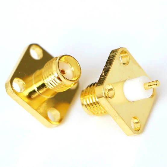
This SMA female connector features a compact threaded interface and panel mounting design, suitable for RF equipment, communication devices, antenna systems, and test applications requiring stable 50 ohm connections.
Some are soldered directly onto a PCB. Others are mounted through an enclosure panel and connected internally with an RF cable assembly.
The difference between these applications is easy to overlook.
A PCB-mounted connector mainly depends on board layout, solder quality, and mechanical support. When the connector, cable, and connected equipment do not maintain the same impedance, unwanted reflection can appear. During testing, this may show as higher VSWR or unexpected insertion loss.
A connector that works in a short laboratory setup may not behave the same after being installed into a finished product.
Check the Interface Before Selecting the Connector
One common sourcing issue is that the term “SMA” is used too broadly.
A buyer may request an SMA cable, while the engineering drawing actually requires a specific combination:
- SMA female equipment port
- SMA male cable end
- 50 ohm coaxial cable
- Required operating frequency
- Defined cable length
Without this information, different suppliers may understand the request differently.
The table below shows the basic relationship between common SMA interfaces.
The center contact is the easiest way to identify standard SMA gender. Looking only at the outer threaded body can cause mistakes because SMA and RP-SMA products may appear similar from the outside.
This issue appears frequently in antenna applications. WiFi equipment, for example, may use RP-SMA connectors instead of standard SMA. A cable that looks correct may still be unable to mate with the equipment port.
Choose the Mounting Style According to the Installation
The front interface may be the same, but the mounting structure changes depending on where the connector will be installed.
| Mounting Style | Common Application | Main Point to Confirm |
| PCB Mount | RF module, wireless board | PCB footprint and solder method |
| Bulkhead Mount | Equipment enclosure | Panel thickness and fixing hardware |
| Panel Mount | External RF port | Hole size and mechanical strength |
| Cable Mount | Flexible RF connection | Cable diameter and termination |
For a production project, the mounting style should be confirmed before samples are made.
For example, an engineer replacing a PCB SMA female connector with a bulkhead version may find that the electrical interface is correct but the mechanical structure no longer fits. The opposite situation also happens: a compact PCB connector is selected for a panel application where stronger fixing is required.
These details are usually easy to confirm during the RFQ stage but expensive to correct after production starts.
Match SMA Female Connectors With the RF Cable
The connector and cable should be treated as one assembly.
An SMA connector designed for RG316 is not automatically suitable for a larger coaxial cable. The rear body, ferrule size, and termination process are normally matched to a specific cable diameter.
Common cable options used with SMA assemblies include:
- RG316 for flexible compact connections
- RG178 for small diameter routing
- Mini coax for compact wireless products
- Low loss RF cable for longer transmission paths
Cable length also affects the final result. A short jumper used in a test environment may show acceptable loss, while a longer cable installed inside equipment may require a different cable type.
For this reason, a complete specification is usually more useful than a connector name alone.
A practical RF request should include:
- Connector type and gender
- Cable type
- Cable length
- Impedance
- Frequency requirement
- Termination method
- Testing requirement
Practical Note for RF Buyers
Before approving an SMA female connector for production, check both mechanical and electrical requirements.
Mechanical inspection can confirm:
- Correct interface
- Thread condition
- Mounting size
- Contact appearance
RF verification may include:
- Continuity test
- VSWR measurement
- Return loss check
- Insertion loss test
Continuity only confirms that the circuit is connected. It does not prove that the RF path will perform correctly at the target frequency.
A suitable SMA solution comes from matching the connector, cable, mounting method, and application together.
How Should You Select the Right SMA Female Mounting Style?
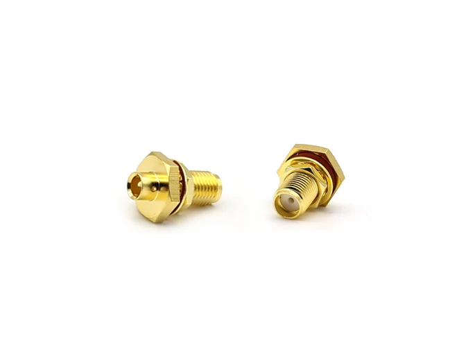
The SMA female bulkhead connector provides a secure mounting solution for RF enclosures, communication equipment, and antenna interfaces. It supports reliable signal transmission with a standard threaded SMA connection.
A connector can have the correct SMA interface and still be the wrong part for the equipment.
This happens when the mounting method is ignored.
During early design, engineers often focus on the RF interface first. The connector mates correctly, the frequency rating looks acceptable, and the footprint appears close. The issue comes later when the mechanical team checks the enclosure, the PCB layout changes, or the cable inside the equipment has nowhere to bend.
For an sma female connector, the mounting style should be selected according to where the connector will physically work.
Use PCB Mount SMA Female Connectors for Board-Level RF Connections
This reduces additional cable connections and keeps the RF path shorter.
However, the connector selection should not stop at the footprint.
Before placing the order, engineers normally need to confirm:
- PCB thickness
- Ground pad design
- Mounting hole position
- Center pin height
- Soldering method
- Assembly process
A connector that fits the drawing may still create problems if the center contact height does not match the PCB layout.
In microwave or higher-frequency designs, the transition area between the connector and PCB trace is especially important. Poor grounding around the connector area can affect impedance consistency and increase measurement variation.
This is why RF engineers usually check the connector together with the PCB design rather than treating it as a separate component.
Select an SMA Bulkhead Connector for Fixed Equipment Panels
When an RF port needs to be accessible from outside an enclosure, an sma bulkhead connector is often considered.
This type of connector is designed for panel installation. The threaded body passes through the equipment wall and is fixed with a nut or mounting hardware.
Typical applications include:
- RF test equipment
- Communication devices
- Antenna control boxes
- Industrial wireless systems
- Laboratory fixtures
The mechanical details are important here.
A buyer should confirm:
| Item | Why It Matters |
| Panel thickness | Determines whether the connector can be fixed correctly |
| Mounting hole size | Prevents installation mismatch |
| Cable exit direction | Affects internal routing space |
| Sealing requirement | Important for outdoor or industrial equipment |
| Connector length | Avoids interference inside the enclosure |
A common mistake is ordering based only on the front SMA interface.
When Does a Cable Mount SMA Female Connector Make More Sense?
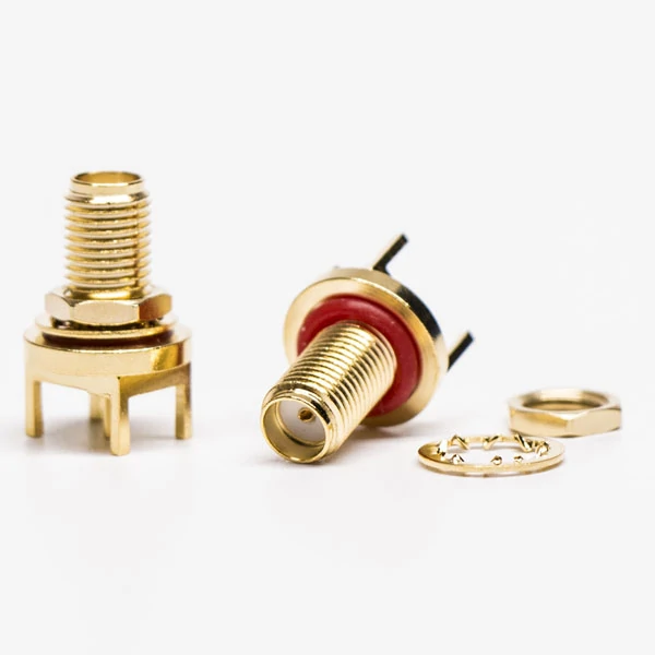
This SMA female adapter connector is used for RF testing systems, communication equipment, and cable connections. The precision-machined interface helps maintain stable impedance performance and signal integrity.
Some systems need flexibility rather than a fixed board or panel connection.
In these cases, a cable-mounted solution may be more suitable.
An SMA cable assembly usually combines the connector and coaxial cable as one tested unit. This approach is common in:
- RF test cables
- Internal equipment wiring
- Antenna extensions
- Communication modules
The benefit is not only convenience. A complete cable assembly can provide better consistency because the connector termination and cable selection are controlled together.
For example, an SMA cable assembly using RG316 cable requires a connector body designed for that cable diameter. The crimp sleeve, center pin, and rear body all need to match.
A sample assembled manually may work, while hundreds of production pieces may show different results if the connector and cable combination is not controlled.
How Do SMA Female Connectors Match RF Cables?
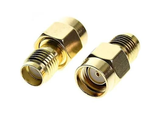
The SMA female flange connector uses a fixed mounting structure with screw holes, making it suitable for RF modules, test fixtures, and industrial communication equipment requiring mechanical stability.
The connector is only one part of the transmission path.
The cable connected behind the SMA interface often determines the practical performance of the assembly.
A short cable for laboratory testing may prioritize flexibility. A longer cable inside communication equipment may require lower attenuation. A microwave test cable may need tighter control of VSWR and phase stability.
Common cable choices include:
| Cable Type | Typical Feature | Common Application |
| RG316 | Flexible, small diameter | Internal wiring, short RF connection |
| RG178 | Smaller size | Compact wireless equipment |
| Mini coax | Space-saving design | IoT and embedded devices |
| Low loss RF cable | Reduced attenuation | Longer RF transmission paths |
The phrase “SMA cable” is often too general for purchasing.
A better specification describes the complete assembly:
Example:
SMA female to SMA male cable assembly, 50 ohm, RG316 cable, 500 mm length, operating frequency DC–6 GHz, tested for continuity and VSWR.
This gives the supplier enough information to select the correct connector body and cable combination.
Why Cable Length Changes SMA Connector Selection
A common laboratory mistake is approving a cable based on a short sample.
The sample works because the cable is short, straight, and installed in an open environment.
The production version may be different.
A longer cable routed around corners inside a device can introduce additional loss. Tight bending can also affect the cable structure and change RF characteristics.
For this reason, RF cable selection should consider:
- Operating frequency
- Cable length
- Bend radius
- Installation space
- Expected mating cycles
A high-frequency connector does not automatically solve cable limitations.
For example, selecting a microwave connector with a very high frequency rating does not improve the performance of a cable that has excessive loss at the working frequency.
The connector, cable, and application need to be evaluated together.
Practical Selection Table for SMA Female Applications
The following matrix can help during early product selection:
| Application | Recommended Mounting Style | Main Check |
| Wireless PCB module | PCB mount SMA female | Footprint and RF layout |
| External equipment port | Bulkhead SMA female | Panel size and fixing |
| Test fixture | Panel or bulkhead type | Mating cycles and VSWR |
| Internal RF connection | SMA cable assembly | Cable type and routing |
| Antenna extension | Cable assembly | SMA/RP-SMA confirmation |
This type of information is useful during RF procurement because it connects the connector name with the actual working environment.
A good RF specification does not only answer “which connector?”
It also answers:
- Where will it be installed?
- What cable will be connected?
- What frequency will it handle?
- How will it be tested?
That information prevents many replacement and rework issues before production begins.
Verify the SMA Female Connector Before It Enters Production
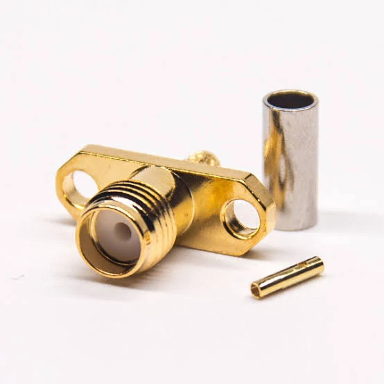
This SMA female four hole flange connector provides mechanical reinforcement and reliable RF performance for microwave modules, communication systems, and precision testing equipment.
The first sample is usually the easiest one to pass.
It is normally assembled carefully, tested in a clean environment, and handled by the engineer who knows the design. The situation can change after the project moves into regular production.
A cable length may change.
The routing inside the enclosure may become tighter.
A different operator may assemble the connector.
Small differences that are invisible during visual inspection can appear during RF testing.
For an sma female connector, production approval should not stop at checking whether the connector can be installed. The complete RF connection needs to be considered.
Frequency Data Is Only One Part of the RF Decision
Connector datasheets usually provide frequency information, but the number should be viewed together with the application.
A connector marked for a higher frequency range does not automatically make the whole assembly suitable for that frequency.
The signal path also includes:
- Coaxial cable
- Cable length
- Connector termination
- Adapter connection
- PCB transition
In some projects, the cable becomes the limiting factor before the connector reaches its own specification.
A short RG316 cable may work well for an internal connection. A longer cable using the same connector may require a different solution because attenuation increases with length.
This is why RF engineers usually check the entire assembly rather than selecting a connector only from a frequency number.
The Cable Behind the Connector Often Decides the Result
During purchasing, “SMA cable” is one of the least specific descriptions.
It tells the supplier the interface family, but many details are still missing.
A complete SMA cable assembly normally needs information such as:
- SMA gender
- Cable type
- Cable length
- Impedance
- Operating frequency
- Termination method
For example, an SMA female to SMA male cable using RG316 is a different product from an SMA assembly using a larger low loss cable.
The front connector may look identical, but the rear structure is different.
The connector body, ferrule, and termination process must match the cable diameter. If they do not, problems may appear as:
- Weak cable retention
- Poor shielding contact
- Assembly inconsistency
- Unstable RF measurement
This is especially important for production orders. A sample made by an experienced technician may pass, while repeated assembly creates variation.
RF Testing Shows Problems That Appearance Cannot Find
A connector can look perfect and still fail an RF measurement.
Visual inspection is useful for checking:
- Housing damage
- Thread condition
- Contact position
- Mounting dimensions
However, these checks cannot confirm RF behavior.
For an RF connector system, engineers may use:
| Test | Purpose |
| Continuity | Confirm electrical connection |
| VSWR | Check impedance matching |
| Return Loss | Evaluate reflected energy |
| Insertion Loss | Measure signal loss |
A continuity test is often the first step, but it is not the final answer.
A connection may show electrical continuity while still having poor RF characteristics at higher frequencies.
This difference is one reason why professional RF suppliers separate basic inspection from RF performance testing.
When a Precision Microwave Connector Makes Sense
Not every project needs a precision connector.
For a general communication device, a standard SMA solution may already meet the requirement.
The situation changes for measurement applications.
A microwave connector is usually considered when the system needs tighter control, such as:
- Calibration equipment
- RF test fixtures
- Laboratory measurement systems
- High-frequency evaluation equipment
In these applications, repeatability becomes a key factor.
The connector may be connected and disconnected hundreds of times. Mechanical wear, contact condition, and installation consistency can influence measurement results.
A more expensive connector is not always the answer. The complete test setup still depends on cable quality, calibration method, and handling conditions.
Information Required for SMA Female Connector Approval
A clear specification makes supplier communication much easier.
A practical request usually includes:
| Item | Example |
| Interface | SMA Female |
| Impedance | 50 ohm |
| Mounting | PCB / Bulkhead / Panel |
| Cable | RG316 / RG178 / Low Loss Cable |
| Frequency | Application requirement |
| Assembly | Crimp or solder |
| Inspection | VSWR or other RF test |
This information helps avoid a common situation: the supplier provides a connector that matches the drawing, but the final assembly does not match the actual working condition.
The missing information is often the real problem.
FAQ
Why can an SMA connector pass continuity but fail RF testing?
Because continuity only checks whether the electrical path is connected. It does not show impedance matching, reflection, or transmission loss at the working frequency.
I only need an SMA cable. Why does the supplier ask for more information?
“SMA cable” describes only the connector family, not the complete assembly. The supplier still needs to know the connector gender, cable type, length, impedance, frequency range, and termination method. For example, an SMA cable assembly using RG316 is different from one using a low loss RF cable, even if the front interface looks the same.
Can I replace an SMA female connector with an RP-SMA connector if the thread size is the same?
No. The external appearance can be misleading because the main difference is inside the connector. Standard SMA and RP-SMA use different center contact arrangements. This issue is common in antenna and wireless equipment projects, so the interface should be confirmed from the contact structure or drawing before ordering.
What information does a supplier need for an SMA cable quote?
“SMA cable” alone does not define the product. The supplier normally needs the connector side, cable type, cable length, impedance, frequency range, and termination method. These details decide the actual SMA cable assembly structure.