
A cable assembly can pass continuity and still be the wrong RF part.
This happens more often than many buyers expect. The connector mates correctly, the cable looks similar to the previous order, and the first sample works on the bench. Problems usually appear later — after the cable is installed into a tighter enclosure, routed near other components, or tested at the upper edge of the operating frequency.
Two SMA connectors may look almost identical in a product photo. The difference may be hidden inside the interface structure, cable termination method, or frequency capability.
For RF engineers and procurement teams, selecting an SMA male connector is not only about matching threads. The connector must match the cable, impedance, frequency range, installation method, and final application.
How Does an SMA Male Connector Maintain Reliable RF Connections?
An SMA male connector is commonly used as a compact RF interface between cables, modules, antennas, and test equipment. The front interface is only one part of the complete RF path. The internal geometry, contact alignment, dielectric structure, and connection with the cable all influence the final signal behavior.
In an RF system, the connector has several jobs:
- Provide mechanical connection between two components
- Maintain electrical continuity through the signal path
- Keep a controlled 50Ω impedance environment
- Support stable high-frequency transmission
A connector that only fits mechanically may still create problems electrically.
For example, a cable assembly used for a VNA test setup may require better repeatability than a general wireless module connection. The same SMA interface may appear suitable, but the internal manufacturing tolerance, termination quality, and inspection requirement can be different.
Explain the role of SMA male connectors in RF signal paths
The SMA male connector normally contains a center pin that mates with the female socket contact. The threaded coupling mechanism provides a secure connection compared with push-pull interfaces.
Common applications include:
- RF modules
- Wireless communication equipment
- Laboratory test instruments
- Antenna systems
- Microwave assemblies
However, the connector should always be evaluated together with the cable assembly. A high-frequency connector cannot compensate for a cable that has excessive loss, poor shielding, or an unsuitable bend radius.
A typical procurement mistake is specifying only:
“SMA cable”
This description is incomplete.
A more useful specification should include:
| BOM Item | Recommended Information |
| Interface | SMA male |
| Impedance | 50Ω |
| Cable type | RG316 / RG178 / low-loss coax |
| Length | Required cable length |
| Frequency | Target operating frequency |
| Termination | Crimp, solder, or other method |
| Test requirement | VSWR / insertion loss if required |
The cable behind the connector often determines the practical performance limit.
Identify why SMA connectors are widely used in RF designs
SMA remains popular because it provides a balance between size, frequency capability, and mechanical stability.
Compared with larger connectors such as N Type, SMA provides a smaller footprint. Compared with quick-lock interfaces such as BNC, SMA provides stronger mechanical retention for many RF applications.
The practical selection rule is simple:
The connector interface should match the system requirement, not only the available installation space.
How Do SMA Male and Female Connectors Work Together?
Many RF connection problems are caused by confusing connector gender.
The SMA family uses different contact structures for male and female versions. Although the external thread appearance may look similar, the electrical interface is different.
Understand the contact difference between male and female versions
The basic difference is the center contact.
| Connector Type | Contact Structure | Typical Position |
| SMA Male | Center pin | Cable end or equipment connector |
| SMA Female | Socket contact | Device port or cable interface |
An SMA male connector normally provides the protruding center pin, while the SMA female connector receives that pin through a socket contact.
Before ordering or assembling an RF cable, confirm:
- Connector gender
- Device port type
- Cable end interface
- Thread compatibility
- Impedance requirement
A connector mismatch may appear obvious during assembly, but RP-SMA versions create a more common sourcing problem because the outside dimensions can look similar.
Avoid confusing SMA with reverse polarity SMA
RP-SMA (Reverse Polarity SMA) is widely used in some wireless products, especially WiFi equipment.
The external appearance can be misleading because the thread structure remains similar. The difference is the center contact arrangement.
| Connector Type | Contact | Common Application |
| SMA Male | Pin | Standard SMA cable connection |
| SMA Female | Socket | Standard equipment port |
| RP-SMA Male | Socket | WiFi equipment |
| RP-SMA Female | Pin | Reverse polarity systems |
SMA and RP-SMA should not be treated as interchangeable.
A cable that mechanically connects may still create an incorrect electrical interface. This is why connector polarity should be clearly listed in the BOM before purchasing.
How Should SMA Male Connectors Be Matched With RF Cables?
A common problem appears when a buyer receives an RF cable assembly that looks correct but performs differently from the previous batch.
The connector is still SMA. The cable length is still the same. The product drawing has not changed.
But the test result moves.
The reason is usually not the front interface. The problem is often hidden in the cable selection or termination details behind the connector.
An SMA male connector is only one section of the RF path. The cable type, center conductor size, dielectric material, shielding structure, and assembly process all affect the final result.
For production purchasing, the connector and cable should be treated as one assembly rather than two separate parts.
Match the connector body with the cable construction
Different coaxial cables require different SMA connector designs.
A small flexible cable such as RG316 has a different outer diameter and conductor structure compared with RG58 or RG142. The SMA front interface may be identical, but the rear termination section is not interchangeable.
This is a detail that often causes problems during replacement sourcing.
Without these details, two suppliers can provide products that look similar but are not equivalent.
| Cable Application | Common Cable Choice | Selection Concern |
| Compact internal connection | RG316 / RG178 | Flexibility and space |
| Wireless module connection | 1.13mm coax | Small diameter matching |
| Longer RF path | Low loss RF cable | Attenuation control |
| Larger equipment wiring | RG58 / RG142 | Connector rear size |
The cable can become the limiting factor before the connector reaches its rated frequency.
A high-frequency SMA connector connected with an unsuitable cable does not create a high-frequency assembly.
Check impedance before ordering SMA cable assemblies
Most SMA applications use a 50 ohm RF system.
This specification should remain consistent across:
- Connector
- Cable
- Adapter
- Equipment port
A physical connection does not always mean an RF-compatible connection.
A 50 ohm SMA connector attached to an incorrect cable type may still pass a continuity check. The problem appears later during RF measurement.
Typical symptoms include:
- Higher VSWR
- Increased return loss
- Signal instability
- Different measurement results between batches
For this reason, procurement documents should avoid descriptions like:
“SMA cable”
A better BOM description contains the actual RF requirements.
Example:
| Specification Item | Example Requirement |
| Connector | SMA male |
| Cable | RG316 coaxial cable |
| Impedance | 50Ω |
| Length | 300 mm |
| Frequency | Application dependent |
| Termination | Crimp type |
| Inspection | VSWR check if required |
This type of information reduces unnecessary substitutions during purchasing.
When should you choose an SMA cable assembly instead of separate parts?
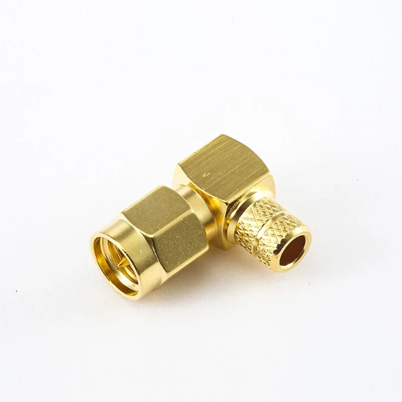
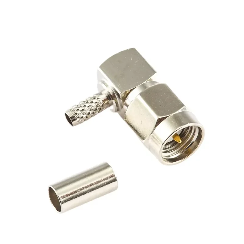
This image shows a right angle SMA male connector suitable for space-limited RF applications. The angled design helps reduce cable bending stress while maintaining reliable 50 ohm RF connections for antennas, modules, and communication equipment.
For production equipment, finished SMA cable assemblies are usually easier to control.
A complete assembly allows the supplier to control:
- Cable stripping length
- Contact position
- Crimp force
- Solder temperature
- Final inspection
This matters when the order quantity increases.
A single prototype can hide variation.
A batch of several hundred pieces will reveal it.
SMA Cable Assembly Specification Sheet
Before sending an RF cable inquiry, provide these fields:
| Field | Information Required |
| Connector A | SMA male/female |
| Connector B | SMA or other interface |
| Cable model | RG316, RG178, low loss coax, etc. |
| Impedance | 50Ω |
| Cable length | Actual installed length |
| Operating frequency | Working band |
| Installation condition | Indoor/outdoor/bending requirement |
| Test requirement | VSWR, insertion loss, continuity |
This specification format is closer to how RF suppliers evaluate a project.
How Do Mounting Styles Change SMA Connector Selection?
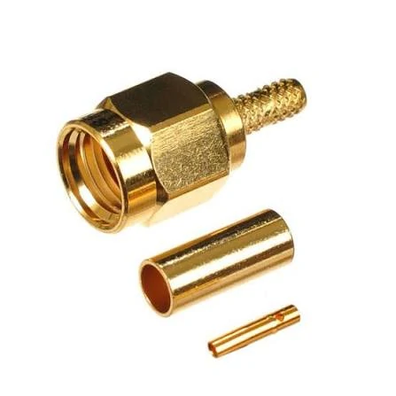
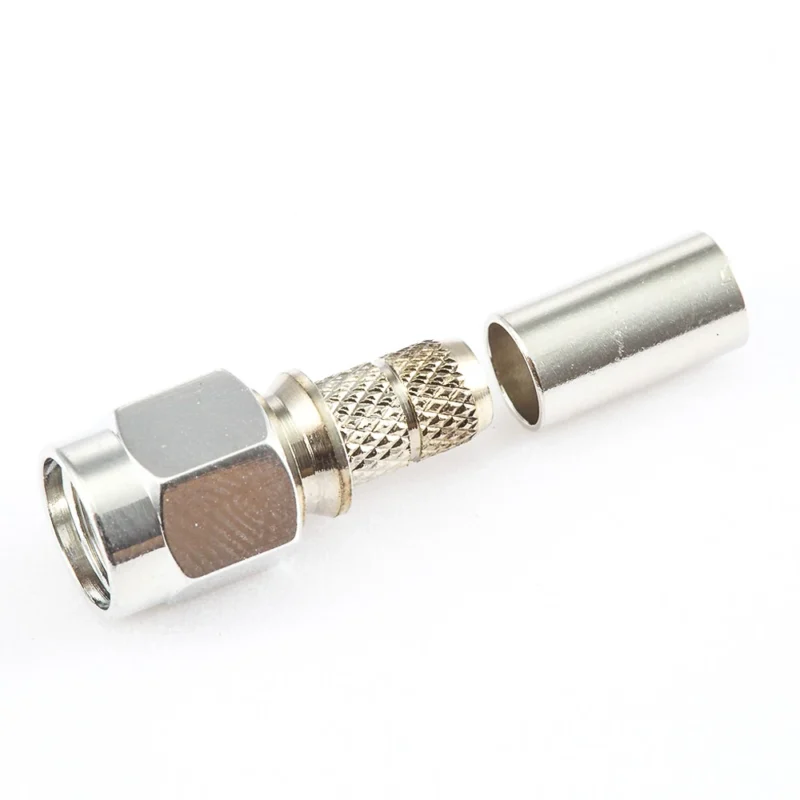
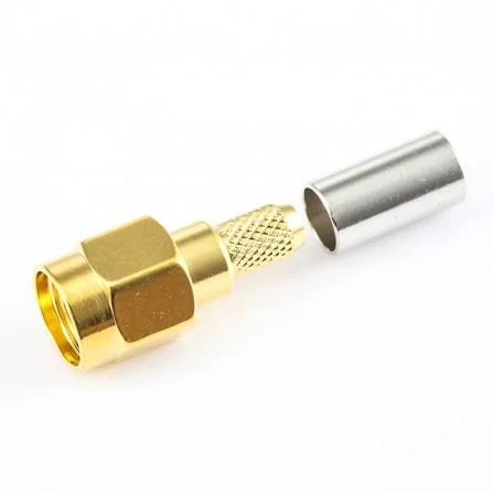
This image presents a cable mount SMA male connector used in RF cable assemblies. The rear termination section is designed for coaxial cable connection, supporting applications including antennas, wireless devices, and RF testing systems.
The same SMA male interface can appear in different mechanical forms.
A cable assembly inside a device, a panel connector on a test box, and a PCB connector on an RF module may all use SMA, but the installation requirements are different.
Selecting the wrong mounting method can create mechanical problems even when the RF interface is correct.
When does a cable mount SMA connector make sense?
Cable mount versions are mainly used when the RF connection needs flexibility.
Typical examples:
- Antenna cables
- RF module wiring
- Test leads
- Internal equipment connections
The rear section must match the cable.
A connector designed for one cable diameter cannot simply be installed on another cable by changing the stripping length.
During production, suppliers normally control:
- Strip dimensions
- Crimp tooling
- Center conductor position
- Pull force
These factors affect both mechanical reliability and RF consistency.
Why do engineers choose SMA bulkhead connectors?
A bulkhead SMA connector is used when the RF interface needs to pass through an equipment panel.
Common applications include:
- Test instruments
- Communication equipment
- Outdoor enclosures
- RF measurement fixtures
The selection is not only about the connector itself.
The installation drawing should confirm:
- Panel thickness
- Mounting hole size
- Fixing method
- Connector orientation
- Environmental requirements
A mismatch here can create assembly delays.
For example, a connector may be electrically correct but impossible to install because the panel opening or fixing method does not match the equipment design.
How should PCB SMA connectors be evaluated?
PCB mount SMA connectors are directly connected to the RF circuit.
In this case, the connector is part of the transmission path.
Engineers should review:
- PCB footprint
- Ground connection
- RF trace design
- Mechanical support
A good connector cannot compensate for a poor PCB transition.
At higher frequencies, the launch area between connector and PCB becomes part of the RF design.
SMA Mounting Selection Matrix
| Application Situation | Recommended Style | Main Check |
| Flexible cable connection | Cable mount | Cable compatibility |
| Equipment panel interface | Bulkhead | Mechanical installation |
| RF board connection | PCB mount | PCB layout |
| Limited installation space | Right angle | Cable routing |
How Does Frequency Range Affect SMA Male Connector Selection?
A higher frequency rating on a connector datasheet does not automatically mean better system performance.
The final RF result depends on the complete assembly.
A test cable using multiple adapters, a long coaxial cable, and several connection points may perform differently from a short cable used inside a module.
This is why engineers normally evaluate the whole RF path instead of looking at the connector specification alone.
Check frequency margin before selecting a connector
When selecting an SMA male connector, review:
- Operating frequency
- Connector frequency capability
- Cable attenuation
- VSWR requirement
- Number of RF connections
A useful engineering practice is keeping frequency margin.
For example:
- A general wireless product may use a standard SMA solution.
- A measurement cable operating near the upper frequency limit may require a more controlled connector design.
Why do high-frequency applications require more attention?
At microwave frequencies, small manufacturing differences become measurable.
Factors include:
- Center pin alignment
- Dielectric positioning
- Contact surface quality
- Machining tolerance
- Assembly repeatability
This explains why two SMA connectors from different production sources may have different test results even if the external dimensions appear identical.
For engineering purchasing, the question is not only:
“Can this connector reach the frequency?”
A better question is:
“Can this connector maintain stable performance in the complete assembly?”
Where Do SMA Male Connectors Appear in Wireless and Antenna Systems?
A damaged antenna cable does not always look damaged.
In some field repairs, the connector can still screw onto the equipment correctly, and the cable may have no visible marks. The problem appears only after the device is installed back into the system.
Signal range becomes shorter. The wireless link becomes unstable. A GPS module takes longer to lock.
The reason is often hidden in small details:
- SMA or RP-SMA interface
- Cable attenuation
- Cable routing
- Connector termination
- Actual operating frequency
For antenna systems, the SMA male connector is only the mechanical and electrical transition point. The cable and the equipment behind it are equally important.
Check the connector type before replacing WiFi antenna cables
WiFi products are a common source of SMA replacement mistakes.
A customer may send a photo and request:
“Need the same antenna cable.”
The connector looks familiar. The thread size appears correct.
However, the internal contact may be different.
Some wireless devices use standard SMA. Others use RP-SMA. These two interfaces are easy to confuse because the outside shape is similar.
Before replacing a wifi antenna cable, engineers usually confirm:
- Connector polarity
- Equipment model
- Frequency band
- Cable length
- Installation position
A wrong polarity cable may physically attach to the device but still fail electrically.
This is why experienced buyers usually provide a drawing, sample, or equipment information instead of relying only on product photos.
Why cable selection matters in GPS and embedded RF designs
GPS antenna cables are often installed in compact products.
The available space may be limited, so miniature coaxial cables are commonly selected.
A short cable inside a navigation device and a longer cable routed through equipment should not be evaluated the same way.
The difference comes from cable loss.
A longer RF path introduces more attenuation. At higher frequencies, this loss becomes easier to notice.
Engineers normally look at:
| Item | Why it affects selection |
| Cable length | Longer cable increases signal loss |
| Cable diameter | Influences attenuation and flexibility |
| Installation space | Determines routing options |
| Frequency range | Affects practical cable choice |
A smaller cable is not always the better choice. It may simplify installation, but the trade-off can be higher loss.
For embedded RF designs, the connector, cable, and antenna position need to be considered together.
How should coax antenna cables be selected for different environments?
The same SMA interface can be used in different equipment, but the cable behind it may be completely different.
A short internal connection inside an RF module has different requirements from an outdoor antenna cable.
Typical situations include:
| Application | Common Requirement |
| Internal wireless module | Small diameter and flexibility |
| Antenna extension | Lower loss and mechanical strength |
| RF test cable | Repeatability and measurement stability |
| Outdoor equipment | Environmental protection |
A coax antenna cable used outdoors may need stronger protection.
A cable used in a test laboratory may focus more on repeatability.
The connector type alone does not define the complete RF solution.
How Should SMA Assemblies Be Checked Before Production?
The sample may have been:
- Carefully assembled by an experienced technician
- Tested with a short cable length
- Installed in an open environment
The final product may have:
- Different cable routing
- Different assembly operators
- More bending stress
- Larger quantity variation
For RF products, the transition from sample to production deserves attention.
Start with mechanical inspection
A basic inspection can find many assembly problems.
Common checks include:
- Connector appearance
- Thread condition
- Center contact
- Cable jacket
- Crimp area
- Strain relief
A loose crimp or damaged cable may not immediately stop electrical continuity testing.
However, the problem can appear after vibration, repeated installation, or long-term use.
Continuity is only the first test
Continuity testing is useful during production inspection.
It confirms that the conductor path is connected.
It does not show whether the RF path is working correctly.
For applications with higher requirements, additional measurements may include:
| Test | Purpose |
| VSWR | Check impedance matching |
| Return Loss | Evaluate reflected signal |
| Insertion Loss | Measure transmission loss |
| VNA Sweep | Review frequency response |
A cable assembly can pass continuity and still have poor RF performance.
This difference becomes important in:
- Test equipment cables
- Microwave applications
- Long cable assemblies
- Precision RF measurement systems
SMA assembly inspection reference
A practical inspection record may include:
| Inspection Item | Record |
| Connector interface | SMA male confirmed |
| Polarity | Standard SMA / RP-SMA |
| Cable model | Confirmed |
| Cable length | Measured |
| Appearance | Passed |
| Continuity | Passed |
| VSWR | Tested if required |
| Final status | Accepted / Rejected |
This type of record is useful when a project moves from prototype into regular production.
What Information Should Be Provided When Purchasing SMA Male Connectors?
Many sourcing delays start with incomplete specifications.
A request such as:
“SMA male connector, 1000 pcs”
does not tell the supplier enough information.
FAQ
Can an SMA male connector work with any SMA-style antenna port?
Not always. Standard SMA and RP-SMA have different contact arrangements. The outside appearance can be misleading, so the equipment interface should be confirmed before ordering.
Why does a replacement SMA antenna cable sometimes perform differently?
Possible reasons include different cable loss, different cable length, incorrect polarity, or different assembly quality. A cable that looks similar may not have the same RF characteristics.
Does passing continuity mean an SMA cable assembly is qualified?
No. Continuity confirms electrical connection only. RF tests such as VSWR or insertion loss may still be required depending on the application.
What information should I provide when requesting an SMA male connector or cable assembly?
A supplier normally needs more than the connector name. Provide the SMA interface type, cable model, impedance, cable length, operating frequency, mounting style, termination method, and testing requirements. Clear specifications help avoid receiving a product that looks correct but does not match the RF application.
What details should I send when asking for an SMA male cable assembly quote?
A product name alone usually is not enough.
For example, “SMA cable” does not tell the supplier the cable type, length, frequency range, or termination method. A useful request normally includes the SMA interface, cable model, cable length, impedance, working frequency, and any test requirements. These details help the supplier evaluate whether the assembly matches the actual application.
