
A cable assembly can look correct on a drawing and still fail after it reaches production.
A common situation happens during RF sourcing. The connector interface is correct, the cable length matches the requirement, and the first sample passes a basic continuity check. Then the assembly is installed into the final device. The cable is bent tighter than expected, routed next to a power circuit, or tested at a higher frequency. Suddenly, the measured loss or VSWR is outside the acceptable range.
The problem is usually not the connector alone.
The RF cable itself has become part of the system design.
Many purchasing requests only include simple information:
“Need 50 ohm RF cable, SMA connector, 1 meter.”
For low-frequency applications, this may be enough to start a discussion. For higher frequency systems, it leaves several unanswered questions:
- What frequency range will the cable actually operate at?
- Is the cable required to be flexible or low loss?
- How many connectors and adapters are included in the RF path?
- Does the installation require shielding against interference?
- Is the cable being used for antenna connection, testing, or internal wiring?
A suitable RF cable is selected by matching the cable structure with the application, not by matching the connector appearance.
How Do RF Cables Support Reliable High-Frequency Signal Transmission?
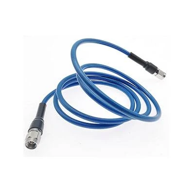
This image shows an RF cable assembly used for connecting RF components. Cable type, connector interface, impedance, and frequency range all affect transmission performance.
RF cables are not only physical connections between two components. They influence how much of the transmitted signal actually reaches the destination.
In an RF system, the cable carries controlled-frequency signals between modules, antennas, filters, test equipment, or other RF components. Any change in impedance, shielding, or cable construction can affect the transmission path.
A practical RF cable selection normally involves several basic factors:
- Impedance matching
- Operating frequency
- Signal attenuation
- Shielding effectiveness
- Mechanical installation requirements
Most RF systems use 50Ω cables, especially in communication equipment, test systems, and antenna applications. Some broadcast and video systems use 75Ω cables. Mixing these standards can create signal reflection and measurement problems.
The cable construction also matters.
A coaxial RF cable usually contains four main parts:
| Cable Structure | Function | Selection Consideration |
| Center conductor | Carries RF signal | Material and diameter affect loss |
| Dielectric | Maintains conductor spacing | Influences impedance |
| Shield layer | Reduces interference | Important in noisy environments |
| Outer jacket | Protects cable structure | Affects durability and flexibility |
Two cables may both be listed as coaxial cable and both have 50Ω impedance, but they may behave differently in actual use.
A flexible cable is easier to route inside compact equipment. A low loss cable may be preferred for longer antenna connections. A semi-rigid cable may be selected when mechanical stability and repeatable RF performance are more important than flexibility.
The correct choice depends on where the cable will be installed.
Where Are RF Cables Used Across Different Industries?
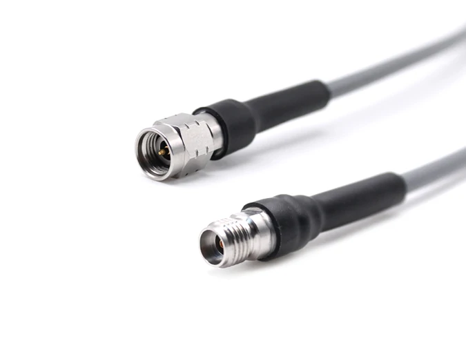
An IPEX to SMA antenna cable provides a compact RF connection solution for wireless devices where space and signal stability are important considerations.
Base stations and communication devices often require cables with controlled attenuation because signal loss accumulates over distance.
In smaller wireless products, the priorities change.
A GPS module inside a compact device may need a thin antenna cable with a small bend radius. A Wi-Fi module may require a miniature coaxial cable that can fit into a limited enclosure. A cable used outdoors may need protection against moisture, vibration, or temperature variation.
The same RF cable specification cannot be applied to every application.
| Application | Common RF Cable Requirement | Main Concern |
| Wireless communication | Stable transmission | Impedance and loss |
| GPS / Wi-Fi antenna | Compact and flexible | Cable size and routing |
| RF test equipment | Repeatable measurement | VSWR and insertion loss |
| Industrial electronics | Noise resistance | Shielding performance |
A frequent mistake in procurement is selecting a replacement cable only because the connector interface matches.
For example, an SMA cable assembly may physically connect to equipment, but the cable behind the connector determines whether the assembly performs correctly. A cable designed for short internal wiring should not automatically replace a low loss cable used for antenna transmission.
Why Should RF Cable Selection Start Before Connector Selection?
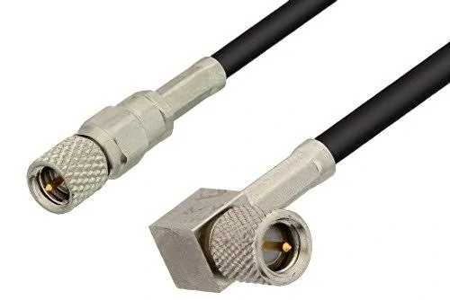
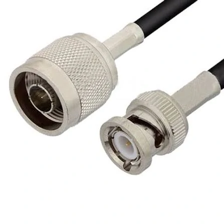
This RF cable assembly combines N Type and BNC interfaces for signal connection between different RF devices while maintaining 50 ohm impedance compatibility.
Many RF purchasing discussions begin with the connector:
“We need SMA.”
However, SMA only describes the interface standard. It does not define the complete cable assembly.
The same SMA connector family may be used with different cable types, including RG316, RG142, RG58, and low loss coaxial cables. These cables differ in diameter, attenuation, flexibility, and termination method.
Before selecting the connector, engineers usually need to define the cable requirement.
A more complete RF cable specification should include:
| Parameter | Example |
| Impedance | 50Ω |
| Frequency Range | DC–6 GHz |
| Cable Type | RG316 / RG142 / Low Loss Coax |
| Length | 500 mm |
| Connector Interface | SMA / BNC / N Type |
| Termination | Crimp / Solder |
| Test Requirement | Continuity / VSWR / Insertion Loss |
This approach avoids a common production problem: receiving a cable assembly that fits mechanically but does not meet RF requirements.
A continuity test can confirm that the electrical path is connected.
It cannot confirm that the RF path is suitable.
For higher frequency applications, additional verification such as VSWR, return loss, or insertion loss testing may be required before production release.
How Do You Select the Correct RF Cable Specifications?
A BNC RF cable assembly is commonly used in laboratory testing, communication equipment, and electronic measurement systems requiring reliable connections.
RF cable selection usually becomes difficult when the first quotation request arrives with incomplete information.
A customer may provide a connector model, cable length, and quantity, but leave out the parameters that actually determine whether the assembly will work.
For example:
- SMA male to SMA male
- 1 meter length
- 50 pieces
This describes the interface.
It does not describe the RF performance.
Before selecting a cable, engineers normally need to confirm several points:
- Operating frequency
- Required impedance
- Allowable signal loss
- Installation space
- Cable bending conditions
- Connector termination method
A cable assembly used inside a communication device has different priorities from one used for RF measurement.
The first one may require flexibility because the cable needs to fit around a PCB or housing.
The second one may prioritize phase stability, repeatability, and lower loss.
The cable specification should follow the application, not the other way around.
Does 50 Ohm Cable Always Mean the Same RF Performance?
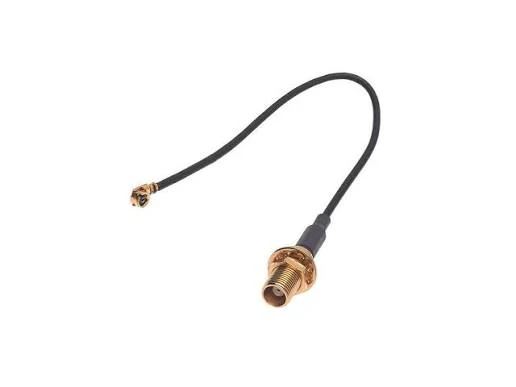
This RF cable assembly combines SMA and MMCX connectors, offering a flexible connection solution for compact RF devices and communication systems.
50Ω is one of the most common specifications in RF systems, but it does not describe the complete cable behavior.
Two cables can both be marked as 50Ω coaxial cable and still have very different characteristics.
The differences may come from:
- Conductor material
- Dielectric structure
- Shield design
- Cable diameter
- Manufacturing process
In RF applications, impedance matching is only one part of the selection process.
A system designed for 50Ω transmission expects the cable, connector, and equipment port to work together. If one part does not match, reflected energy can increase.
The result may appear as:
- Higher VSWR
- Reduced transmitted power
- Unstable measurement results
A simple continuity test will not detect this problem.
The connection may be electrically closed while the RF performance is already outside the expected range.
| Parameter | Why It Matters During Selection |
| Impedance | Keeps the RF path matched |
| Frequency Range | Determines whether the cable is suitable for the signal band |
| Attenuation | Controls signal loss over cable length |
| Shielding | Reduces external interference |
| Cable Diameter | Affects installation and connector matching |
For purchasing teams, the safest approach is to include impedance together with frequency and cable type in the specification.
“50Ω cable” is only the starting point.
How Should Operating Frequency Affect RF Cable Selection?
Frequency is where many cable substitutions fail.
A cable may work correctly in a low-frequency prototype and show unexpected loss after moving to a higher-frequency production environment.
The reason is simple: RF losses increase as frequency rises.
The cable that looks acceptable on a product drawing may become the limiting component in the actual RF path.
When evaluating frequency requirements, engineers usually consider:
- Current operating frequency
- Maximum possible frequency
- Required performance margin
A practical example:
A cable used around 2.4 GHz Wi-Fi does not automatically become suitable for an 18 GHz test system just because both applications use SMA connectors.
The connector interface is the same.
The RF requirement is not.
| Application | Cable Selection Focus |
| Wi-Fi antenna connection | Size, flexibility, acceptable loss |
| GPS module | Miniature structure and stable connection |
| RF test equipment | Repeatability and low loss |
| Microwave equipment | Frequency margin and assembly consistency |
Another issue appears during product upgrades.
A design may initially operate at 3 GHz but later require 6 GHz support. If the original cable was selected without enough margin, the assembly may need to be redesigned.
Replacing the cable after production starts is usually more expensive than selecting the correct specification earlier.
Why Can Cable Diameter and Flexibility Affect Production Results?
Electrical performance is only one side of RF cable selection.
Production engineers often discover mechanical problems after receiving samples.
A cable that performs well in testing may not be suitable for assembly if:
- The bend radius is too large
- The cable is difficult to route
- The connector receives excessive pulling force
- The cable length changes after installation
This happens frequently with compact electronic products.
The designer has limited internal space. The cable needs to pass around batteries, shields, brackets, or PCB components. A cable with excellent electrical performance may not physically fit.
Flexible coaxial cables solve many installation problems, but flexibility usually involves trade-offs.
A thinner cable normally provides easier routing.
A larger cable structure may provide:
- Lower attenuation
- Better shielding
- Higher mechanical strength
| Cable Type | Suitable Situation | Consideration |
| Flexible coaxial cable | Internal device wiring | Easy routing, higher loss possible |
| Low loss coaxial cable | Longer RF transmission path | Larger size |
| Semi-rigid cable | Stable laboratory connections | Limited flexibility |
The selection depends on what the system values more.
A short internal Wi-Fi antenna cable and a 2-meter RF measurement cable should not be evaluated using the same standard.
How Does RF Cable Construction Influence Transmission Quality?
A coaxial cable looks simple from the outside.
Inside, the relationship between each layer determines how the cable behaves.
The connector termination may no longer be correct.
Possible results include:
- Weak crimp connection
- Poor cable retention
- Signal instability after bending
This is why cable compatibility should always include the connector termination method.
How Can Engineers Estimate RF Cable Loss Before Production?
Cable loss is often underestimated during early design.
A short cable may have little impact in a prototype.
A lower-cost cable may look attractive initially, but additional loss may affect the final system performance and require compensation elsewhere.
In RF projects, the cable is rarely just a passive accessory.
It is part of the signal path.
Why Can the Same RF Connector Perform Differently in Different Cable Assemblies?
During RF cable sourcing, it is common to focus on the connector first.
A customer may ask for:
“SMA to SMA cable.”
From a purchasing perspective, this seems clear.
From an RF engineering perspective, several questions are still missing.
What cable is behind the SMA connector?
Is it RG316, RG142, RG58, or another coaxial cable?
What frequency will the assembly actually carry?
Will the cable be installed in a fixed position or bent repeatedly during operation?
These details affect the final result.
The connector only defines the connection interface. The complete RF path includes the cable structure, dielectric material, shielding, termination process, and installation condition.
This is why two RF cable assemblies with the same connector combination can have different electrical performance.
A cable used inside a wireless device may prioritize flexibility and size.
A cable used for RF measurement may prioritize stability and repeatability.
They may look similar from the outside, but the design target is different.
Which RF Connector Should Match Your Cable Application?
The connector selection usually follows the equipment requirement.
Common RF connector options include SMA, BNC, N Type, TNC, and 3.5 mm connectors.
Each connector family has typical application areas.
| Connector | Common Application | Selection Focus |
| SMA | RF modules, wireless devices, laboratory equipment | Cable compatibility and frequency |
| BNC | Test instruments and general RF connections | Quick mating and durability |
| N Type | Antenna systems and outdoor equipment | Low loss and environmental resistance |
| TNC | Outdoor communication systems | Mechanical reliability |
| 3.5 mm | High frequency measurement | Precision assembly |
A connector should not be selected only because it fits the port.
Mechanical compatibility is only the first check.
For RF applications, engineers also care about:
- Impedance
- Frequency range
- VSWR
- Insertion loss
- Mating cycles
A connector that works well in a low-frequency system may not be the correct choice for a higher-frequency measurement application.
What Problems Usually Appear During RF Cable Assembly Production?
Many RF cable issues are discovered after the first batch, not during quotation.
The reason is that production introduces variables that are not visible in a drawing.
For example, a cable assembly may pass the initial sample test.
After mass production, problems may appear because:
- Cable stripping length changed
- Crimp height was inconsistent
- The connector pin position shifted
- The cable was bent closer than expected
- The assembly operator used the wrong processing method
These issues are especially important for customized RF cable assemblies.
A small difference in termination can affect RF performance.
This is why experienced suppliers usually control several production points:
| Production Check | Purpose |
| Incoming material check | Confirm cable and connector specification |
| Processing inspection | Control stripping and termination |
| Electrical test | Verify connection condition |
| RF performance test | Check VSWR or insertion loss |
| Final inspection | Confirm appearance and labeling |
A cable assembly that passes continuity testing has confirmed the circuit path.
It has not necessarily confirmed the RF performance.
How Are Antenna Cables Selected for Wireless Products?
Antenna cable applications create a different type of challenge.
The cable often needs to fit inside a limited space while maintaining acceptable signal transmission.
This situation is common in:
- GPS devices
- WiFi equipment
- IoT products
- Wireless modules
The cable route may change several times during product development.
A prototype enclosure may allow a gentle cable curve.
The final housing may force a tighter bend.
That mechanical change can influence the cable selection.
For antenna cable applications, engineers normally review:
- Frequency band
- Cable diameter
- Bend radius
- Connector size
- Cable length
- Expected loss
A smaller coaxial cable is easier to install.
However, reducing cable size may also affect attenuation and shielding.
The final decision is usually a compromise between available space and RF requirements.
FAQ
I already have the SMA connector model. Do I still need to confirm the cable type?
Yes. The connector model only tells part of the assembly requirement. The same SMA interface can be used with different coaxial cables, and the final performance may change depending on cable diameter, attenuation, frequency range, and termination method. Before production, the cable behind the connector should be confirmed together with the application.
Is a 50Ω RF cable enough information for supplier quotation?
Usually not.
50Ω only defines the impedance requirement. A supplier still needs to know the working frequency, cable structure, length, connector type, and expected test requirements. Two 50Ω coaxial cables can have different loss, flexibility, and shielding characteristics.
If I already know the SMA connector, do I still need to confirm the cable?
Yes, because SMA only tells the interface.
The cable behind it can still be different. RG316, RG142, and low loss coaxial cables may all use SMA connectors, but their diameter, loss, flexibility, and frequency capability are not the same.
For a quotation, it is better to provide the connector together with the cable type and working frequency.
Is a 50Ω RF cable specification enough for ordering?
Not in most cases.
50Ω only defines the impedance.
The supplier still needs to know where the cable will be used, how long it should be, what frequency it will carry, and which connectors are required.
Two 50Ω cables can have different attenuation and mechanical characteristics.
